In the fifteenth week we were tasked to create a network with at least two PCBs and program them to communicate. There are a lot of samples on the FABacademy site to choose from.
Here is a list of tasks as I see them for the fourteenth week.
I decided to make an asynchronous serial circuit. I used the "hello.bus.45.bridge" board and two "hello.bus.45.node" boards. The program files found in the Network and Communications lecture outline are designed to flash an LED twice on the board called for in the program and flash once on the other two boards. "hello.bus.45.make" contains the files needed to create the boards. "hello.bus.45.c" contains the program to run the circuit.
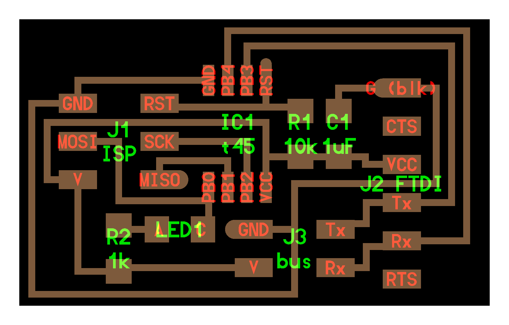
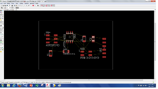
Here is an image of the bridge board.
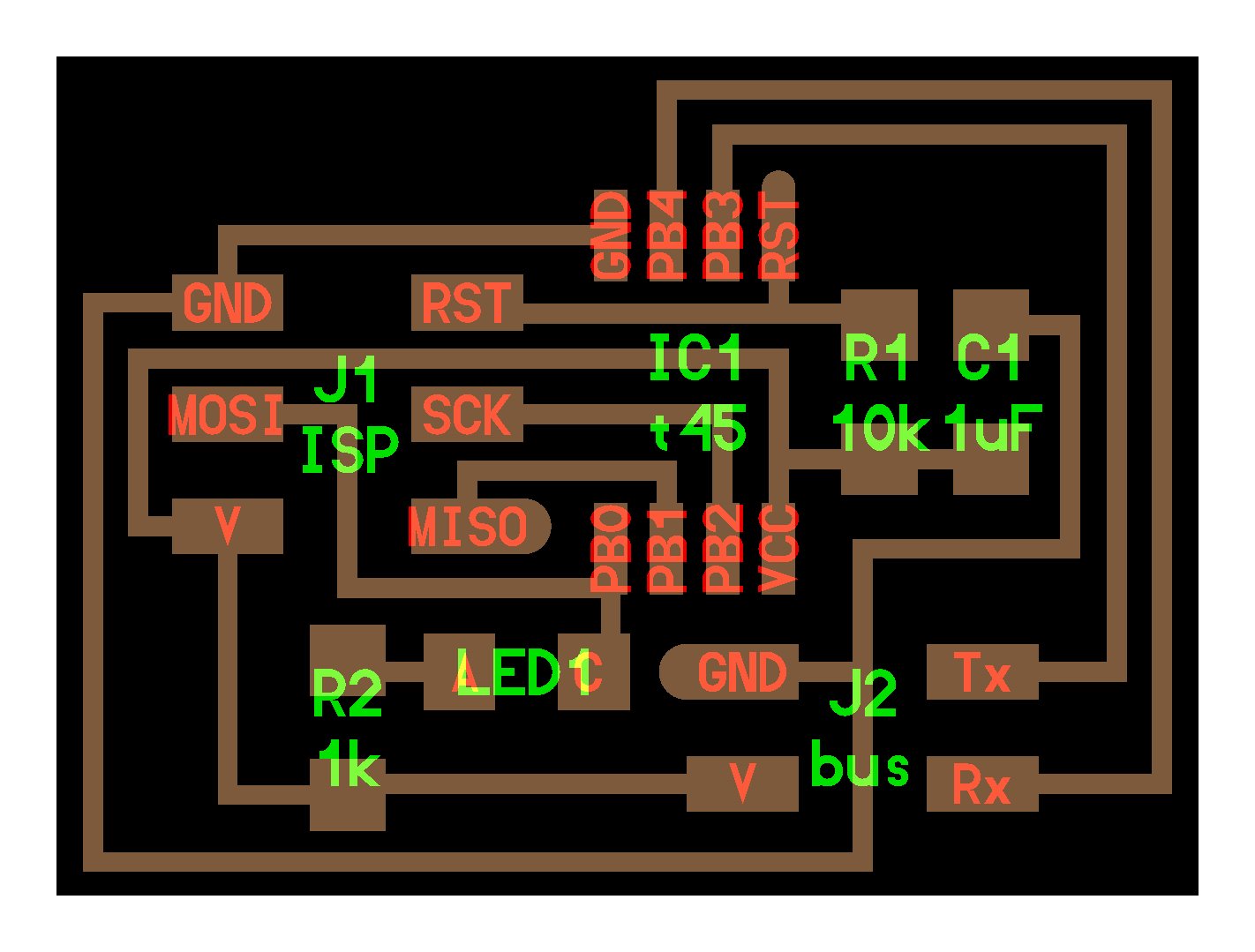
Here is an image of the node board.
I used Eagle Cad to design the two boards. It is getting easier to program the boards as I get more practice. All I need to do in Eagle is load the FAB electronic components library and place the proper components where needed.
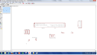
Here is an image in Eagle of all the components needed to build the bridge board but they are not yet connected to each other.
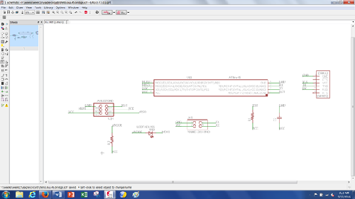
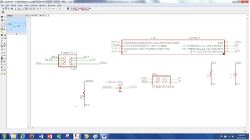
Here is an image of the bridge board schematic with associations needed for wiring.
Once the schematic is designed and the wiring labels are assigned component placement and trace creation can begin. Eagle will populate the board for you but it will place the components outside of the board design area. The programmer needs to place the components in position to allow for correct wire routing. Yellow lines appear with components showing where the wires need to be run. The yellow lines are created by the labeling process in the schematic.
Here is an image showing the bridge board components placed properly to begin the wire routing process.
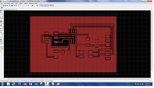
Here is the same bridge board after wire routing. Note that all copper material will not be removed in the machining process. It will be used as a ground/heat sink.
Here is an image of the node board schematic.
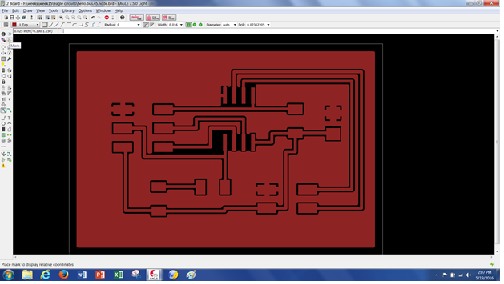
Here is an image of the "node" board after wire routing.
From Eagle Cad I created the Gerber files needed to machine the boards. I made one bridge board and two node boards.
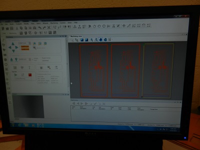
I used a 0.016" (1/64") tool to machine the traces.Here is an image of the cam software to create the CNC code.
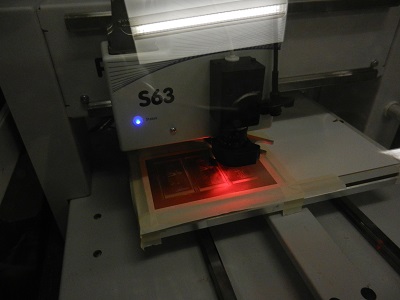
Here is an image of the boards being machined.
After machining it is time to populate the boards (solder the components on). I need to populate one bridge board and two node boards.
Here are the machined board and the components to make a bridge circuit board,
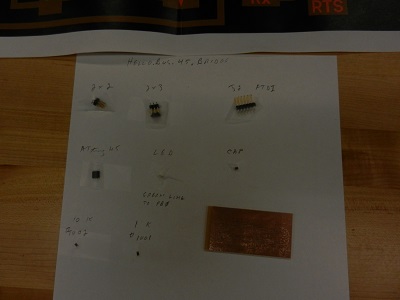
And here are the machined board and the components to make one node circuit.

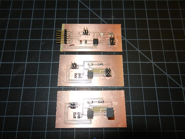
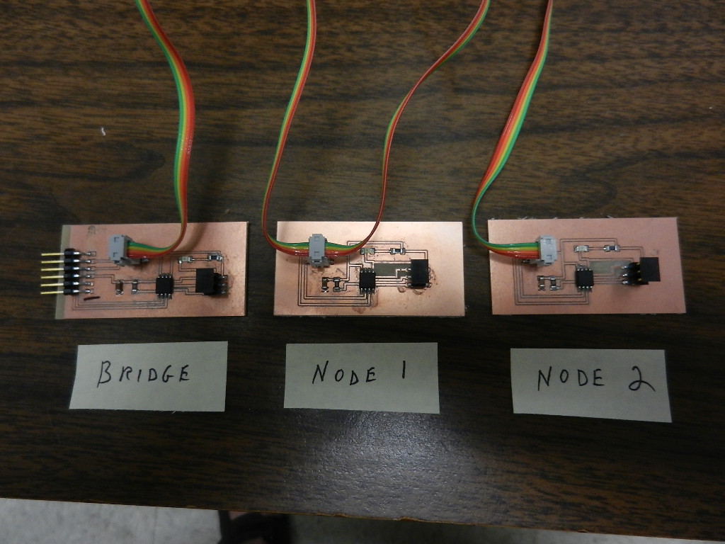
This image shows the finished bridge board and two node boards.
The next thing to do is program the boards.
The command "python term.py/dev/tty/usb0 9600" Sets up a "device" called "ATTiny" through "usb zero" to run at a baud rate of 9600.
A FTDI cable is used to connect to the board to transfer this command. The FTDI is a board we made earlier that is used to program other boards.
The serial cables were made with 40-strand wire. Care had to be taken to orient the pins correctly.
You can see in the next picture how the connectors are all aligned in the same direction and the boards are oriented in the same direction.
The red wires are all on the same pins on each board.
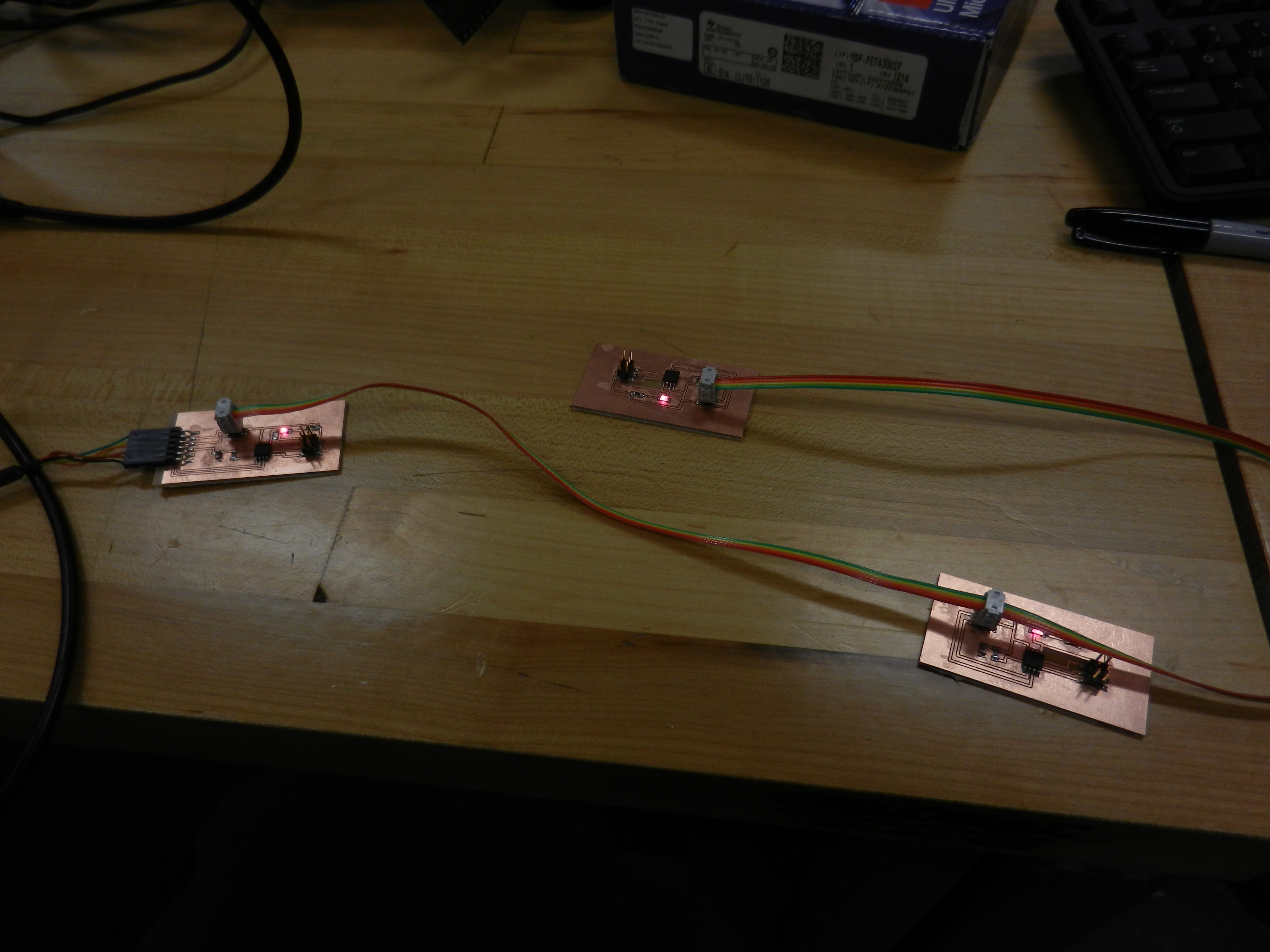
Here is an image showing the lights flashing.
There were minimal problems encountered with this assignment. My Eagle Cad and soldering techniques are improving. One problem I had was trouble shooting problems with the boards after they were soldered. We have a group of people working together when making our boards. Some had problems with the boards and some did not. We discovered that the ATtiny45 chips we had on some boards were defective. When replaced with new chips (either individually or as a total remake of the board) the problem disappeared. We never discovered what the problem was with the ATTiny 44 chips but more than 10 of them were found to be defective.
The last problem encountered was my insufficient knowledge of "C" and "python". I assume that those will improve during the next few weeks as we finish our projects.
The following files should allow someone to reproduce the results I had.