The eleventh week built on our exposure to PCBs. In this week we are to pick one of the sample boards given that utilize some kind of input.
Here is a list of tasks as I see them for the eleventh week. (Not necessarily in this order)
My main project for the course is to make a vacuum forming machine. I decided for this exercise to make a board that senses temperature.
I chose the sample board "hello-temp-45" to make.
Here is the sample board from the FABacademy website.
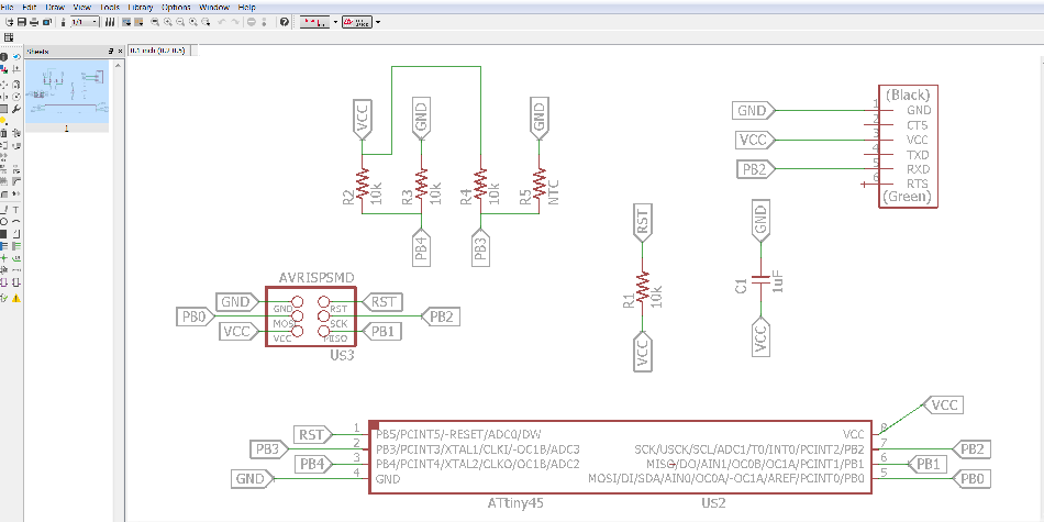
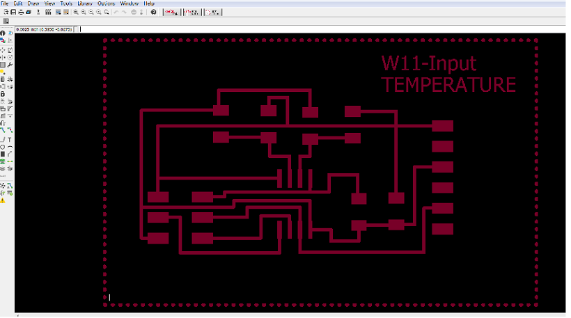
I used Eagle CAD software to design my circuit, w11-input.sch. Looking at the original board in the FAB Academy archive I knew what components needed to be used and where to connect them. I first had to activate the fab library of components. In eagle you add your comnponents to the schematic and drag them to approximate positions. Once all components are placed connections must be made. I used a labeling method to run the wires.
Here is a picture of my schematic for this circuit. The screenshot for my traces is shown below.
Using the traces I created Gerber files and used them to machine\ two boards to populate.
I always like to make a spare in case there are problems.
Here is what the traces from FABacademy look like.
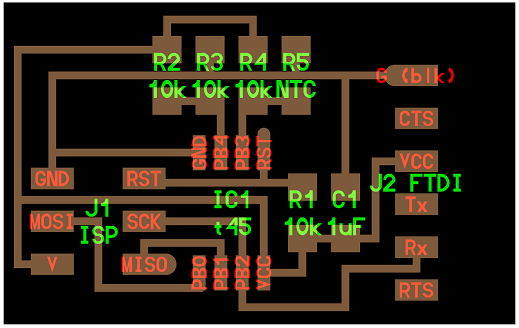
Here is what my traces look like in Eagle software.
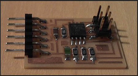
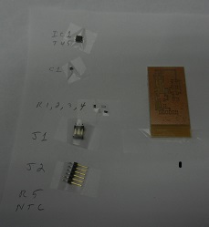
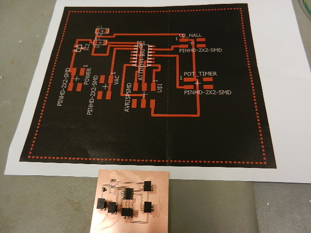
Here is one of my machined boards on a sheet of paper with all the components needed to make the circuit.
I am starting to enjoy the challenge of soldering the small surface mount parts. As long as I remain relaxed I have little trouble attaching the components.
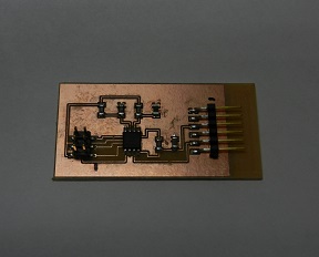
Here is a picture of my board with all the components applied. I was told to be careful not to put too much heat on the thermister.
Programmimng in "C" is not one of my strong points. I have Neil's samp[le "C" program (hello-temp-45-c) downloaded.
I did not have to modify the code for this lab because I used the same pinout as the sample file.
Chris Rohal an electronics instructor at LCCC helped me to program the board. I need to get better at the "C" language.
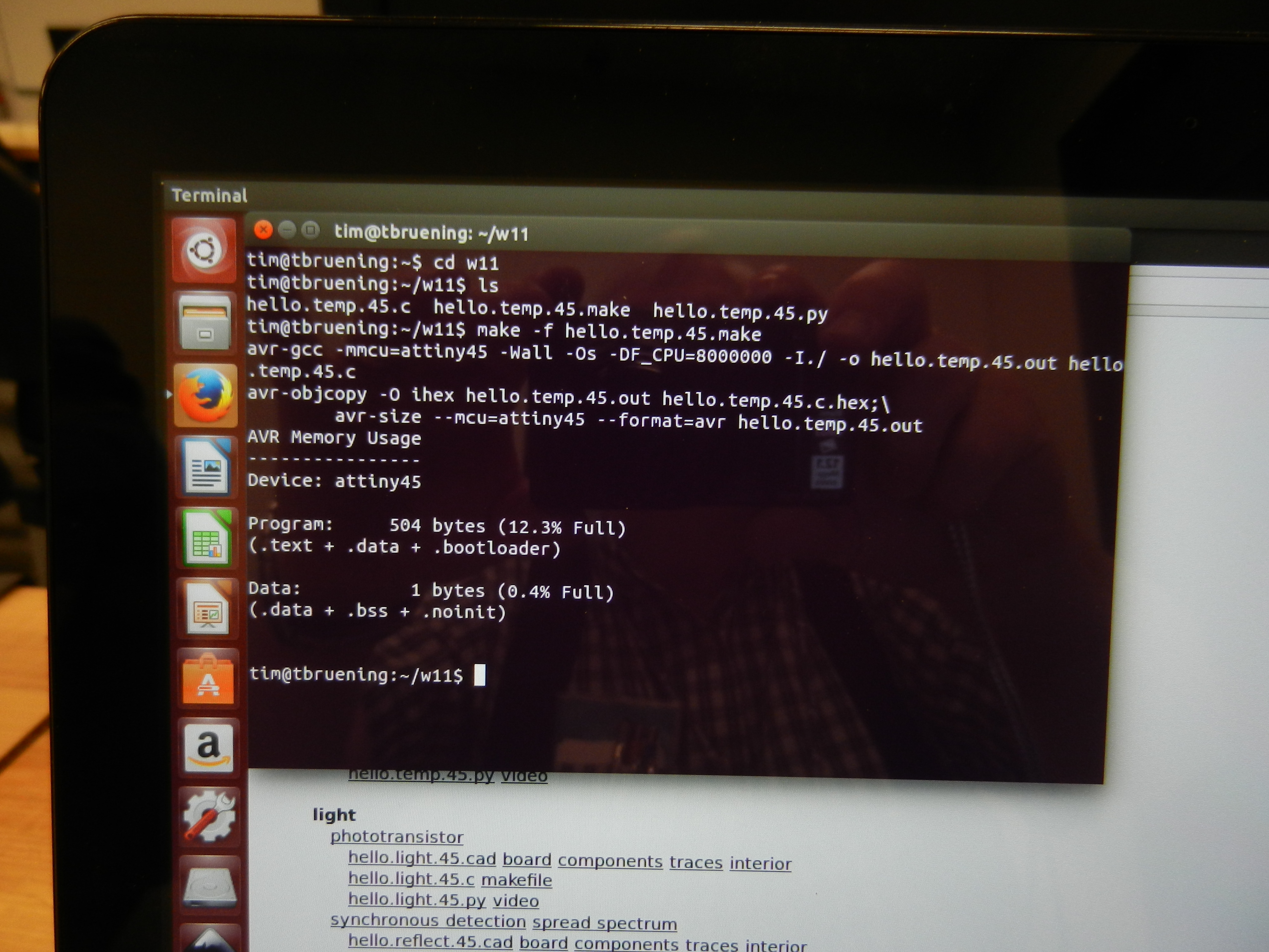
To compile the python code. (make -f hello.temp.45.make)
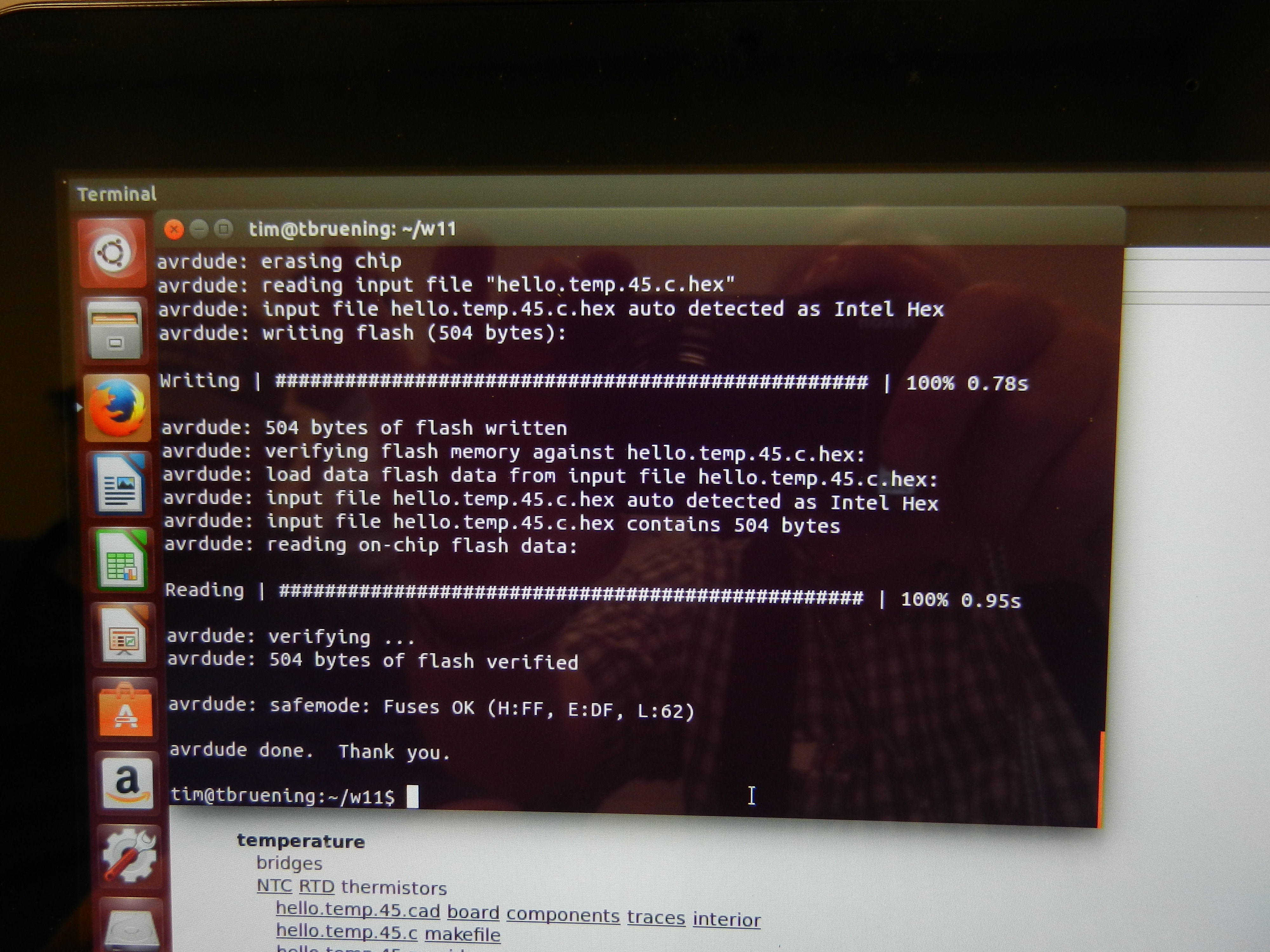
To flash the code to the microcontroller. (make -f hello.temp.45.make p;rogram-usbtiny)
The last thing is to run the python code. (sudo python hello.temp.45.py/dev/ttyusb0)
Here are some photos showing some of the steps I used to program the board.
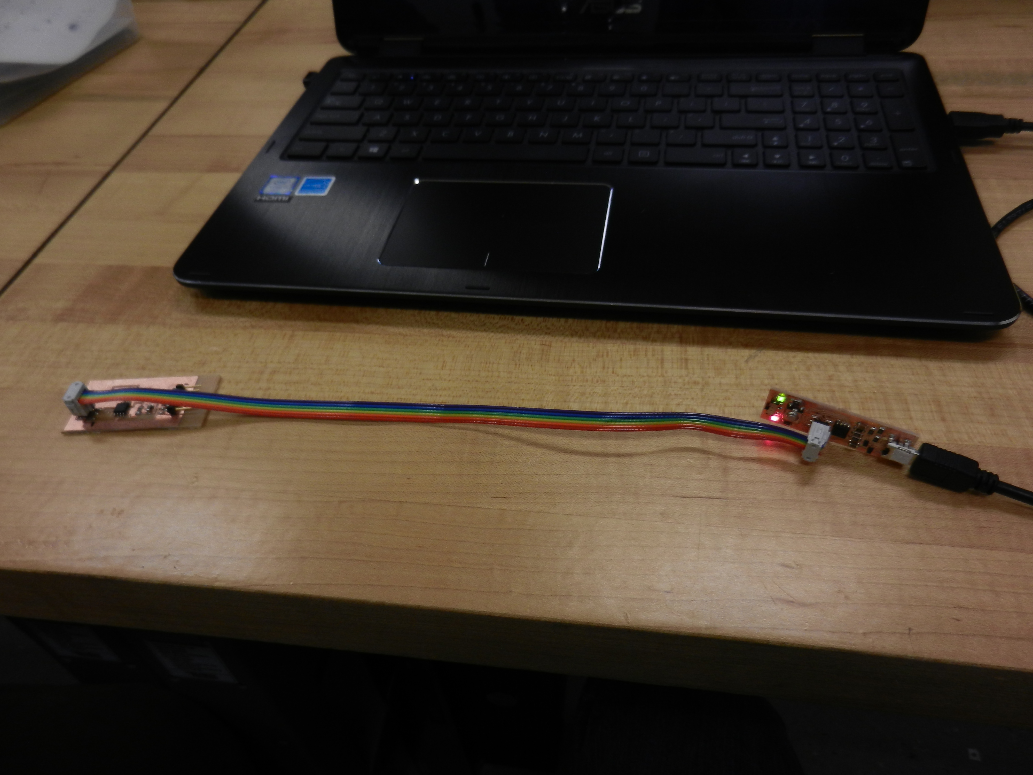
Here are some shots showing the changing temperature inputs coming from the board.
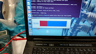
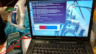
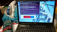
When testing the board we did not think it was working. A cold object was placed on the thermister and the temperature icon was not moving.
Chris and I were trying to find out what was wrong. It appeared that the board was transmitting. After awhile we put the entire board into the freezer and it started working.
You can see from the previous photos that the temperature inputs were changing
I needed to build two boards for this project. After discussions with my mentor and other electronics people I decided to make a smaller, separate board for the hall effect sensor.
It will be easier to place and keep the main board away from the heat.
The main board will house the ATTiny44 micro controller and all the 2 x 2 connectors needed to integrate all components.
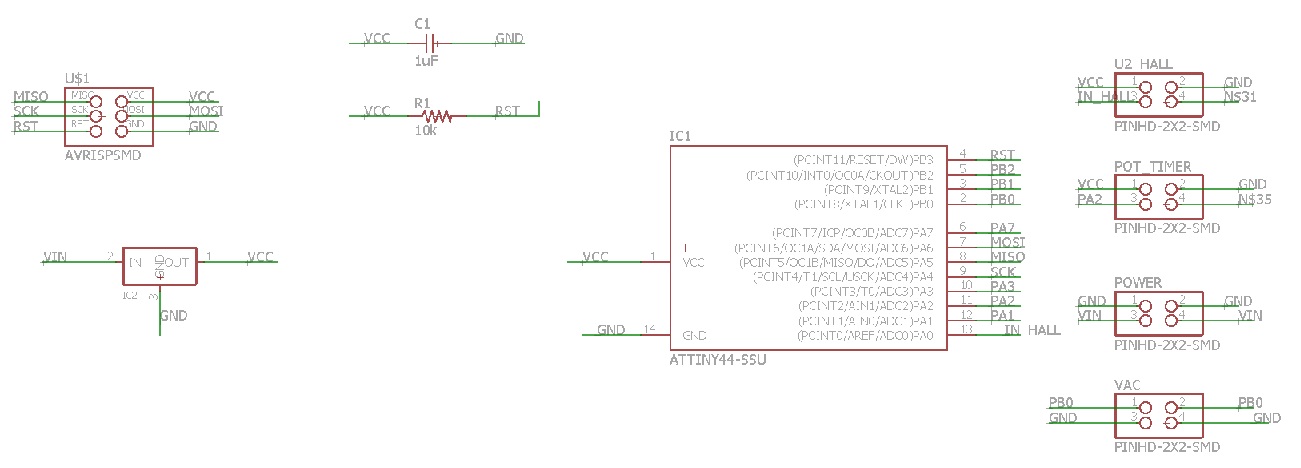
Here is a screenshot of the schematic for the ATTiny44 board.
Here is a screenshot of the traces for the final ATTiny44 board.
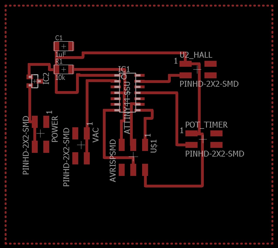
This is a picture of the completed ATTiny44 board and the traces used to make it.
Here is the schematic for the hall effect sensor.
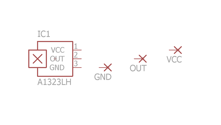
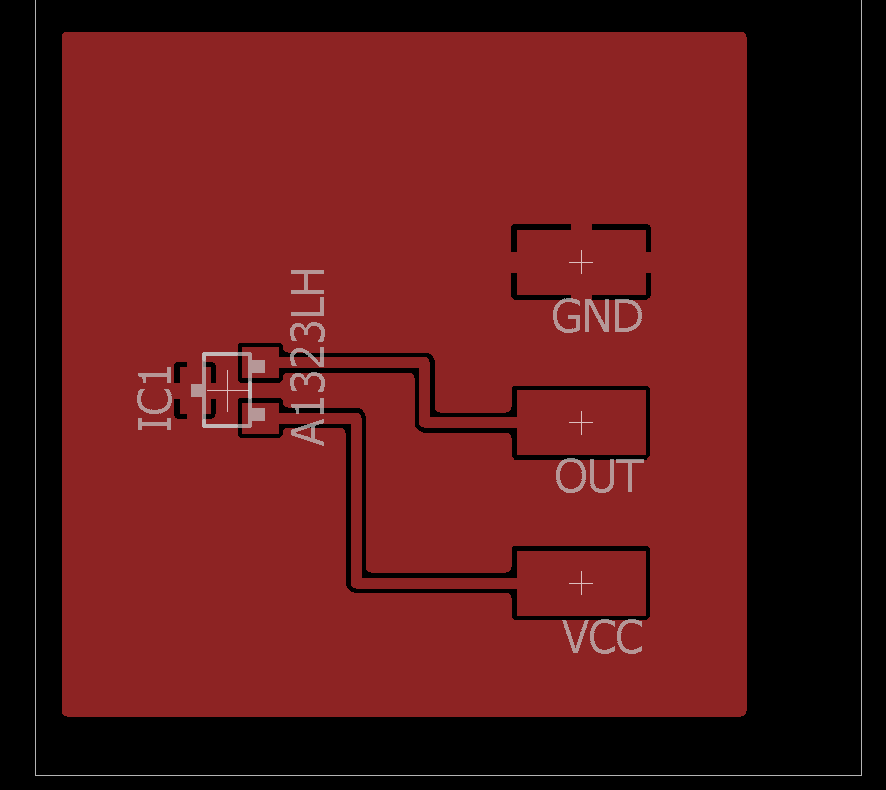
Here are the board traces for the hall effect sensor.
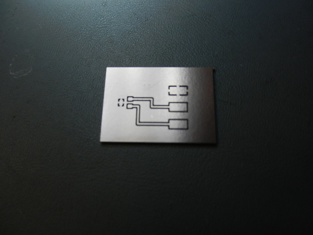
Here is the hall effect sensor before populating.
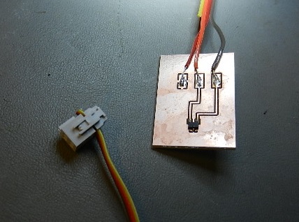
Here is the finished hall effect sensor board.
For my final project I decided to use Arduino programming. To me it seems simpler than the "C" programming we used in earlier programs.
The Arduino code is easier for me to understand. I am able to walk through each line of code and explain what is happening.
Here is my final project program. The explanations in RED are not part of the program They are added for explanation only.
void
setup()
{
setup only runs
once on startup
// put your setup code
here, to run once:
pinMode(10,OUTPUT);
define pin #10 as
an output
}
int
sensorValue =0; // variable for hall read on A0
set hall effect input to zero
int
TimeValue=0; //
potentiometer input
set pot.
input to zero
int
timescale=0; // pot variable
set pot. variable to zero
void
loop()
{
loop forever
constantly scan code
// put main code here, to
run repeatedly:
sensorValue
= analogRead(0); //
read voltage on A0
hall
effect
input from A0
TimeValue
=
analogRead(2); //
read voltage on A2
pot.
input
from A2
timescale = TimeValue * 10;
controls variable
delay from pot.
if(
sensorValue < 200)
true if correct
magnetic pole is present
{
delay(10000);
wait 10,000
milliseconds (10 seconds)
delay(10000);
“
delay(10000);
“
delay(10000);
“
delay(10000);
“
delay(10000);
“
delay(10000);
“
delay(4000);
wait 4,000
milliseconds (4 seconds)
delay (timescale);
wait value from pot.
digitalWrite(10,HIGH);
set pin #10 to high
(turn on vacuum pump)
}
while(sensorValue
< 200)
keep pin #10 value
high as long as sensorValue < 200
{
(as long as sensor
detects magnetic field)
sensorValue
= analogRead(0);
sets sensorValue to
500 when burner is moved
away from hall
effect sensor
}
digitalWrite(10,LOW);
set pin #10 to low
(turns off vacuum pump)
}
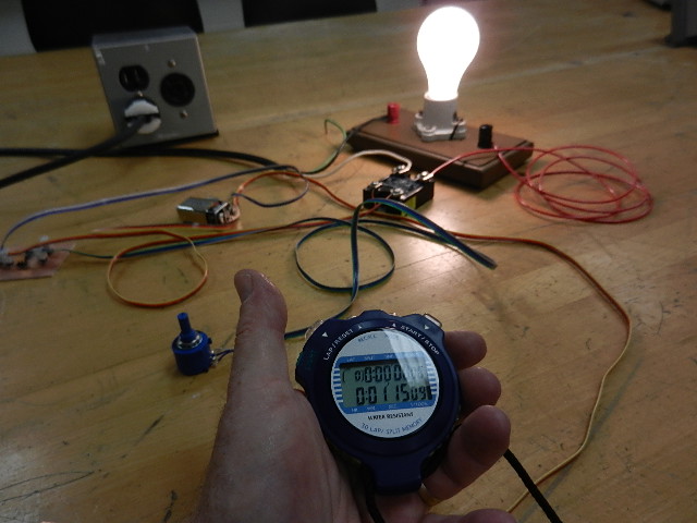
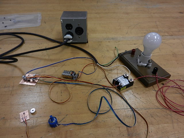
Now that the boards are programmed they have to be tested. I wired them up using a 9 volt battery and 110 volt jumper wires.
The light bulb is filling in for the vacuum pump.
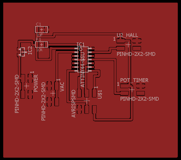
Looking at the ATTiny44 board schematic and board images you will see four 2x2 connectors. These are used to connect all the components together.
Power 2 x 2 --- This connector has a 9 volt battery connected to it. 2 pins connect to ground (GND) and 2 pins are connected in series to the voltage regulator.
The voltage regulator (on the ATTiny44 board) feeds 5 volts
(VCC) to
the 1uF capacitor, 10k ohm resistor, pin 1 on the Hall 2 x 2, pin 1 on
the Pot 2 x 2 and the AVRISPSMD.
Hall 2 x 2 ---- This connector has 1 pin to VCC, 1 pin to GND, 1 pin to
Pin 13 on the ATTiny44 and one pin unused.
Pot Timer 2 x 2 ---- 1 pin to VCC, 1 pin to GND, 1 pin to Pin 11 on the ATTiny44 and 1 pin unused.
VAC 2 x 2 ---- 2 pins connected to Pin 2 on the ATTiny44 (PB0 output to terminal on DC side of relay) and 2 pins (GND) to other terminal on DC side of relay.
---- 2 wires to GND and 2 wires to Pin 2 are twisted together.
The AC side of the relay has one wire coming from the hot 110 volt wire and one wire going to one side of the outlet in the blue box.
The other wire (neutral) from AC 110 goes directly to the remaining terminal of the outlet.
The vacuum pump is plugged into the outlet. It will only come after the programmed delays.
The ATTiny44 board is programmed with a 75 second delay (determined through testing).
Here you can see the test setup.
Here you can see the test setup after the hall effect sensor has been manually triggered.
You can see the stopwatch recorded 1 minute and 15 seconds. 75 seconds total.