At the beginning of this class I decided to build a green house to begin sprouting seeds for a garden. I began work on this project during week one of this course. My project has since taken on a couple of different forms and ideas, but the main idea has never changed.
During WEEK 1 of Fab Academy I came up with a preliminary design to build this green house. What I had planned was a bit over reaching for my capabilities at the time and over the course of the class my project was scaled down to be able to complete the electronics portion of Fab Academy..
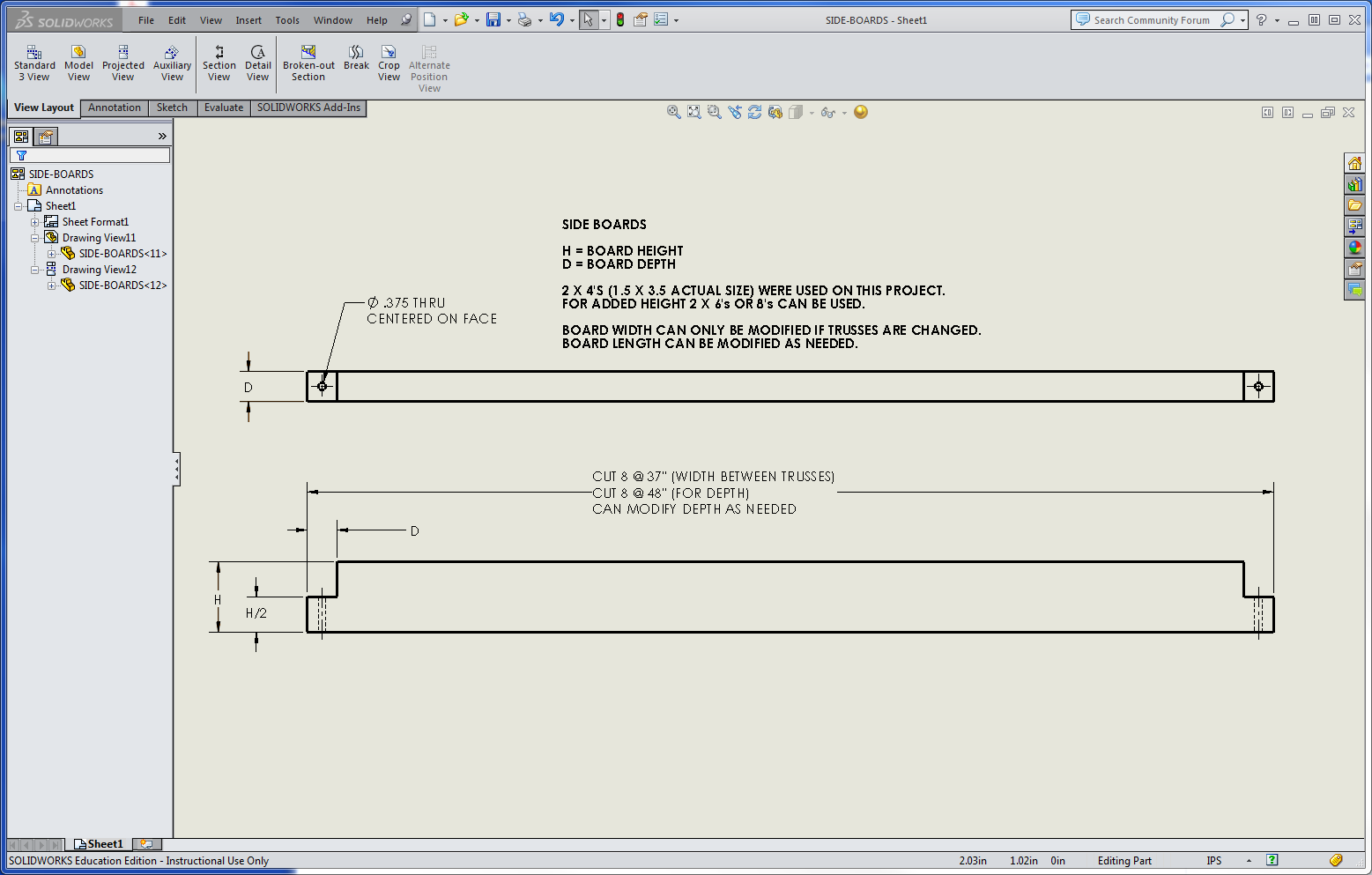
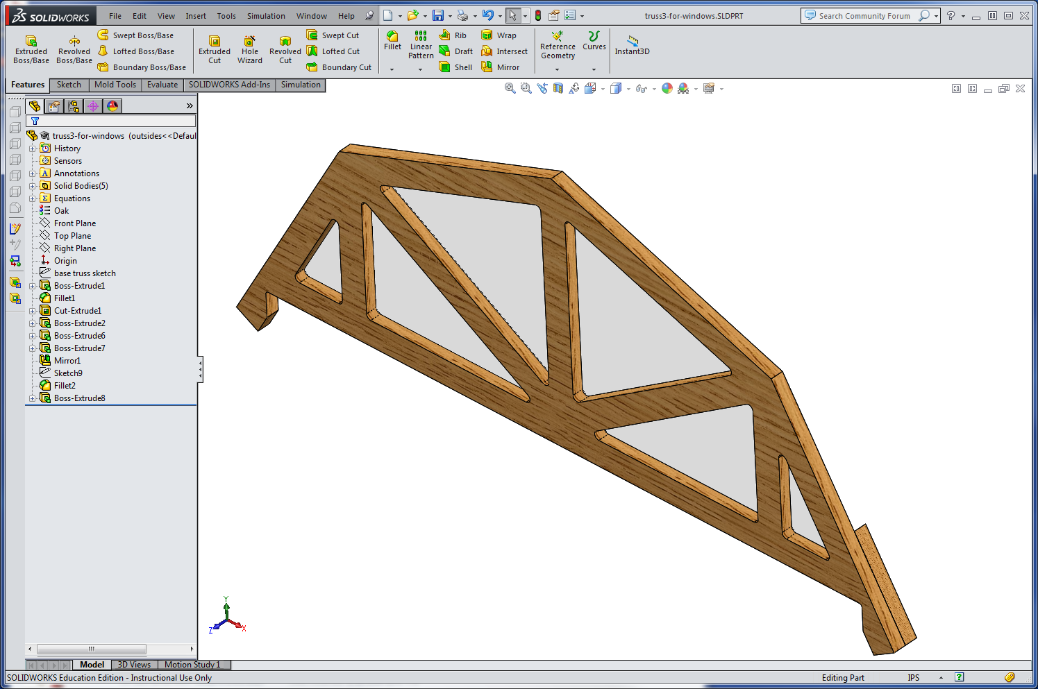
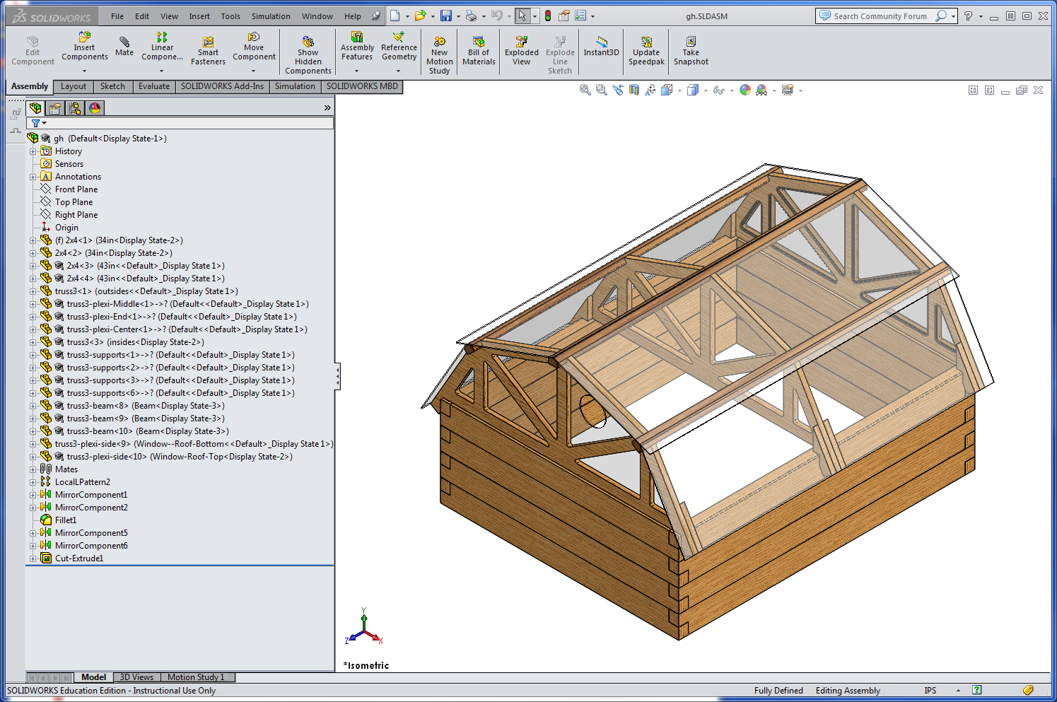
During WEEK 2 I was able to use computer aided design to lay out a preliminary project. By the end of the eighteen weeks the project remained the same but the desgn took on a bit of a change. New ideas came about with new processes learned.
Week number four and six and eight, and eleven is where I learned of my weakness in electronics, electronics production, and programming; everything during these weeks was new so this is is where my project had to be scaled back. Thank goodness there were boards and programs that I was able to use. I decided to drop the solar panel, battery, and heat source and just focus on temperature and a cooling fan.
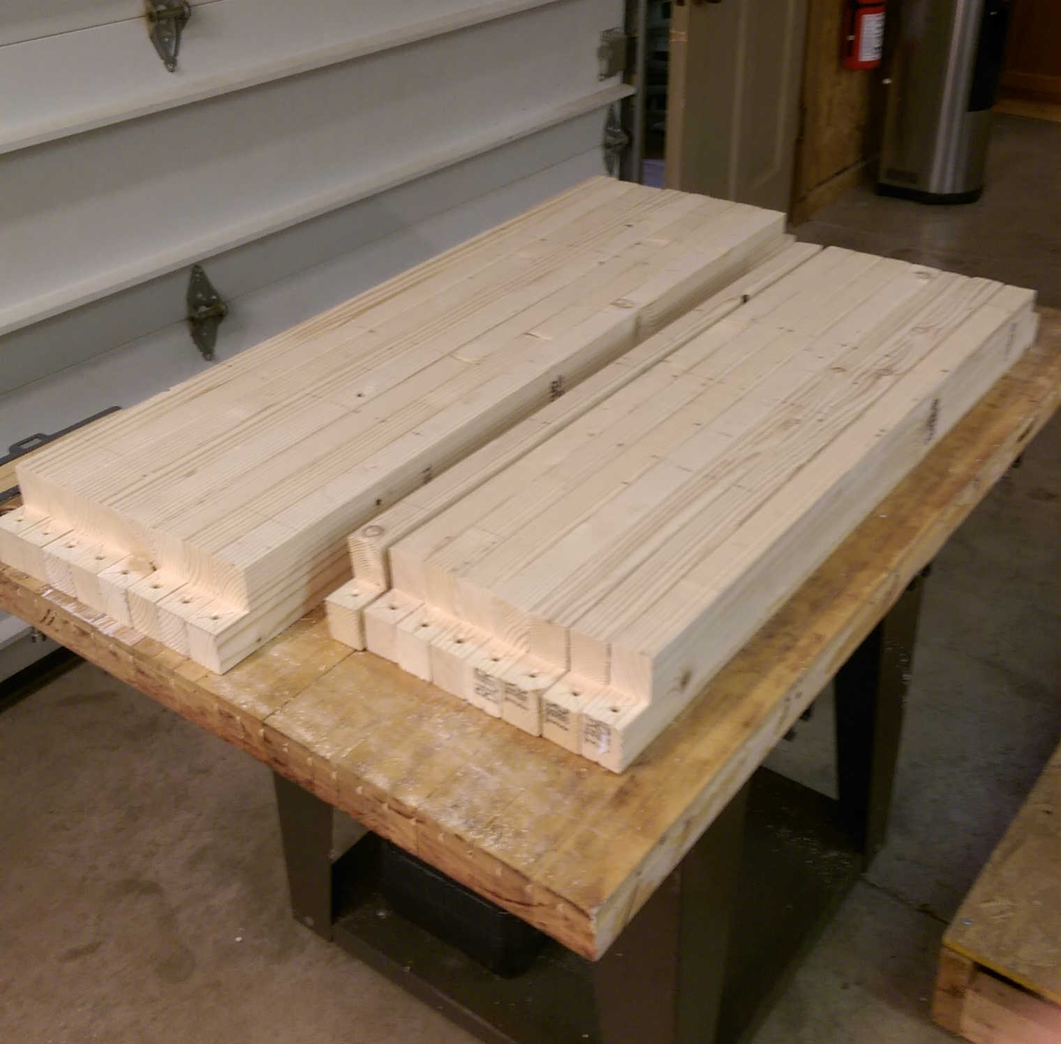
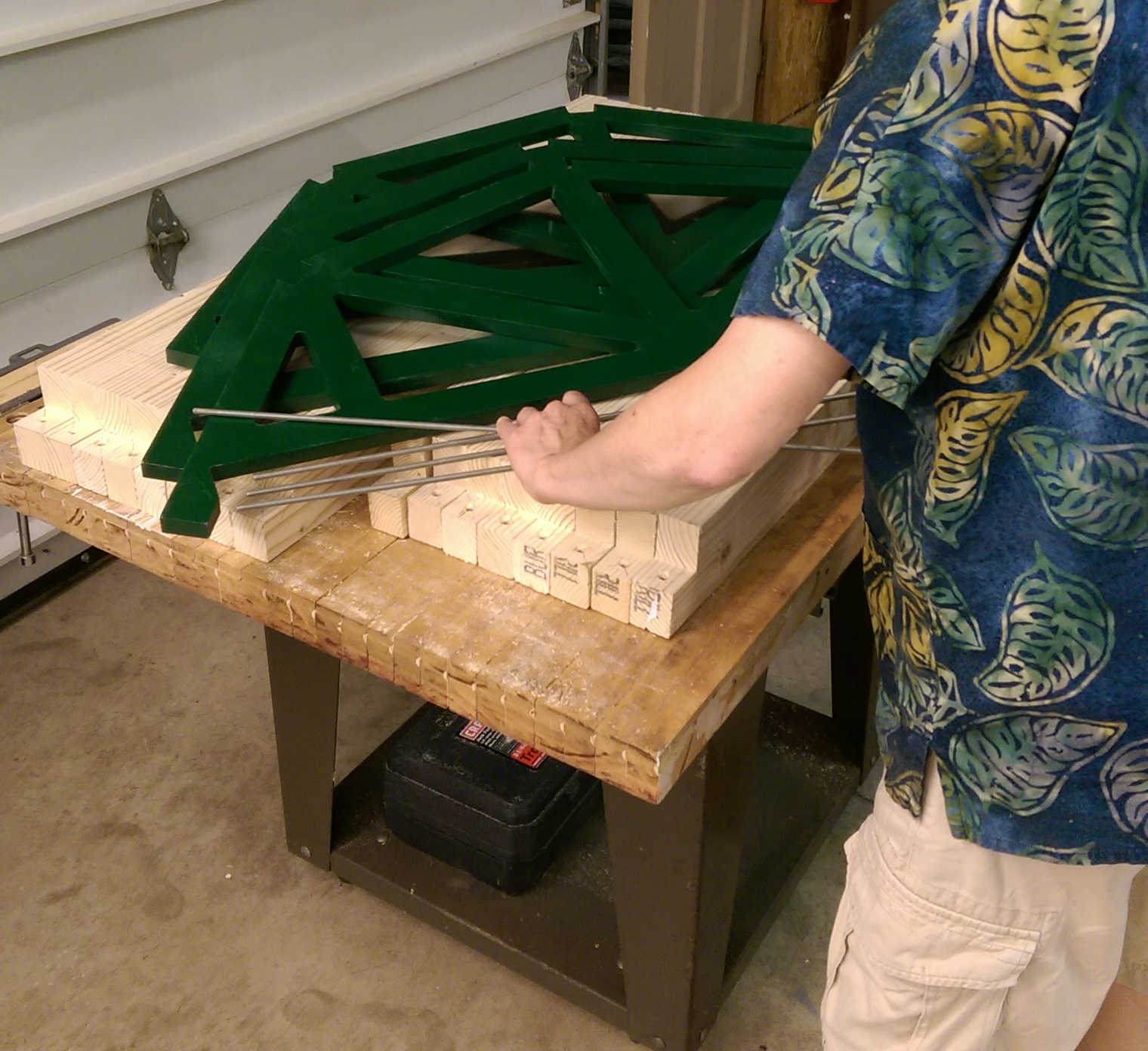
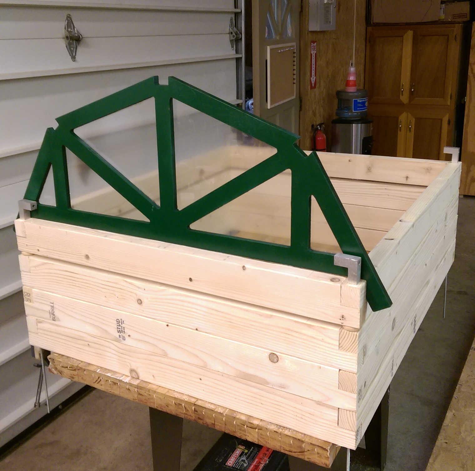
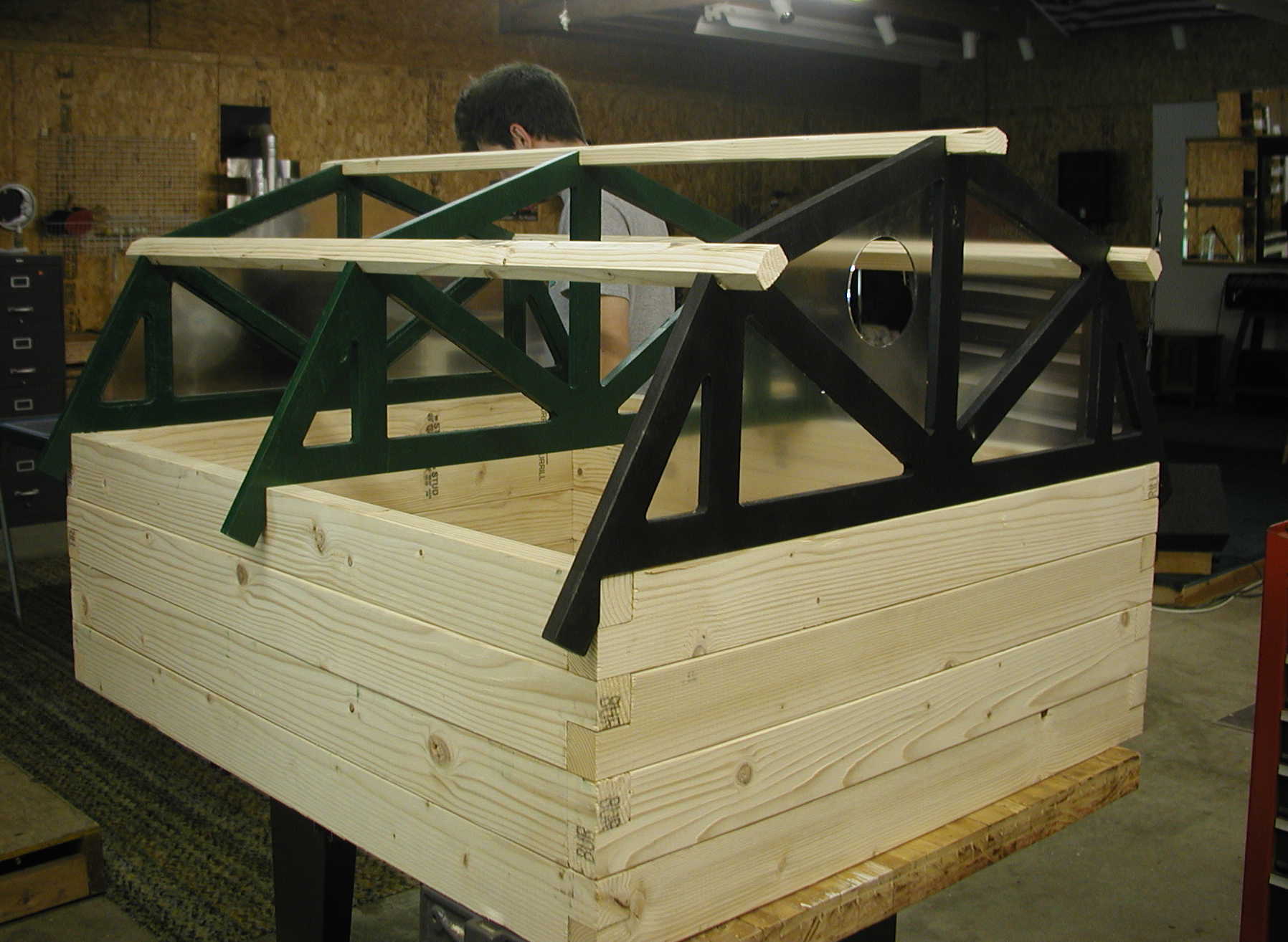
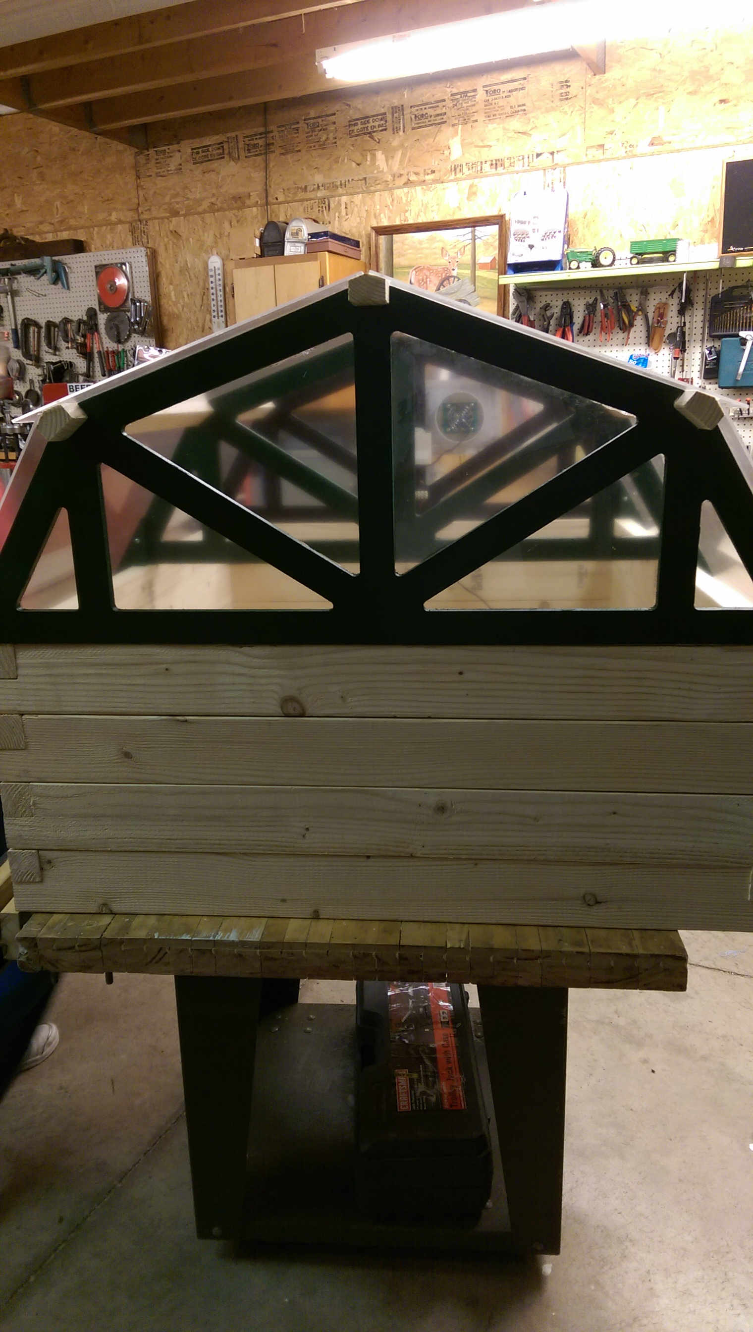
WEEK 7 was the actual start of the production of the green house. This is when the trusses and walls were cut using Computer Controlled Machining and the windows were cut on the laser using the skills from week three, Computer Controlled Cutting.
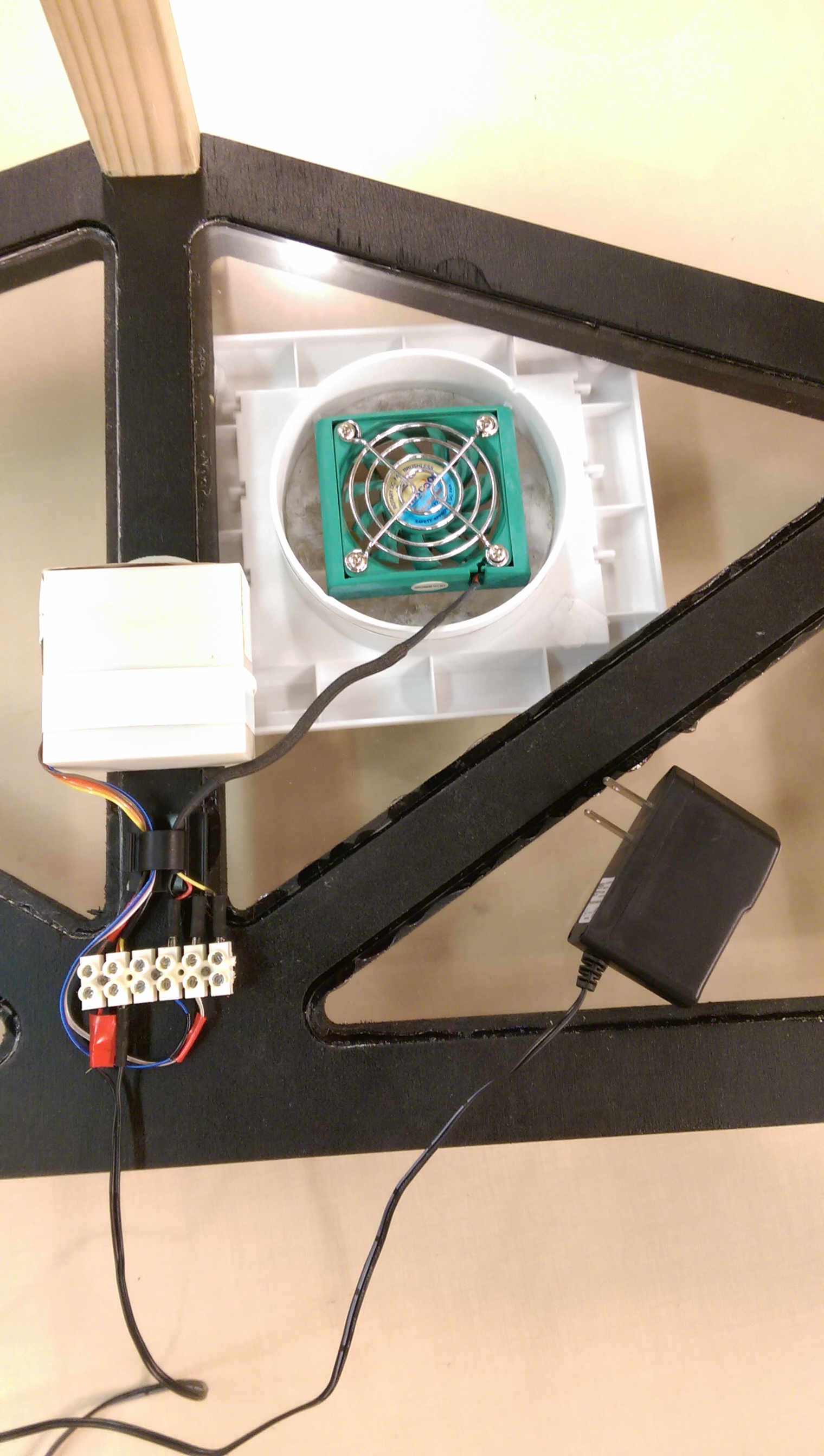
By the time I got to WEEK 13 I felt confident enough to combine the input board, on temperature, with the output board for the DC motor. I was able to combine the Brush DC motor circuit with the circuit from input week on temperature. Also, both programs were combined and with a little help from a friend the program was successful. Even though Week 13 shows a siren/strobe from a fire alarm, this circuit is able to start any 12VDC device attached. This is the board and circuit used for my green house. When the temperature gets too hot the fan will start and move the hot air from the green house.
I also designed and 3d printed (from Week 5) a holder for the board and cable management in order to keep things neat and orderly inside this project. The board is powered by a 12VDC power source from a 120 VAC outlet.
WEEK 17 discusses the final project that integrates the range of units covered and answers various questions about this project.

3D Printed Box to hold cables and Board


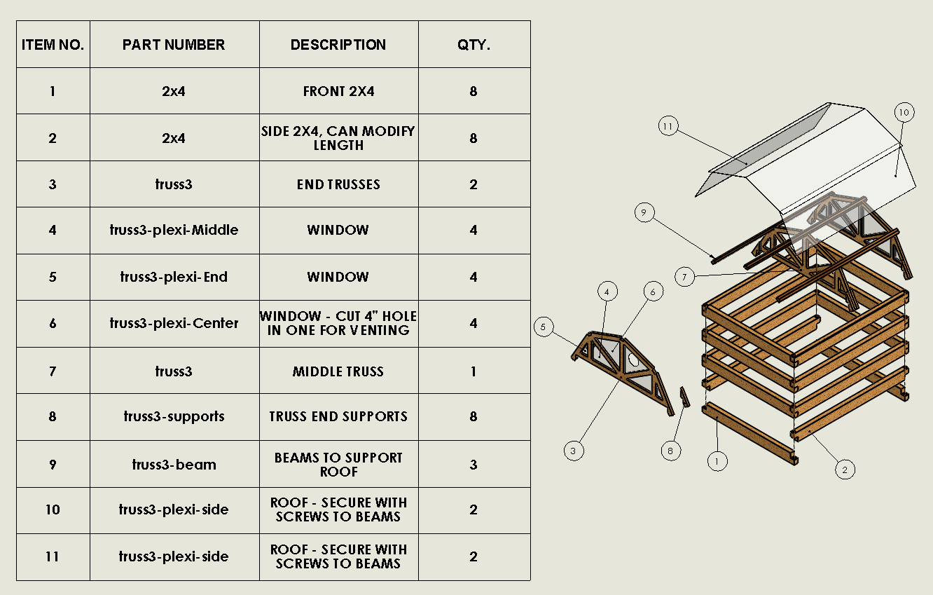
Solidworks Files
Download all solidworks files. There are multiple configurations on some part files.
STL files
Board, Schematic, and Program
DXF files