

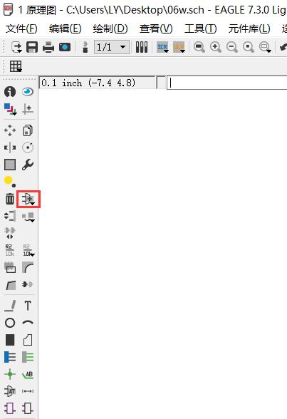
Eagle is a software for making a schematic data and circuit board design.
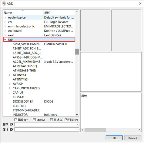
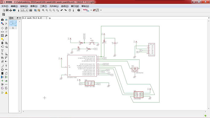
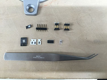
To find all the necessary electronic components from the Fab database and Connect them according to instructions.
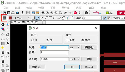
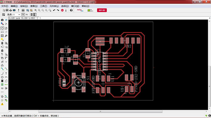
Switch to circuit board mode, move the electronic components and connect them. I chance the units to mm to make my work more smoothly. This is the first time I have designed a board, so I spend so much time on this step.
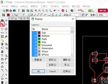
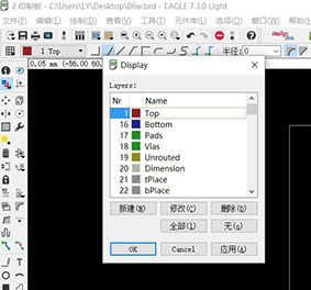
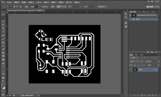
After I finished the work, I turn on the layer management, leaving only the TOP layer.
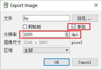
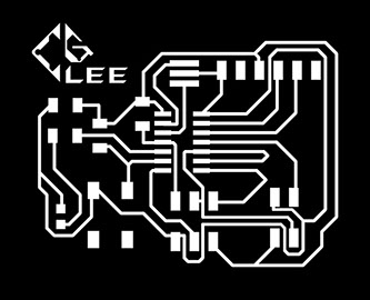
Then choose to export image, set the DPI as 1000, and Choose the monochrome.
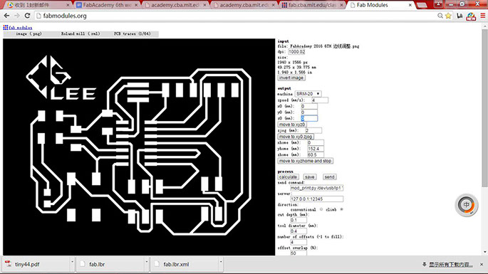
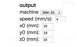
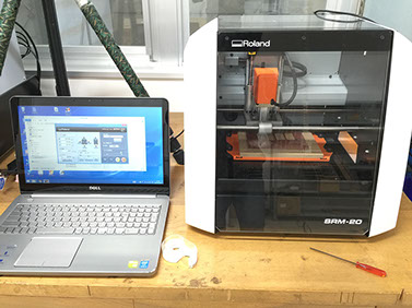
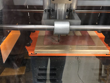
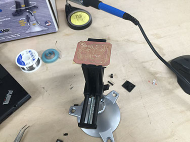
At first, fixed the board on the wood board with the 3M double side glue, and then set the XYZ axis, at last I fixed the drill.
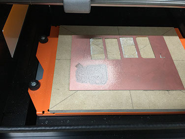
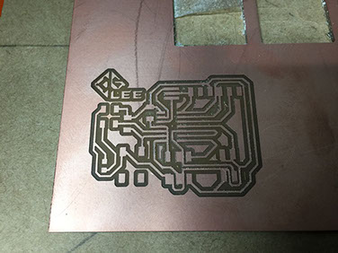
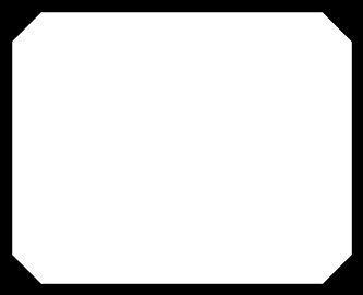
First I cut out the traces using the 0.4mm drill, and then cut the outline with the 0.8mm drill.
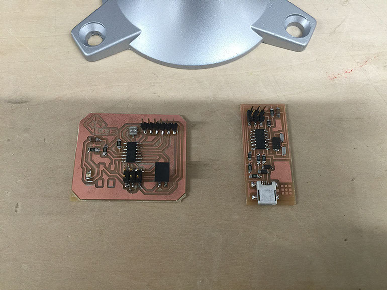
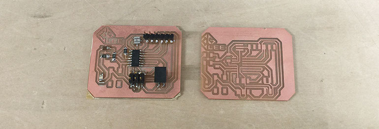
We use 3M's double-sided tape to fixed the board when cutting. But when I cut the periphery, the board was carried away from the milling machine by the drill. I can only stop cutting, according to the approximate location to reset the origin, try to cut again. Unfortunately, I failed. The second time, I use the hand to press the board to ensure that the board is firmly fixed, Then I cut a new one.