Week 13: Output Devices
For Simple Absorption Meter
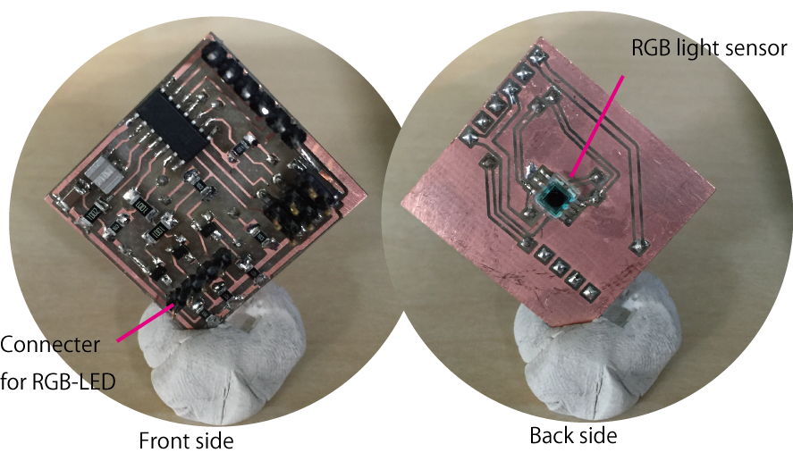
The concept is absorption measurement devise ("Called absorbance meter") for quick check of research. The input device is RGB sensor, and output device will be white LED. Currently I got S9032 of Hamamatsu
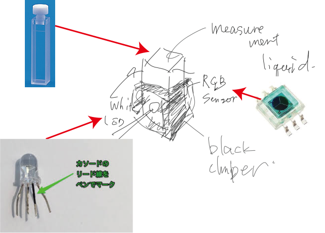
Output Device
The full color LED I used is LED-TR-501-A from Linkman. The data sheet is here. It is partially in Japanese.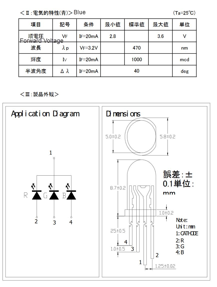
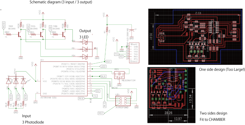
sch file
brd file
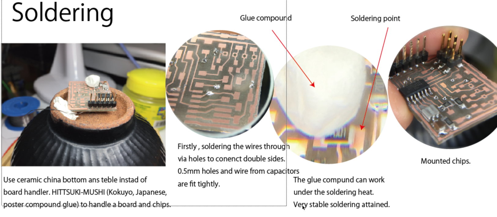
Since the cell holder's size is 30mm width, I would like to limit the board size less than 30mm. However, single-sided designing made side larger. Therefore, I tried to fabricate a double sided board.Fabricate double sided circuit board
This is my first trial to fabricate double-sided circuit board. I add s9032-02 in new library (oki.lbr) from data sheet.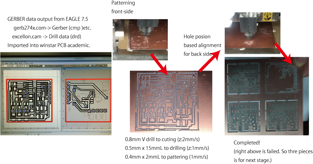
Unfortunately, I just finish fabricating the sensor / light source board. I will try pogram it later.
Program Development
The C code for gcc-avr was used for the device. The program code is as follows:
#include#include #include #define output(directions,pin) (directions |= pin) // set port direction for output #define input(direction,pin) (direction &= (~pin)) #define set(port,pin) (port |= pin) // set port pin #define clear(port,pin) (port &= (~pin)) // clear port pin #define pin_test(pins,pin) (pins & pin) // test for port pin #define bit_test(byte,bit) (byte & (1 << bit)) // test for bit set #define bit_delay_time 8.5 // bit delay for 115200 with overhead //#define bit_delay_time 102 // bit delay for 9600 with overhead #define bit_delay() _delay_us(bit_delay_time) // RS232 bit delay #define half_bit_delay() _delay_us(bit_delay_time/2) // RS232 half bit delay #define char_delay() _delay_ms(10) // char delay #define serial_port PORTA #define serial_direction DDRA #define serial_pins PINA #define serial_pin_in (1 << PA0) #define serial_pin_out (1 << PA1) //#define serial_pin_out (1 << PB2) #define ledR_port PORTA #define ledB_port PORTB #define ledG_port PORTA #define ledR_direction DDRA #define ledG_direction DDRA #define ledB_direction DDRB #define ledR_pin PA6 #define ledG_pin PA5 #define ledB_pin PB2 #define offBlue set(ledB_port, (1 << ledB_pin)); #define onBlue clear(ledB_port,(1 << ledB_pin)); #define offGreen set(ledG_port,(1 << ledG_pin)); #define onGreen clear(ledG_port,(1 << ledG_pin)); #define offRed set(ledR_port,(1 << ledR_pin)); #define onRed clear(ledR_port,(1 << ledR_pin)); #define pdR_port PORTA #define pdG_port PORTA #define pdB_port PORTA #define pdR_pin PA7 #define pdG_pin PA3 #define pdB_pin PA2 #define pdR_direction DDRA #define pdG_direction DDRA #define pdB_direction DDRA #define max_buffer 25 static int blueflag=0; void get_char(volatile unsigned char *pins, unsigned char pin, char *rxbyte) { // // read character into rxbyte on pins pin // assumes line driver (inverts bits) // *rxbyte = 0; while(pin_test(*pins,pin)) ; // // wait for start bit // // // delay to middle of first data bit // half_bit_delay(); bit_delay(); // // unrolled loop to read data bits // if pin_test(*pins,pin) *rxbyte |= (1 << 0); else *rxbyte |= (0 << 0); bit_delay(); if pin_test(*pins,pin) *rxbyte |= (1 << 1); else *rxbyte |= (0 << 1); bit_delay(); if pin_test(*pins,pin) *rxbyte |= (1 << 2); else *rxbyte |= (0 << 2); bit_delay(); if pin_test(*pins,pin) *rxbyte |= (1 << 3); else *rxbyte |= (0 << 3); bit_delay(); if pin_test(*pins,pin) *rxbyte |= (1 << 4); else *rxbyte |= (0 << 4); bit_delay(); if pin_test(*pins,pin) *rxbyte |= (1 << 5); else *rxbyte |= (0 << 5); bit_delay(); if pin_test(*pins,pin) *rxbyte |= (1 << 6); else *rxbyte |= (0 << 6); bit_delay(); if pin_test(*pins,pin) *rxbyte |= (1 << 7); else *rxbyte |= (0 << 7); // // wait for stop bit // bit_delay(); half_bit_delay(); } void put_char(volatile unsigned char *port, unsigned char pin, char txchar) { // // send character in txchar on port pin // assumes line driver (inverts bits) // // start bit // clear(*port,pin); bit_delay(); // // unrolled loop to write data bits // if bit_test(txchar,0) set(*port,pin); else clear(*port,pin); bit_delay(); if bit_test(txchar,1) set(*port,pin); else clear(*port,pin); bit_delay(); if bit_test(txchar,2) set(*port,pin); else clear(*port,pin); bit_delay(); if bit_test(txchar,3) set(*port,pin); else clear(*port,pin); bit_delay(); if bit_test(txchar,4) set(*port,pin); else clear(*port,pin); bit_delay(); if bit_test(txchar,5) set(*port,pin); else clear(*port,pin); bit_delay(); if bit_test(txchar,6) set(*port,pin); else clear(*port,pin); bit_delay(); if bit_test(txchar,7) set(*port,pin); else clear(*port,pin); bit_delay(); // // stop bit // set(*port,pin); bit_delay(); // // char delay // bit_delay(); } void put_string(volatile unsigned char *port, unsigned char pin, char *str) { // // print a null-terminated string // static int index; index = 0; do { put_char(port, pin, str[index]); ++index; } while (str[index] != 0); } // AD convert from channel adch // adch : 0-7 for ADC0~ADC7 // nos : Number of summention // div : division // Return Value = Sigma_n=1~nos (adinput(adch))/div uint16_t singleADC(uint8_t adch, uint16_t nos, uint16_t div) { uint16_t ret; uint16_t count; uint32_t sum; // clear(ADCSRA,(1 << ADEN)); //Turn of ADC ADMUX = 0b10000000; // Below operation DID NOT WORK!! Please use 1 line setting !! // clear (ADMUX,(1 << MUX5)|(1 << MUX4)|(1 << MUX3)| (1 << MUX2)|(1 << MUX1)|(1 << MUX0)); // set(ADMUX, (adch & (1 << MUX2)|(1 << MUX1)|(1 << MUX0))); // select adch by Lower three bits // if(adch&0b10000000) ADMUX = adch; ADMUX = ((1 << REFS1) | (0 << REFS0) | adch );// set Vcc as internal 1.1V set(MCUCR, (1 << PUD)); // set(ADCSRA, (1 << ADEN)); sum=0; for(count=0;count < nos;count++){ set(ADCSRA,(1 << ADIF));// Reset interrupt flag set(ADCSRA, (1 << ADSC));//Start ADC while (ADCSRA & (1 << ADSC));//Wait for ADC completion sum+=(uint32_t)ADC; } while (ADCSRA & (1 << ADIF)==0);//MAY BE NOT NEEDED (Wait for Interrrupt flag) ret=(uint16_t)(sum/div); return ret; } void put_number(volatile unsigned char *port, unsigned char pin, uint16_t number) { put_char(port, pin, ((uint32_t)number /10000)+48); // char_delay(); put_char(port, pin, ((number%10000) /1000)+48); // char_delay(); put_char(port, pin,((number%1000) /100)+48); // char_delay(); put_char(port, pin, ((number%100) /10)+48); // char_delay(); put_char(port, pin, (number%10)+48); } int main(void) { // // main // static char chr; static unsigned int value; static char buffer[max_buffer] = {0}; static int index; static int nsamples=1; static uint32_t accum; static uint16_t level_r; static uint16_t level_g; static uint16_t level_b; static int count; int loopcount=0; uint8_t bflag=0; uint8_t gflag=0; uint8_t rflag=0; // // set clock divider to /1 // CLKPR = (1 << CLKPCE); CLKPR = (0 << CLKPS3) | (0 << CLKPS2) | (0 << CLKPS1) | (0 << CLKPS0); // // initialize output pins // set(serial_port, serial_pin_out); output(serial_direction, serial_pin_out); // // initialize LED pins // set(ledR_port, (1 << ledR_pin)); output(ledR_direction, (1 << ledR_pin)); set(ledG_port, (1 << ledG_pin)); output(ledG_direction, (1 << ledG_pin)); set(ledB_port, (1 << ledB_pin)); output(ledB_direction, (1 << ledB_pin)); // Set clear(PORTA, (1 << pdR_pin)); input(pdR_direction,(1 << pdR_pin)); clear (PORTA, (1 << pdG_pin)); input(pdG_direction, (1 << pdG_pin)); clear (PORTA, (1 << pdB_pin)); input(pdB_direction, (1 << pdB_pin)); //set(MCUCR, (1 << PUD)); offGreen; offRed; offBlue; // // init A/D // //Caution DON DOT USE ADMUS |= xxxxx !! It made trouble!! ADMUX = (1 << REFS1) | (0 << REFS0) // Vcc is 1.1 V | (0 << MUX5) | (0 << MUX4) | (0 << MUX3) | (1 << MUX2) | (1 << MUX1) | (1 << MUX0); // MUX5=1, MUX4=0 で 0V入力; // ADMUX = 0b10000011; // test for temperature input ADCSRA = (1 << ADEN) // Enable ADC | (1 << ADPS2) | (1 << ADPS1) | (1 << ADPS0); // 分周を CK/128に set(DIDR0, (1 << ADC7D)|(1 << ADC3D)|(1 << ADC2D)); // May not be needed // // main loop // while (1) { get_char(&serial_pins, serial_pin_in, &chr); if (chr == 'b') if (bflag) {bflag=0;offBlue} else {bflag=1;onBlue}; if (chr == 'g') if (gflag) {gflag=0;offGreen} else {gflag=1;onGreen}; if (chr == 'r') if (rflag) {rflag=0;offRed} else {rflag=1;onRed;} // Read RGB level from level_g = singleADC(PA3,10,3); // 10 times sum / divided by 3 level_b = singleADC(PA2,10,5); level_r = singleADC(PA7,16,2); put_char(&serial_port, serial_pin_out,'R'); put_char(&serial_port, serial_pin_out,':'); put_number(&serial_port, serial_pin_out,level_r); char_delay(); put_char(&serial_port, serial_pin_out,','); put_char(&serial_port, serial_pin_out,'G'); put_char(&serial_port, serial_pin_out,':'); put_number(&serial_port, serial_pin_out,level_g); char_delay(); put_char(&serial_port, serial_pin_out,','); put_char(&serial_port, serial_pin_out,'B'); put_char(&serial_port, serial_pin_out,':'); put_number(&serial_port, serial_pin_out,level_b); char_delay(); put_char(&serial_port, serial_pin_out,13); char_delay(); put_char(&serial_port, serial_pin_out,10); char_delay(); } }
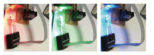
The LED bringhting in RGB separately with this program as below.
Though some document saied read ADCH and ADCL, but I did not seceeded reading-out with this symbol. I had to use ADC instead of them. In addtion, the signal from ADC7 gave the value around 200 even though the Vref of 1.1V was selected, I changed load resistance of PD's from 10kOhm to 100 kOhm. I guessed this resister is too high to get accuracy on the ADC, The remained problem is the ADC3 and ADC2 showed siilar value, and they ware not separated.
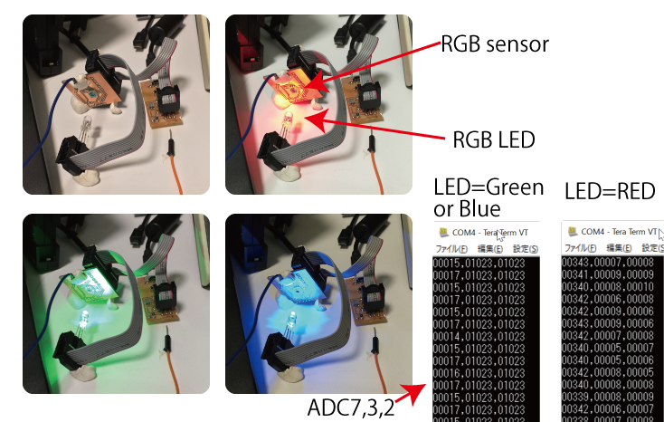
The above problem was hard to be fixed. Finally, I found the point to be fixed. When I used ADMUL|=xxx as partial bit operation on ADMUL, ADC7 works but ADC2 and ADC3 shows similar value. Since the signal value was not similar level, I changed sampling code as above. (R= *10/3, G=*10/2, B=*16/2). After the easy calibration, I slaso checked cross talk bitween wavelength. The each values from ADC were as follows:
- G_LED : r_ch=70 g=1420 b=202
- R: r=1360, g=20, b=10
- B: r=40 g=197 B=1360
- B_LED+G_LED: r=94 g=1650 B=1563
- B+R : r=1370 g=213 b=1353
- GR : r=1420 g=1489 b=206
- RGB : 1429 1699 1564