Riyas P.K-Fab Academy 2016
Networking and communications
The assignment for this week is to design and build a wired &/or wireless network connecting at least two nodes. I decided to make a small network based upon a serial asynchronous bus.The asynchronous serial interface is so called because the transmitted and received data are not synchronised over any extended period of time and therefore no special means of synchronising the clocks at the transmitter and receiver is necessary.
Designing the circuit
I decided to make the example board itself with some modification.
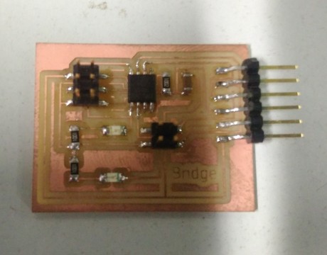
Bus bridge
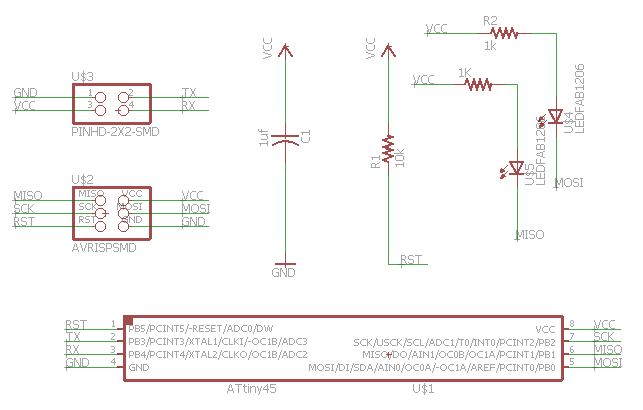
I used Eagle CAD to redraw the hello.bus.45.bridge design and added a second led.
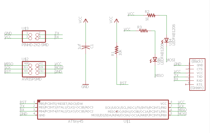
Schematic
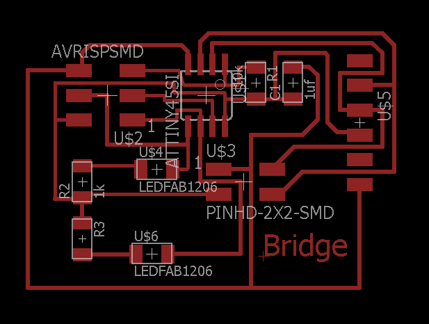
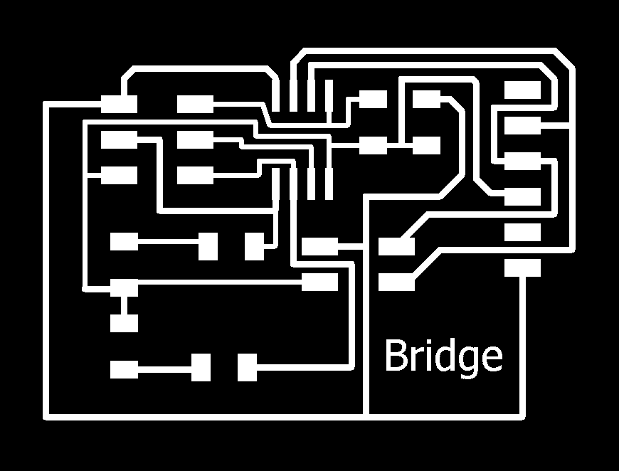
Board
Files
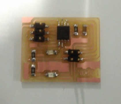
Bus node 1
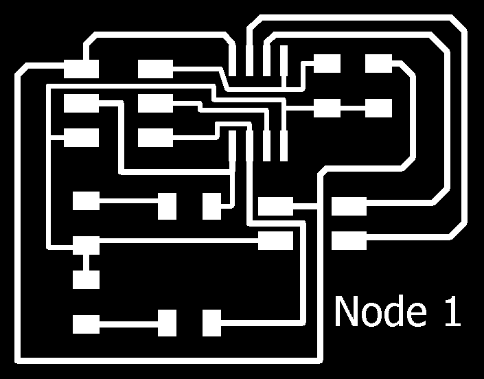
I decided to make two nodes,the first node is based on the hello.bus.45.node design with a second led added.
Schematic
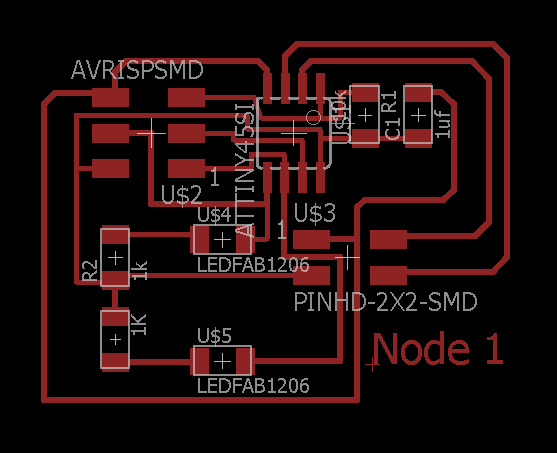
Board
Files
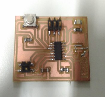
Bus node 2
For second node I decided to make Attiny 44 based board,so I made a design which is similar to the echo.hello.world board.
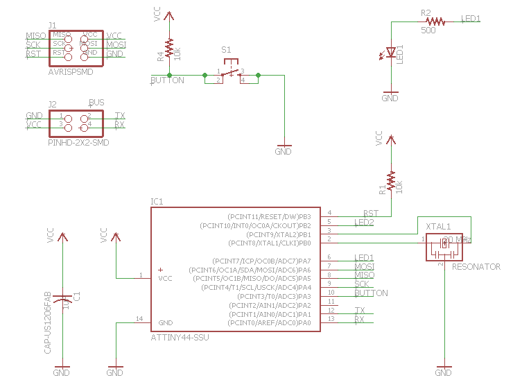
Schematic
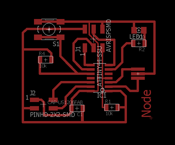
Board
Files
Then, I fabricated and stuffed the boards
Programming the boards.
First I downloaded the C program and make file of the example and modified it to add second led.For programming the bridge board, I connected it with fabisp and FTDI cable , then using codes "sudo make -f bus.bridge.45.make" and "sudo make -f bus.bridge.45.make program-usbtinty" I programmed it.For node 1 board,I connected it to fabisp and for powering the board connected it to the bridge board and programmed using same codes, only change the name.The c program for node 1 is same as that of bridge except in line 41 the node_id '0' need to be changed to node_id '1'.Then for the node 2 board I changed the pin number in the program by refering data sheet for attiny 44, and also added code for the button control.In this node id is changed to 2.Then the make file is modified for attiny 44.
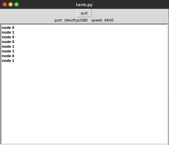
After successful programming (yay!! all boards programmed in first try.).I decided to test the communication.For it, first I downloaded the 'term.py' a python program written by Neil which helps to communicate the boards.The boards are communicate with computer using FTDI along with ribbon vable which is used to connect the boards.After the connections are made, the python program can be run using the code "pytho term.py /dev/ttyUSB0 9600".Here 9600 is the data transfer speed which is specified in the program.
Then, when I pressed 0,1,2 in keyboard at first there was no response.After some debugging I found out that there is something wrong with node 2 board.So I removed it and tried with other two,this time the leds lightup and when I pressed 0,1 numbers in keyboard and the node id is displayed on python program.The LEDs are configured in such a way that green led's blinks when there is a communication and the red LEDs blinks when the corresponding number is pressed,ie when number 0 is pressed the red led on bridge blinks and when number 1 is prssed the red led on node 1 blinks.
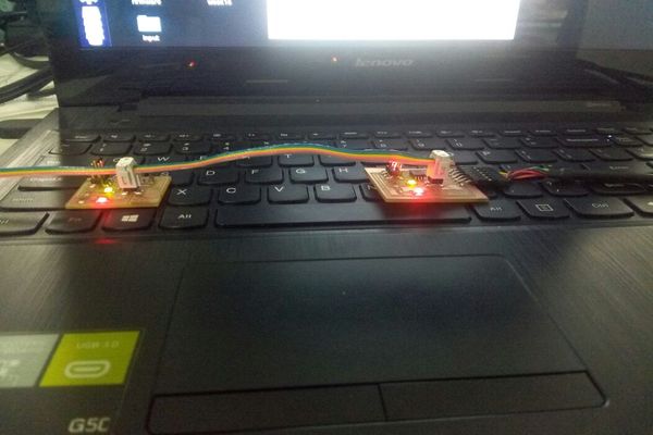
Here is a working video of it: