Riyas P.K-Fab Academy 2016
Input Devices
The assignment for this week is measure something: add a sensor to a microcontroller board that you've designed and read it. I decided to make a transmit-receive version of the step response circuit. This circuit can be use to measure esistance, capacitance, inductance, position, pressure, proximity, tilt, acceleration, humidity,touchpad , multitouch etc.
Making the Circuit Board
After refering some previous year student's documentations of input devices I decided to redesign Neil's design of step response by adding two indicator LEDs.Using Eagle, first I drew the schematic and checked the error using ERC.
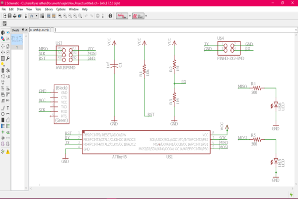
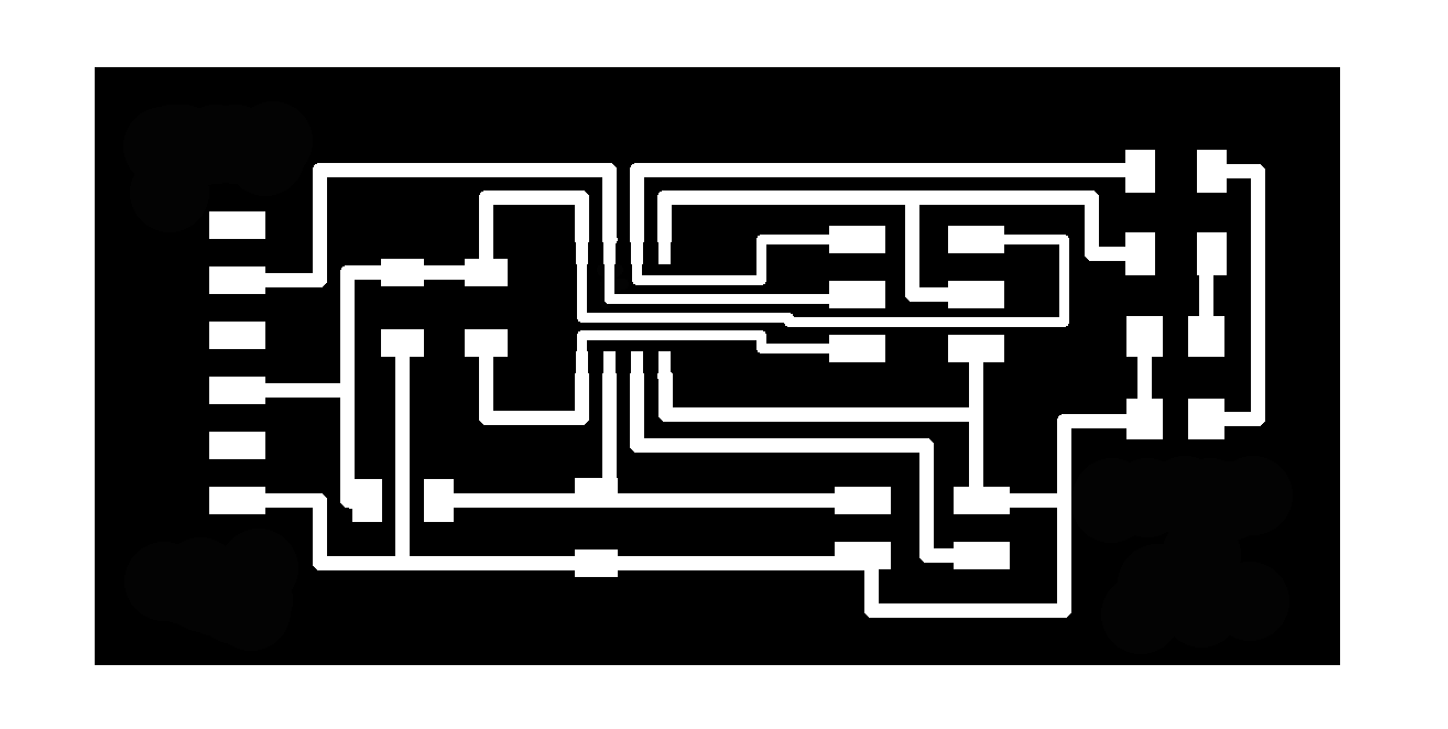
Then using switch to board option,by arranging and tracing the paths I completed the board.During tracing I needed to change the grid sizes for proper spacing.
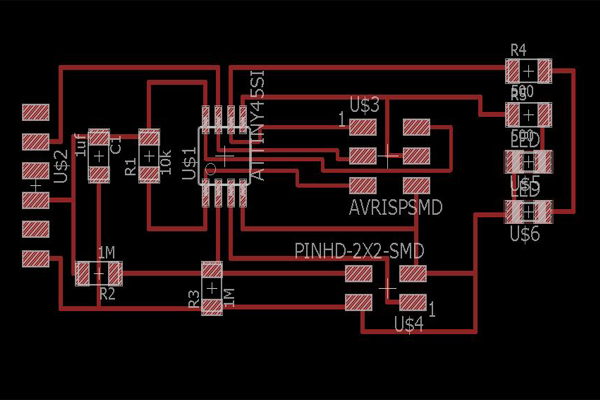
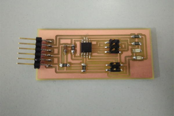
Then I milled and stuffed the board with required components.
Programming the board
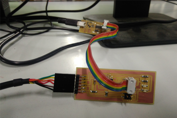
By refering some previous year student's codes, I modified Neil's program for controlling two LEDs. Then I downloaded the make,python and C files and saved to a folder.I used fabISP to program the board.Connect the board and fabISP together and also with computer.
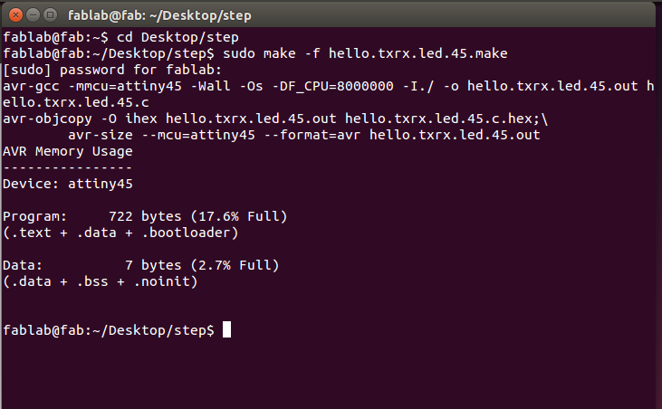
For compiling program to hex use the following code:
sudo make -f hello.txrx.led.45.make
To program the board use the code:
sudo make -f hello.txrx.45.led.make program-usbtiny
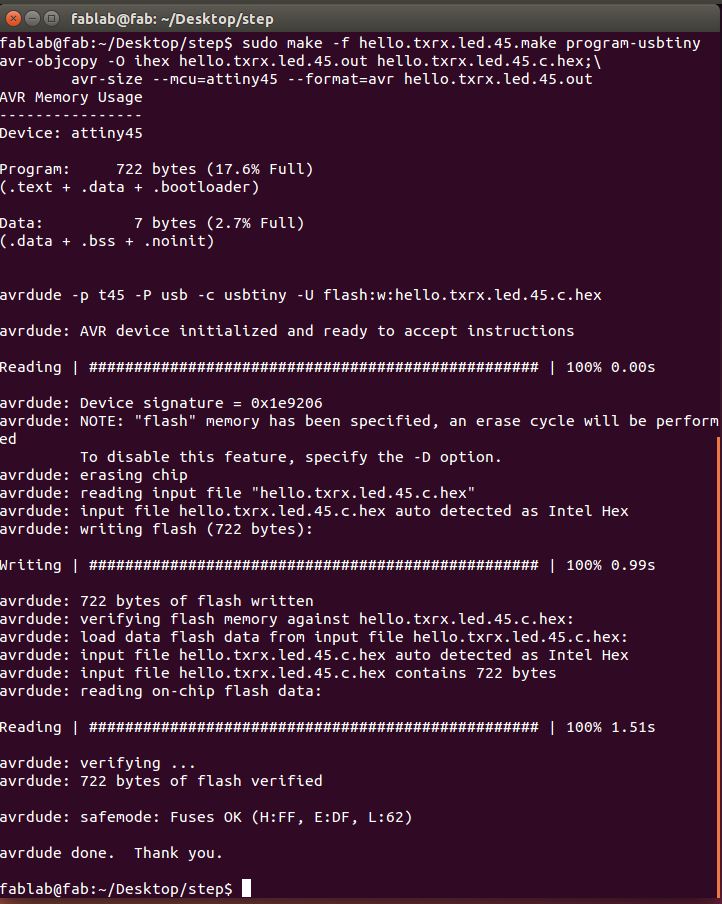
And the programming is successfull.
Debugging- a saviour
At first during programming, it shown an error 'initialization failed,rc=-1', it is a common error.This error may be due to errors in connection,board,soldering,milling etc.I first checked the connection errors using a multimeter, it was fine.Then I looked for bad soldering, nothing there.After some time of frustration I flipped the 6 pin cable, and it magically worked.So, always before make another board you should debugg, it may fix the problem.
Testing
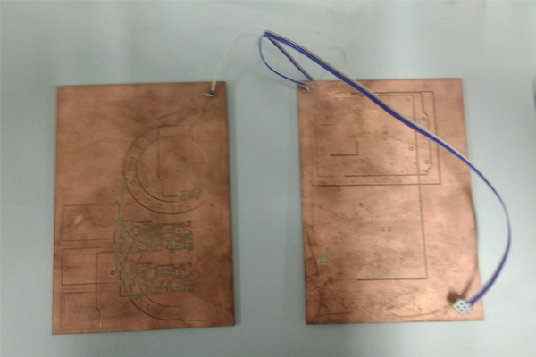
I made a four pin ribbon cable and connected it to the board, then I soldered the RX and TX of the ribbon cable to two different copper boards.
Before running the python program you need to remove connection to programmer before this.Then I used the example Python program and the FTDI USB to serial cable to communicate with the circuit and display the analog information.To run python program use following code :
python hello..txrx.45.py /dev/ttyUSB0
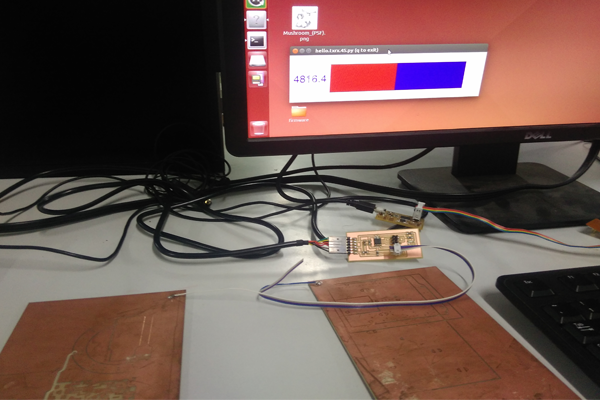
Reading- without pressure.
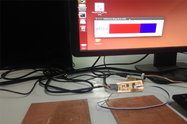
Reading- small pressure(value>5000), red led is turned on.
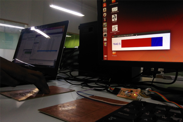
Reading- more pressure(value>7000), both red and greens leds are turned on.
Here is a video of it:
Files
- Schematic in eagle format.
- Board in eagle format.
- Board in png format.
- Interior in png format.
- C program.
- Make file.
- Python program.