Assignment
- redraw the echo hello-world board.
- add (at least) a button and LED (with current-limiting resistor).
- check the design rules, and make it.
Design
The weeks assignment was to redraw and make changes to the Echo Hello World Board.
There are 2 changes to make: Add a Button and an LED.
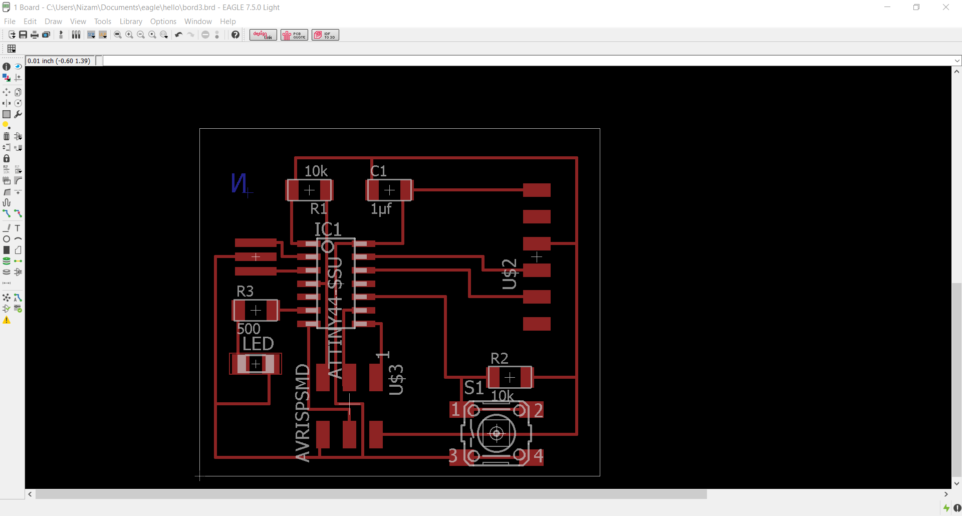
This year, We were told to design the echo hello world board from scratch. So we needed to design and place all
the components, not just the button and LED. I decided to use the Eagle software after some research.
Download link for Eagle: click here
The link contains download file for windows,linux and mac.While Designing a board in eagle, Both the schematic
and board views of the required board need to be open. This willl maintain a connection between the two and any
changes made to one will reflect on the other.
Here are the Tutorials for eagle:
Eagle Schematic Tutorial
Eagle Board Tutorial
The components required for making the Board are:
- 6-pin programming header
- microcontroller
- FTDI header
- 20Mhz resonator
- 2 pullup resistor(10k)
- current limiting resistor(499ohm)
- capacitor
- Button(OMERON swich)
- VCC
- Ground
- LED
Here are 2 library files to add, which was made available from fab archive and Neil: fab.lbr ng.lbr
copy both files to the installed directory. In windows, the path is: C:/program files/Eagle/lib.
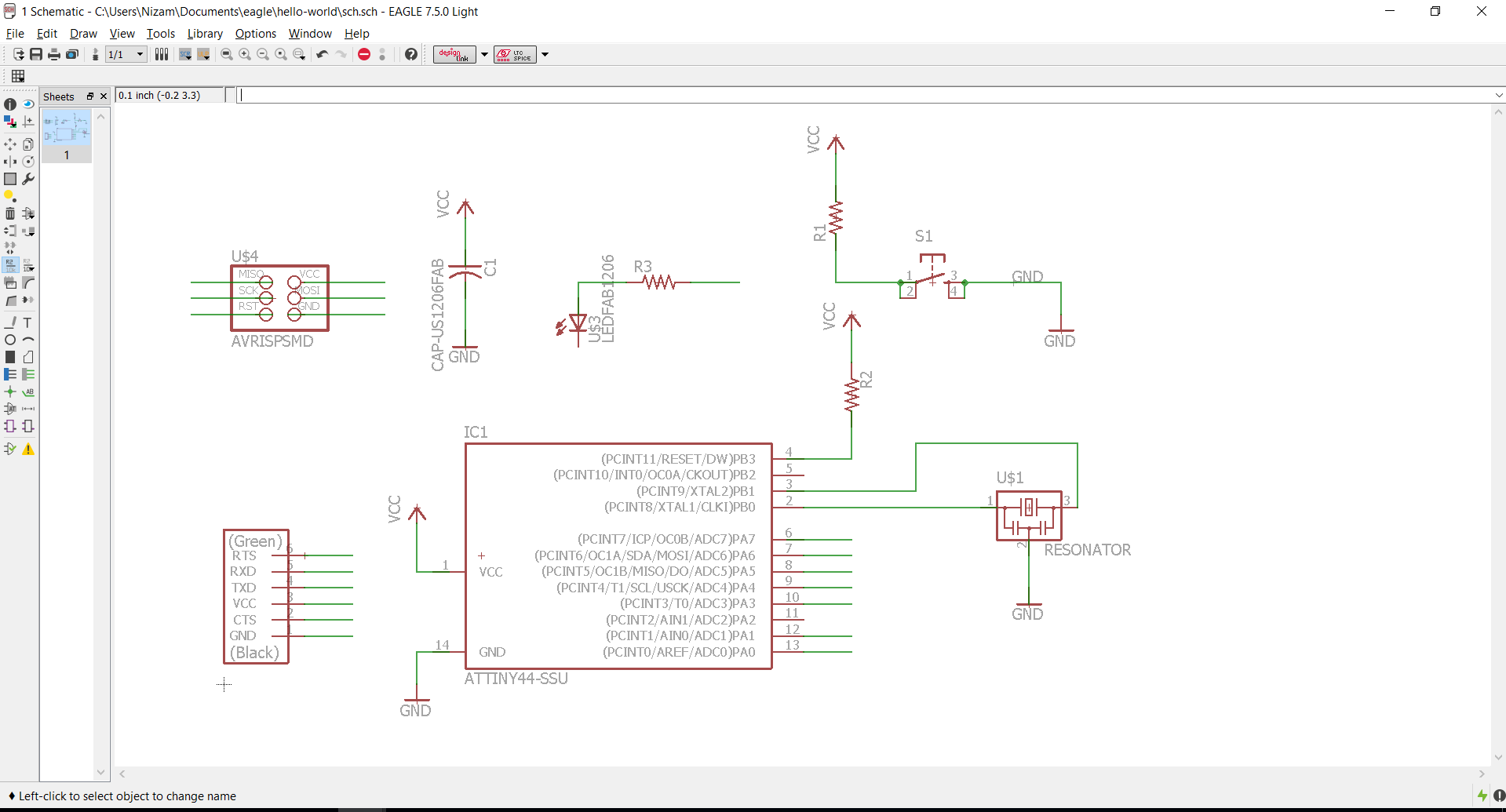
Steps for schematic and board:
- Add all the required components.
- place the components in the appropriate places.
- create connections between the appropriate cmponents using the net tool or command.
- Name and label each connection.
- Check for errors and fix if there aare any. Use ERC(Electrical rule check).
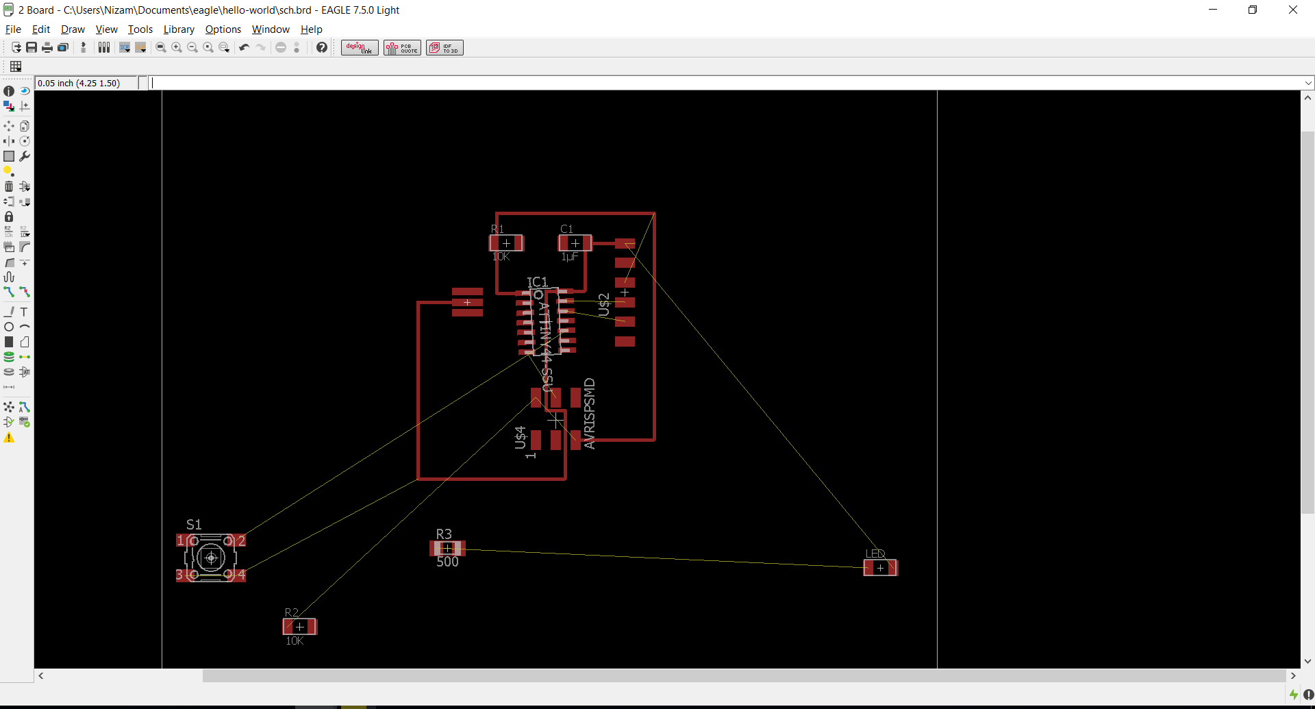
- Switch to the board view. Yellow traces will show the connection between components.
- Drag and place the compnents inside the border. The palcement of the components must be at an appropriate distance from each other.This is for good soldering space.
- Route the traces between the components. Autoroute is not adviced beacause its will mess up the route traces in some cases.
- verify the position and connection using DRC.
- For exporting interior for milling, first select only the 'top' in the layer list and deselect the rest.
- select the 'image' option in the Export menu. it will automatically save as .PNG
- Set the resolution to 500 dpi and select the monochromatic option.
- Export.
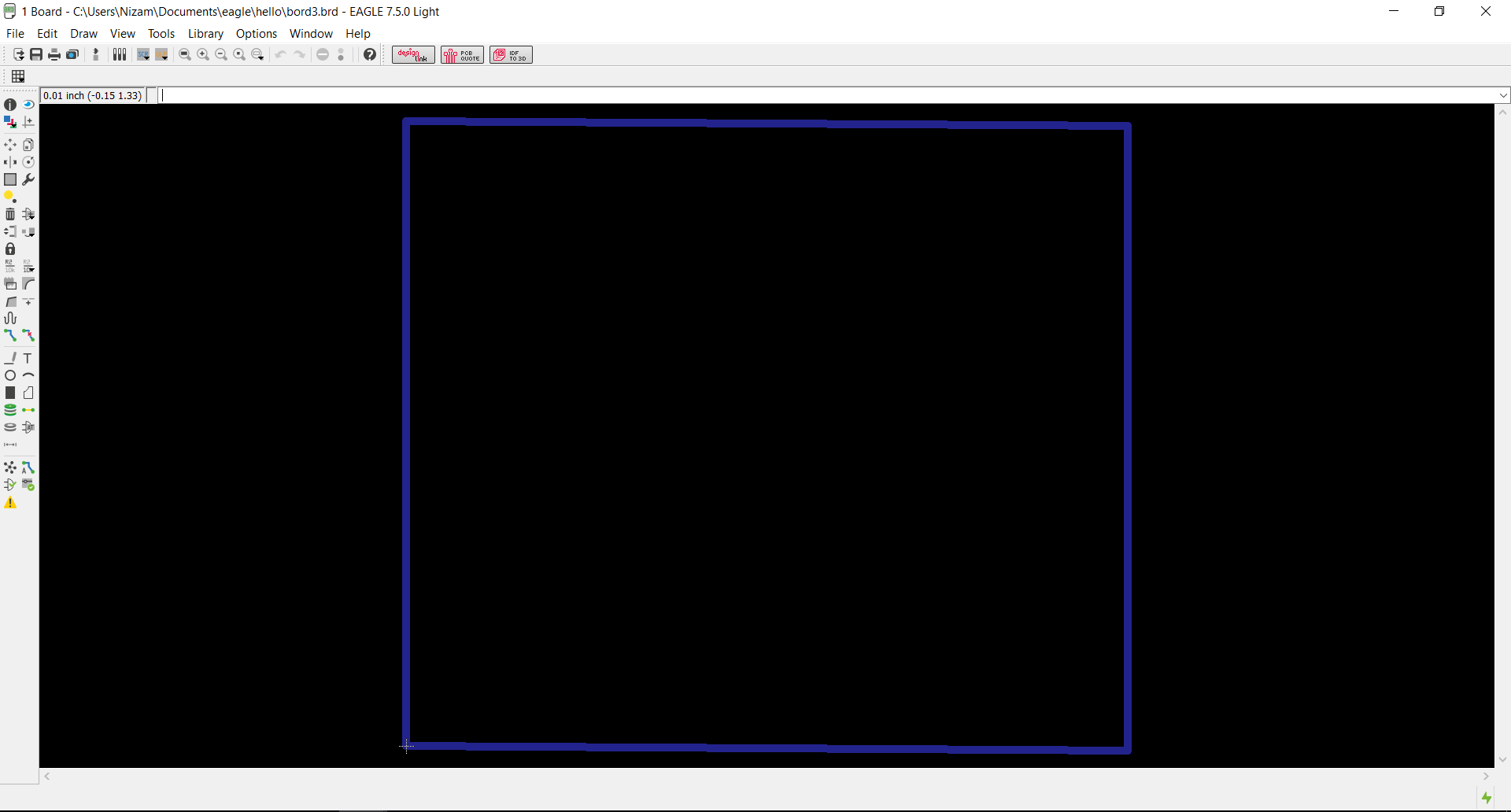
- For exporting exterior for milling, select any layer in the layer menu other than 'top', preferably the unassigned layer.
- Draw a border in that layer and then export the board as .png using the above steps.
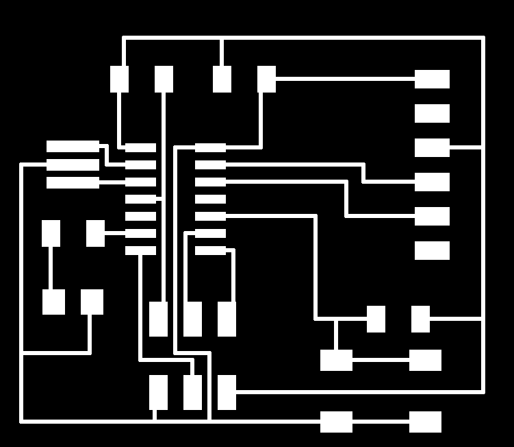

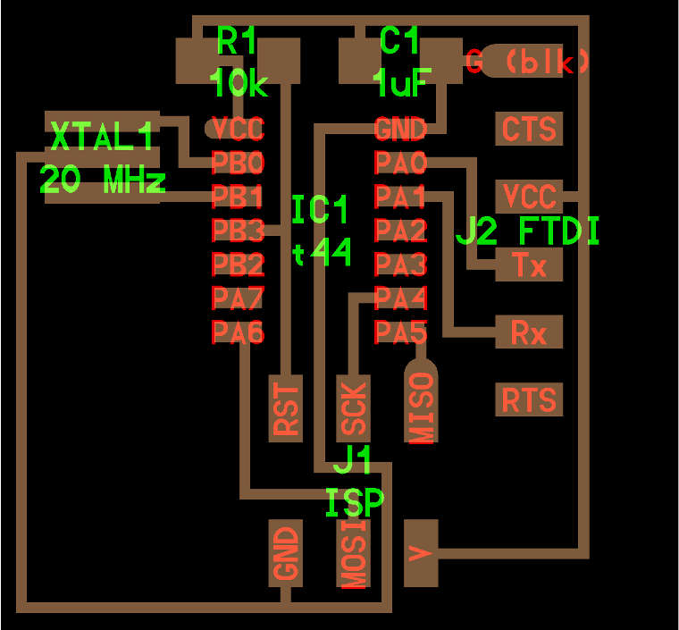
Here is a pic of the board:
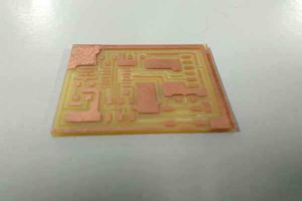
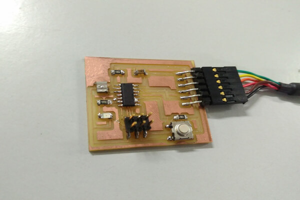
The next step was stuffing/soldering the compnents into the board.For this, i followed the same steps steps as i had in the electronics production week(week4).The soldering process took me 1 hour to complete.
Here's a pic of the soldered board-