AQUAFEED
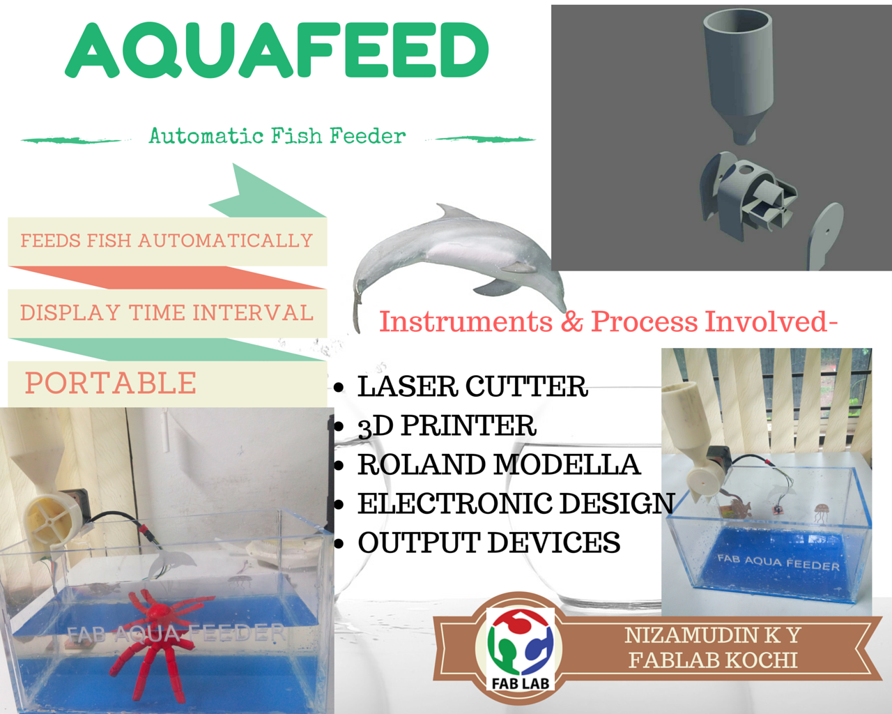
Aqua feed is an automated fish feeder with LCD display.It incorporates various techniques such as :
- 3D printing
- Laser Cutting
- Electronic Design
- Networking
Electronic Design
I decided to start with the electronic design first, since this would be the most difficult part other than 3D designing.
On the electronics front, the main functions i had in mind was:
- Main board
- LCD Display board
- Network connecting main board and LCD display
- Interface to computer
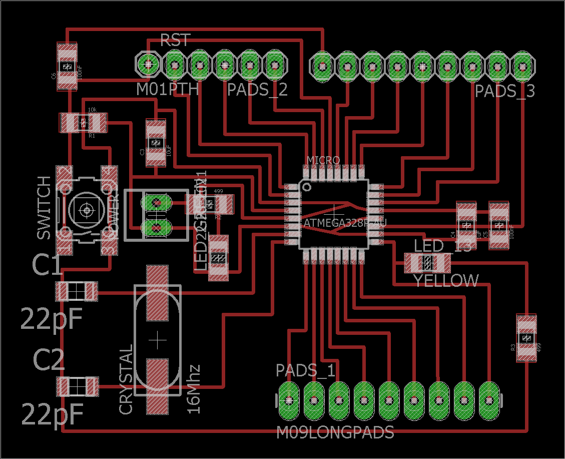
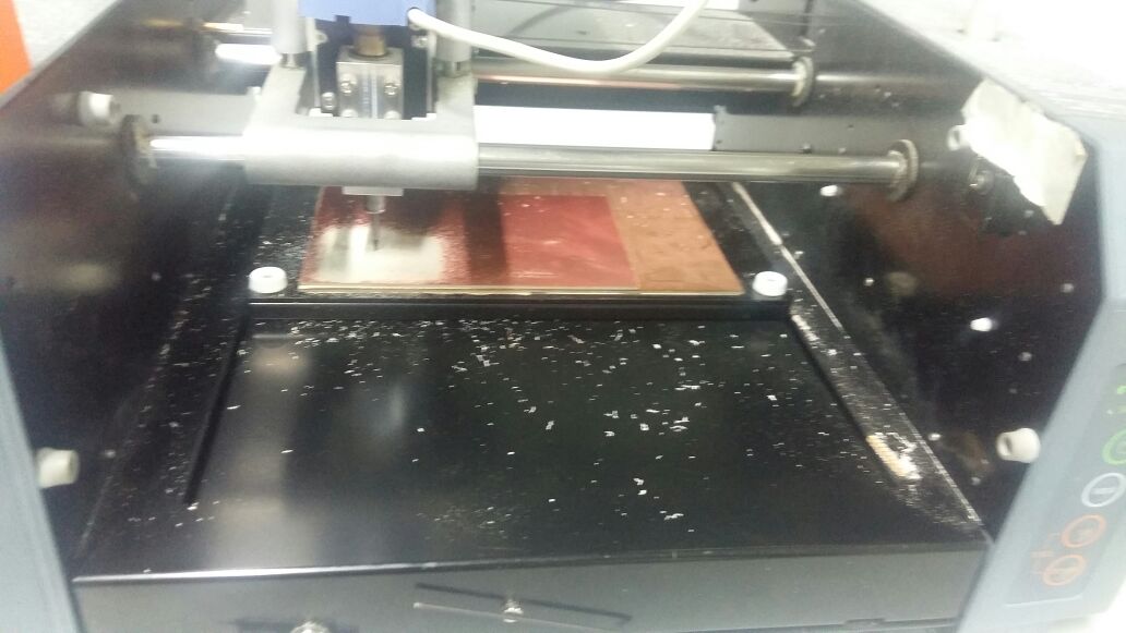
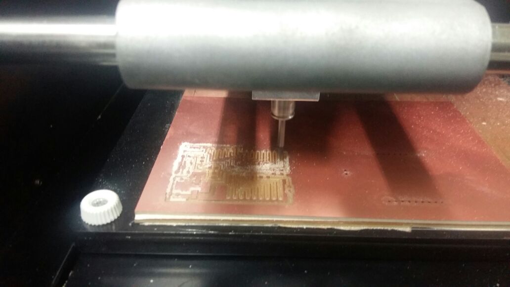
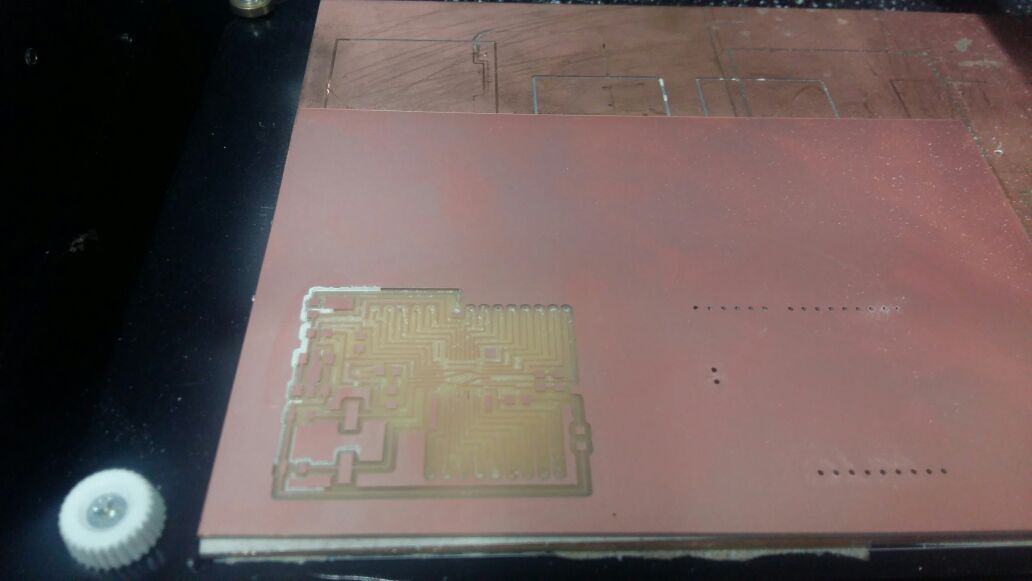
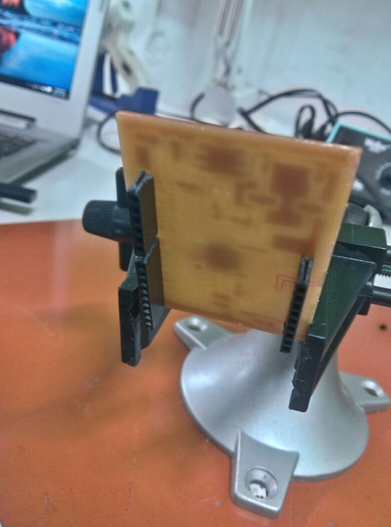
Since the board was perfect for my purposes, i milled it without making any changes.
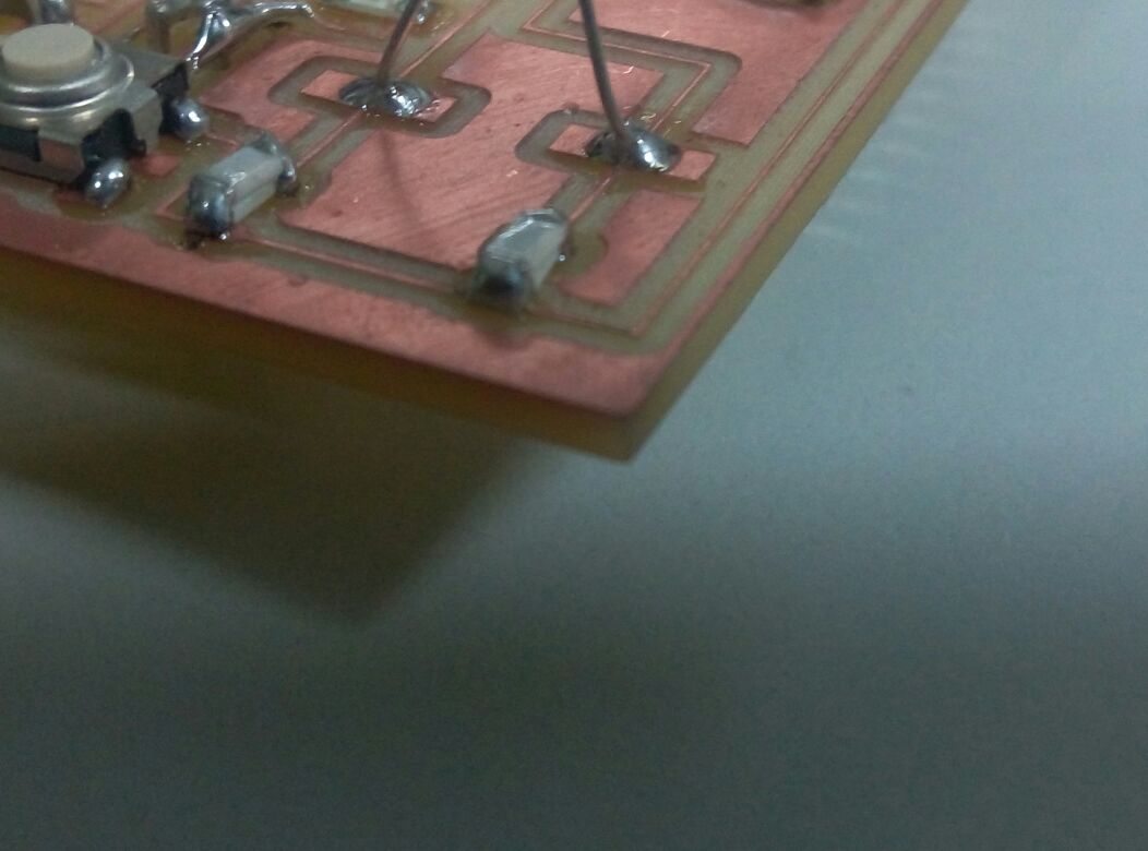
Next came the soldering of the board. This was my first time soldering atmel 328p so it was difficult.The pins were small compared to Attiny IC's.The first board became a mess during soldering so i had to mill another board.This time i was more carefull to solder the IC and was succesfull.
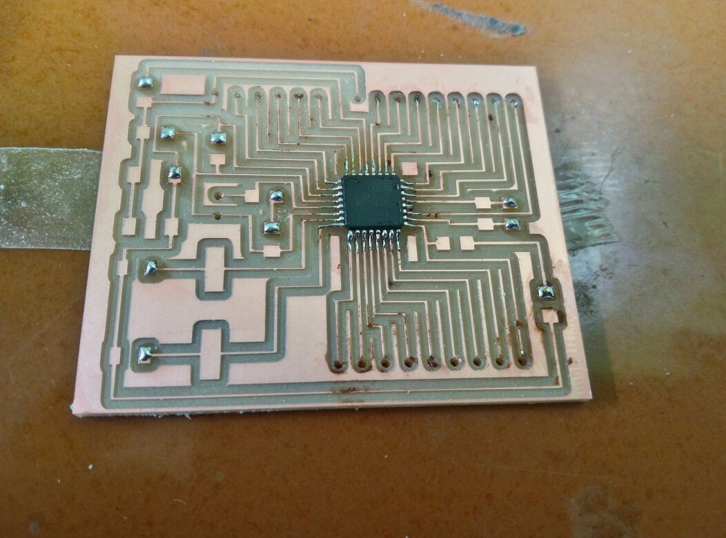
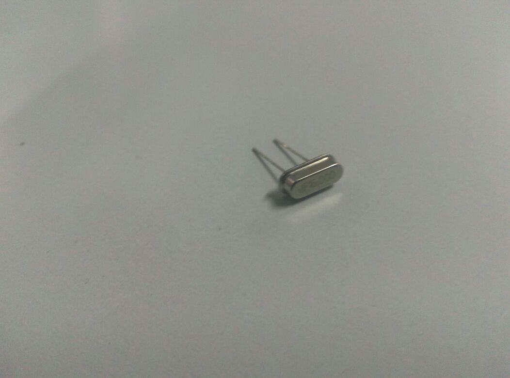
There were 2 components that was not available at our lab- 16mhz crystal oscillator and 22pf caopacitors.smd's were not locally available so i bought a normal oscillator. For the 22 pf capacitors, i soldered 2 10pf capacitors in parellel.
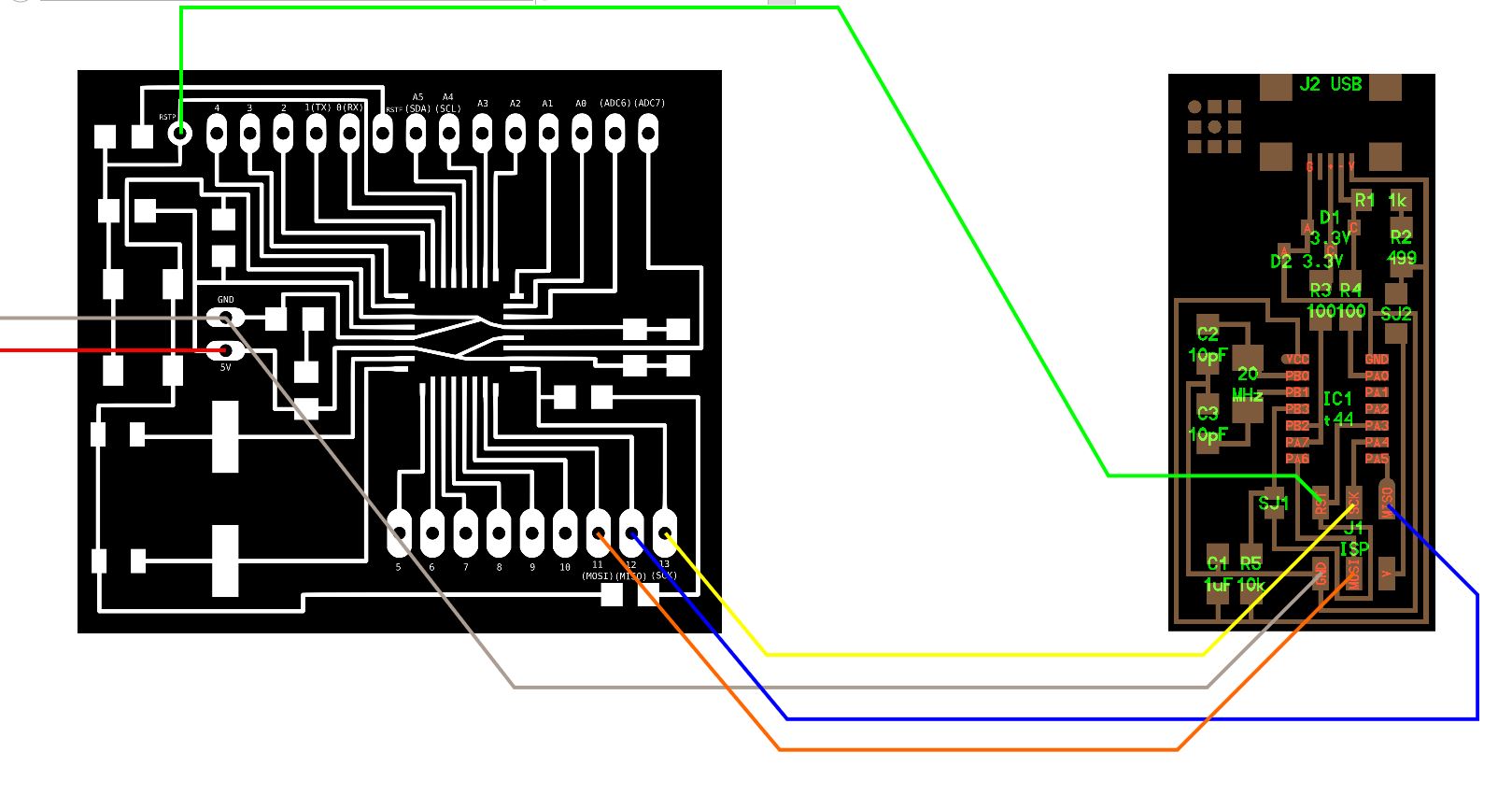
Now that the board was fully soldered, next step was to burn the bootloader.The bootloader can be burned using either an arduino or a fabISP.I used the fabISP.
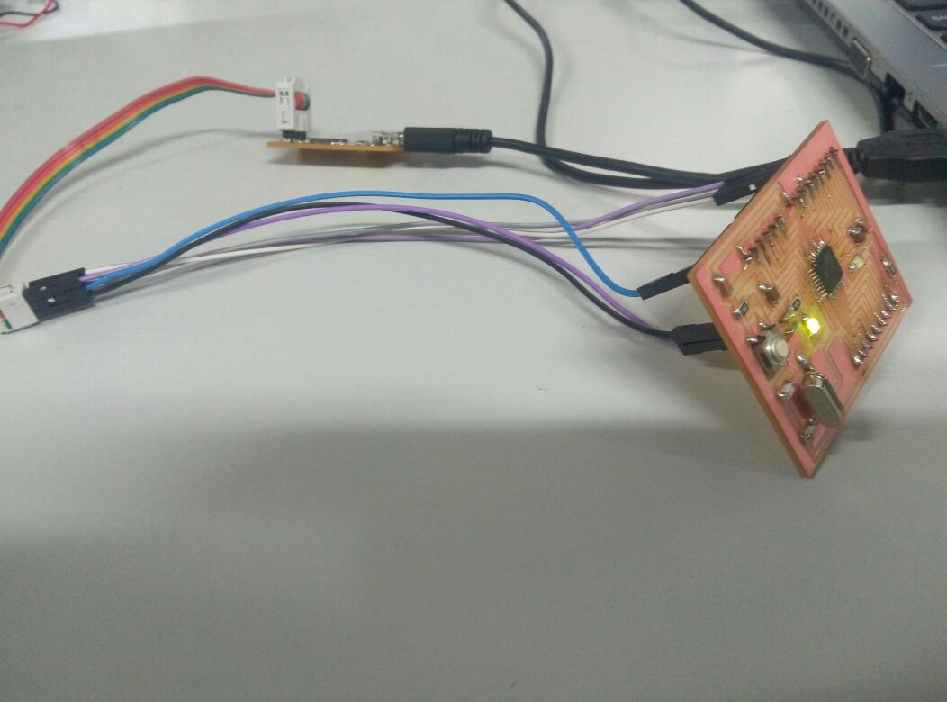
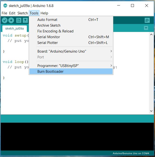
If the bootloader burn is succesfull,it means that the board is ready for programming.Now i needed to make sketch the required network connections and serial communication between the boards before i can begin the programming phase.
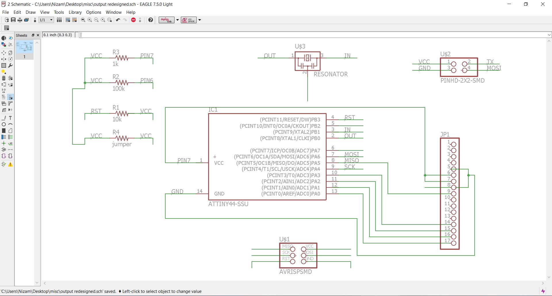
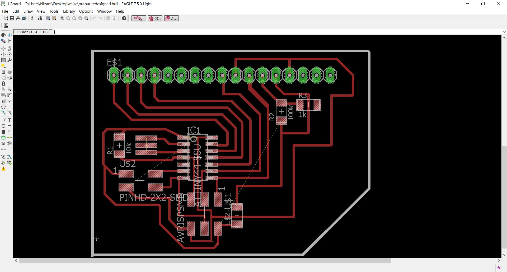
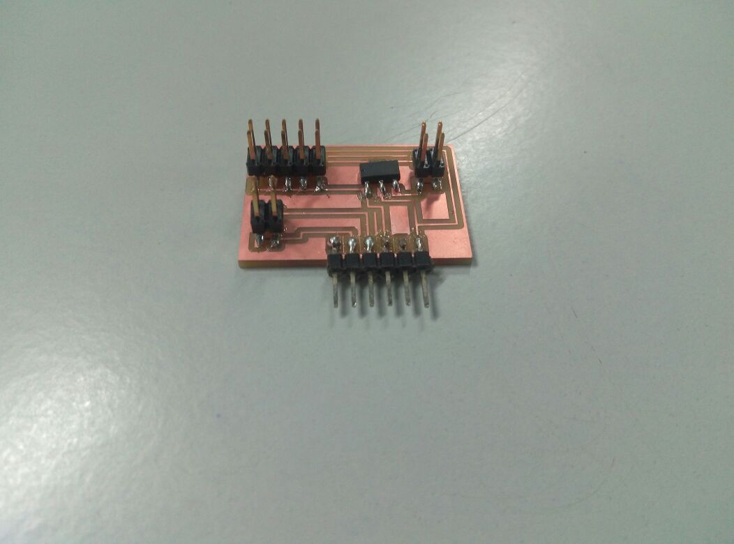
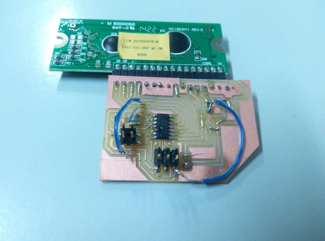
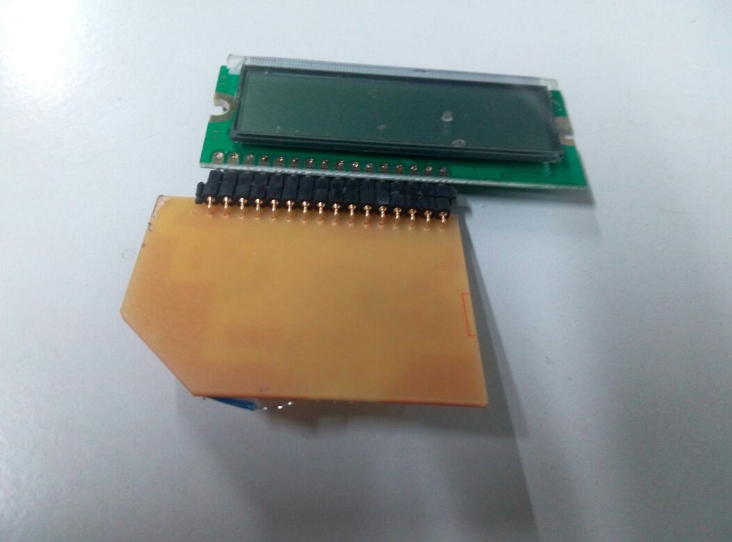
Once the main board was completed, I decided to create the LCD board next.This board only needed to connect the lcd display and pins for serial data transmission.I created the board design in eagle since i was familiar with the software.
Laser Cutting
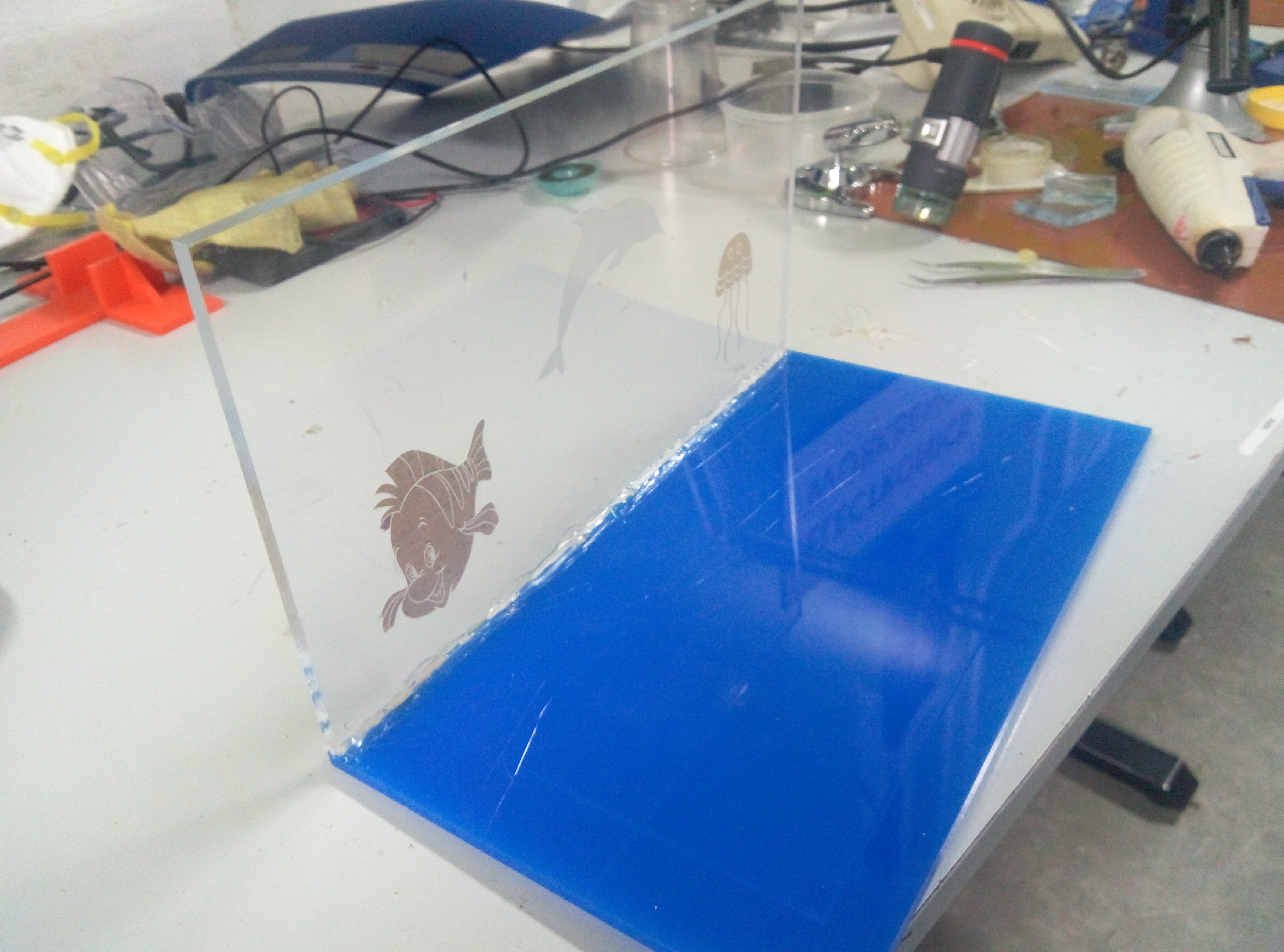
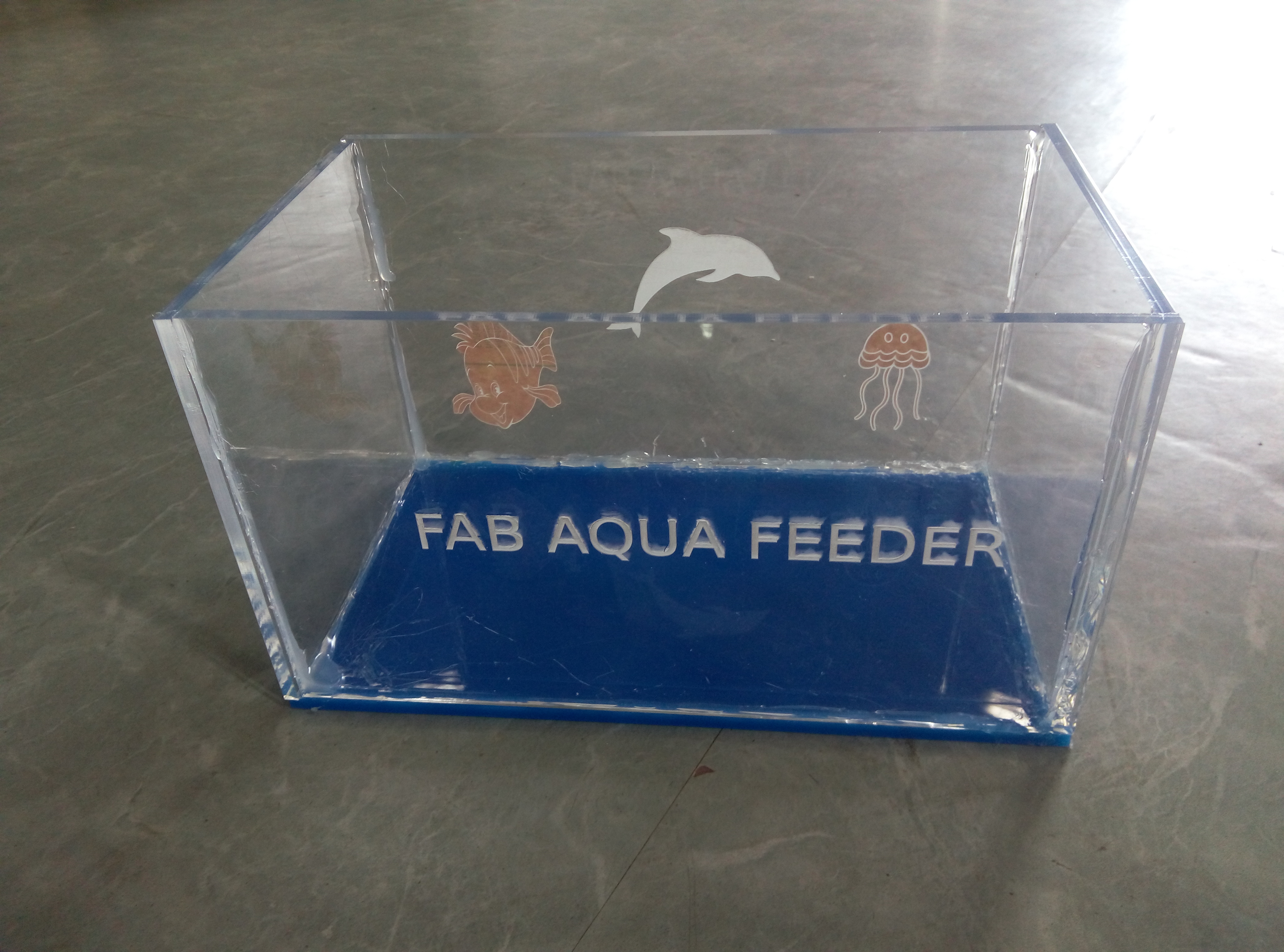
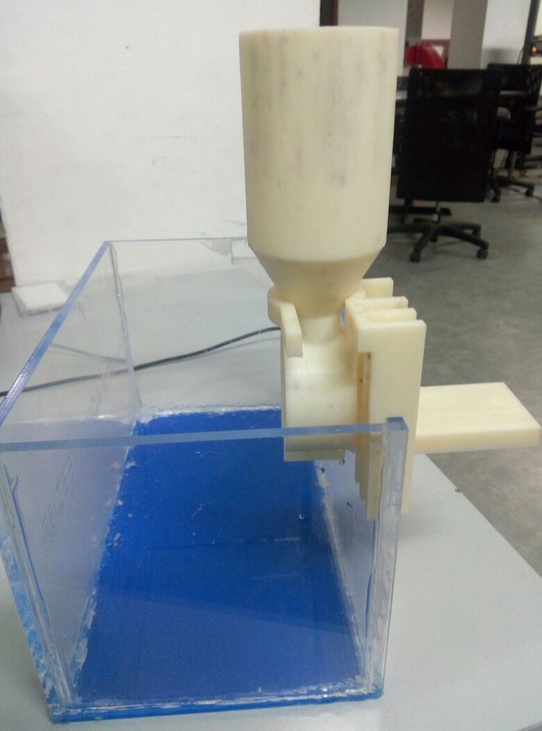
I made the fish tank using acrylic. We had 6-inch white acrylic available here so i used it.For the base, i used blue acrylic, since it would give the water a bluish hue and would go well with the blue LED's i was planning to add.
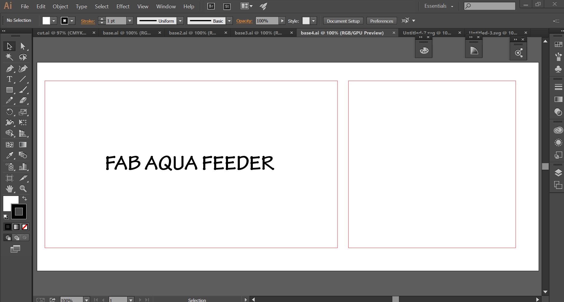
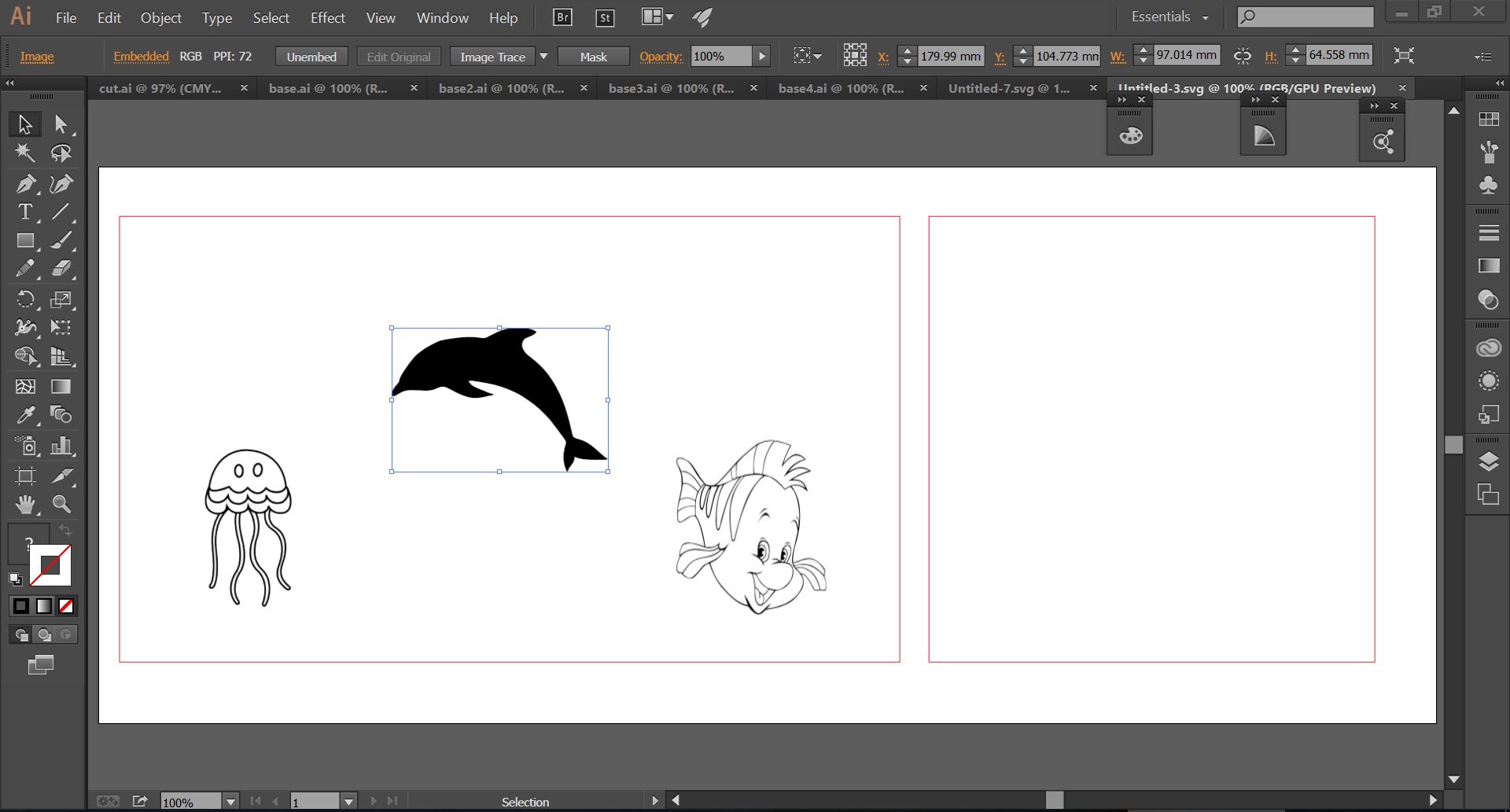
Designing was done using Adobe Illustrator.The design was pretty simple. Since the tank needed to be glued to prevent leakage, pressfit design was not an option.So i cut plain rectangles of size 35*20cm and 20*20cm for the base and 4 sides.
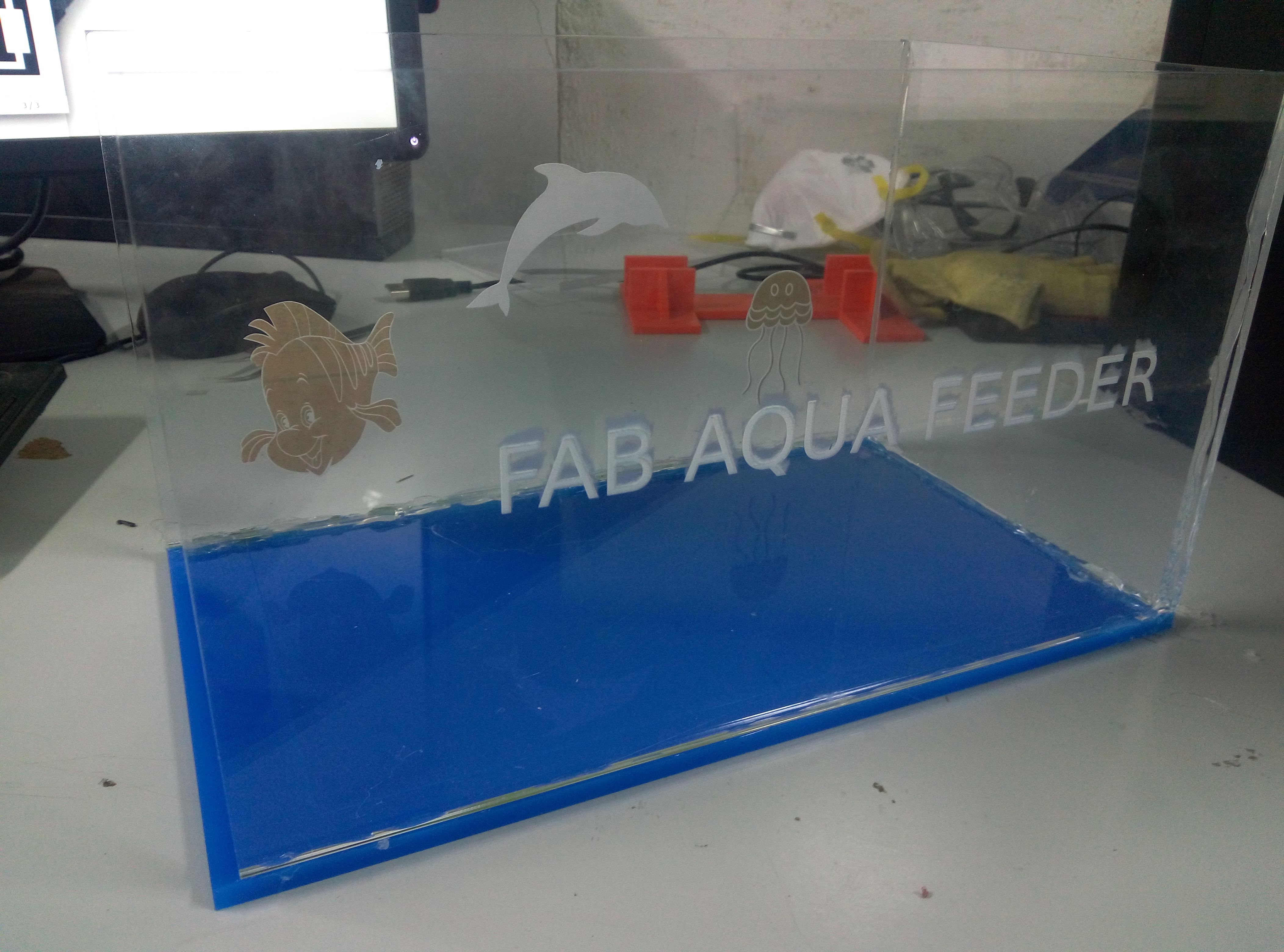
Also added some designs to the acrylic.Wanted to give a fishy theme.
After i laser cut the acrylic pieces, next step was deciding how to join them. Usually, aquariums are fitted using a special glue cement, which would take more than 24 hours to dry.It was also difficult to obtain.So i used the glue gun in fablab along with industrial super glue.
3D printing
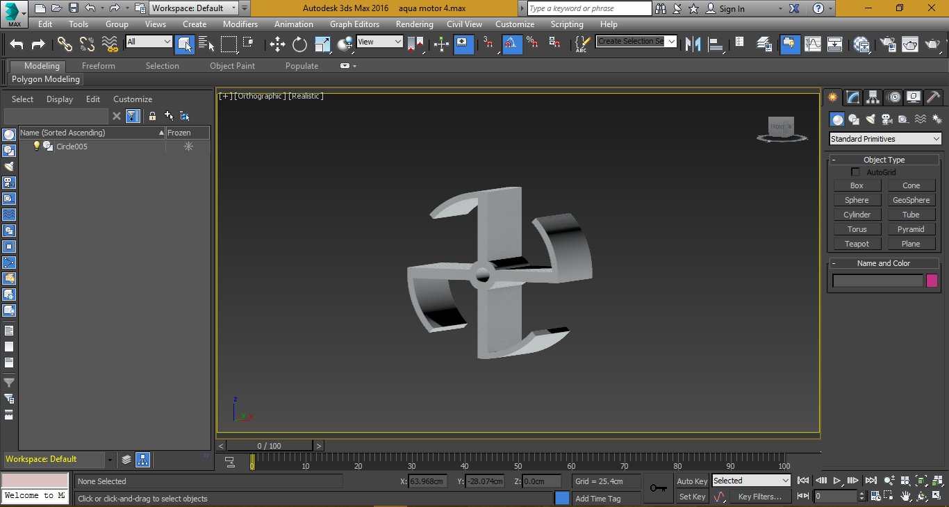
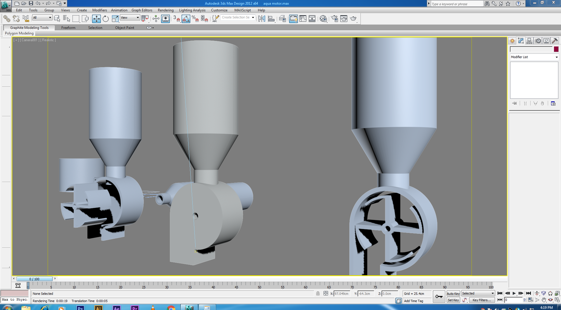
3D printing was to play an important role in making the feeding mechanism. I had designed all the parts to be 3D printed. I used both 3ds max and solidworks to make the designs.
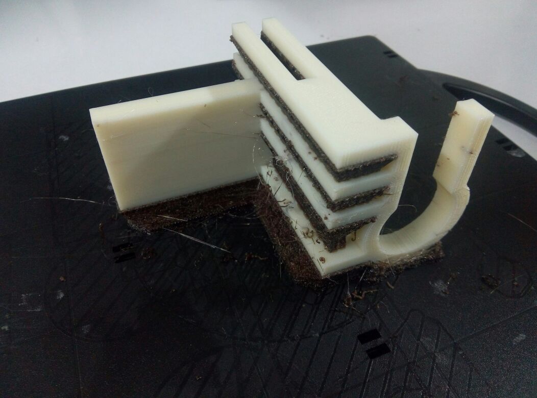
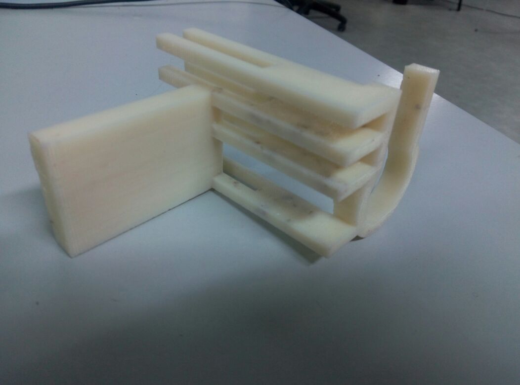
FIrst i designed the feeding mechanism.
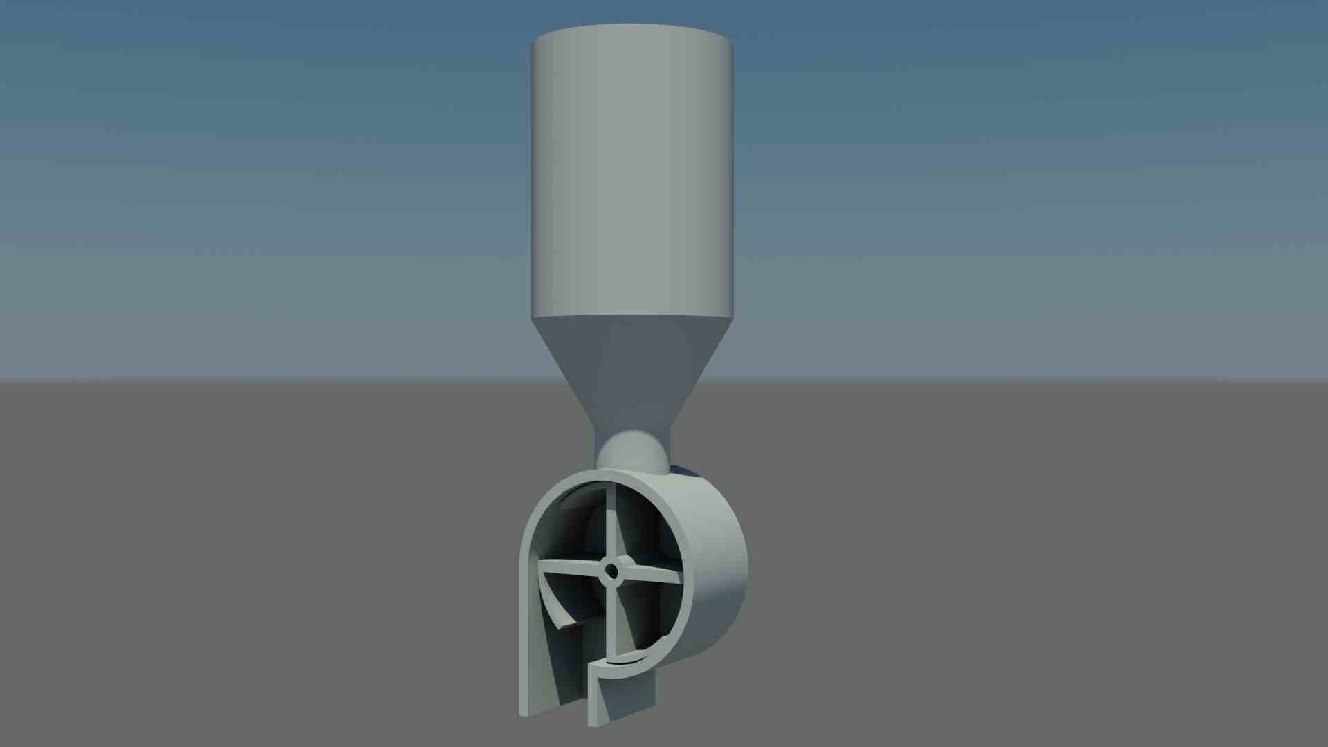
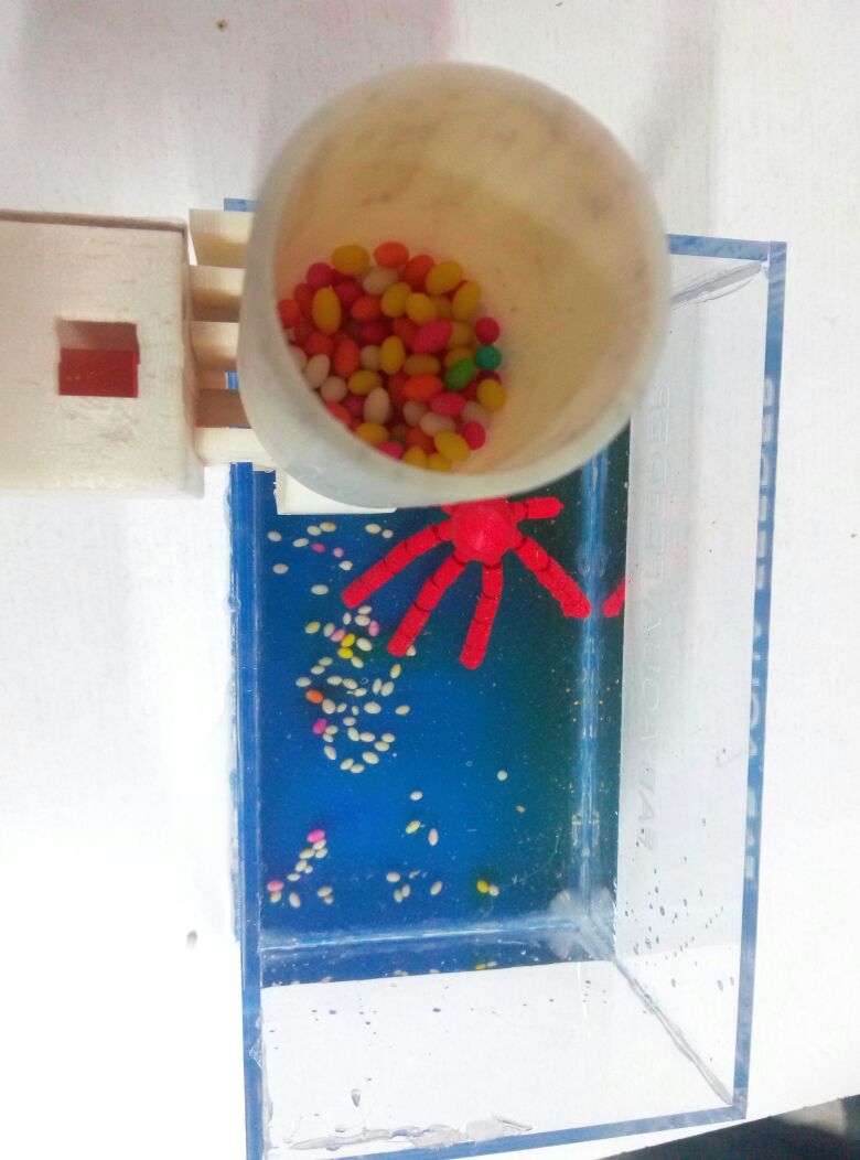
The fish feed will be stored in the upper cylindrical section.The wheel in the bottom section is connected to a servo motor which will rotate for a fixed angle during a fixed interval of time.The speed of rotation will be used to regulate the amount of food dispensed.This feed in the wheel be dispensed to the fish tank.
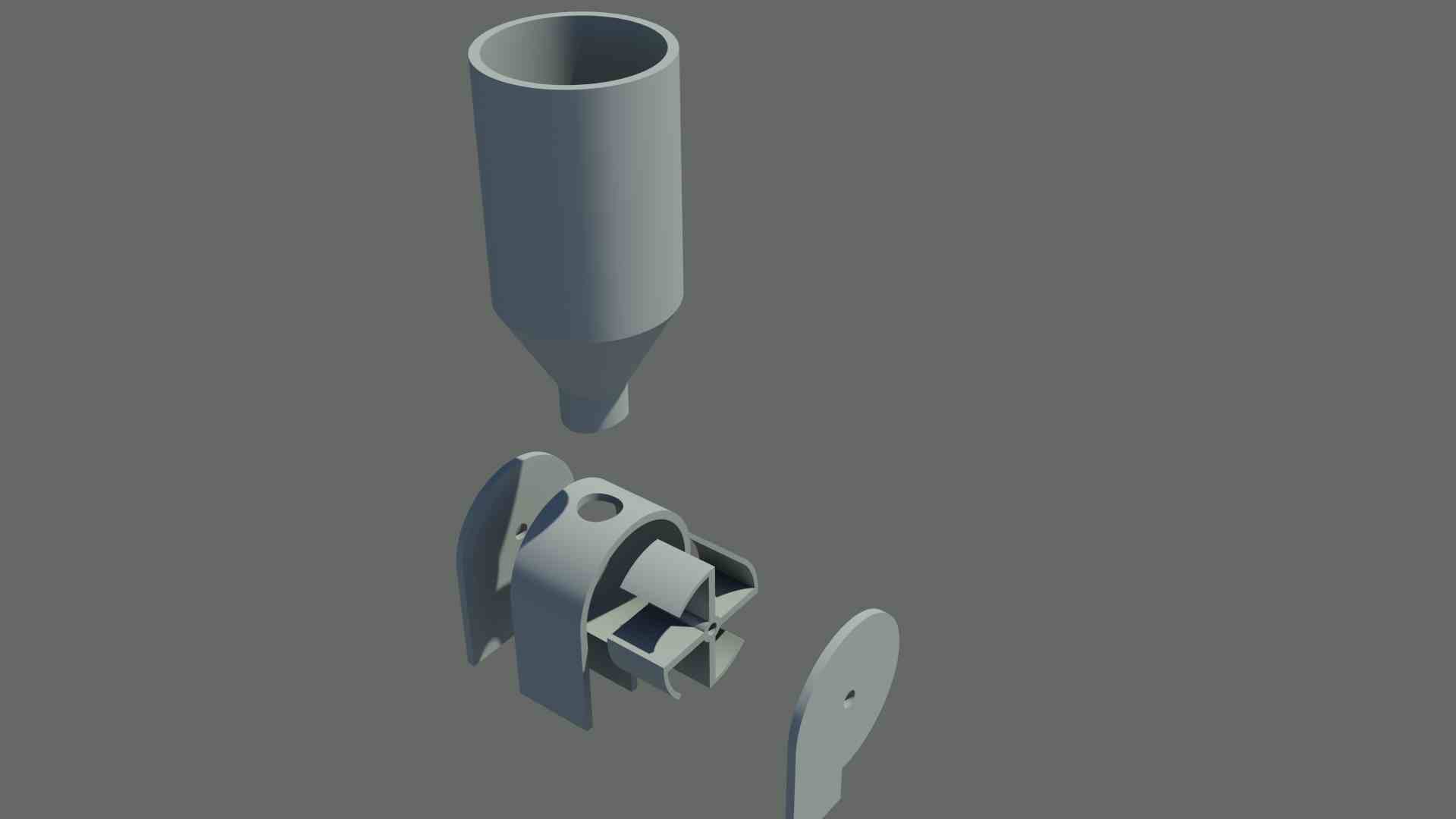
The part after 3D printing was in perfect measurements.The clearence between wheel and body was 2mm. This would allow the wheel to rotate freely within the body in a good fit...
3d view of mount in sketchfab:
Assembling, Programming & Testing
First i need to program the individual components.The main board is responsible for motor control. The LCD board will be responsible for displaying time. The time interval for feeding will be set during programming for now. But i plan to add an compuer interface that will allow the user to set the time interval without having to edit the code everytime.
The display board will check the time continuosly and when it is the preset time, the board will send a command/message to the main board. Upon recieving this message, the main board will rotate the motor to a fixed degree.The user interface must occur between the display board and the computer.
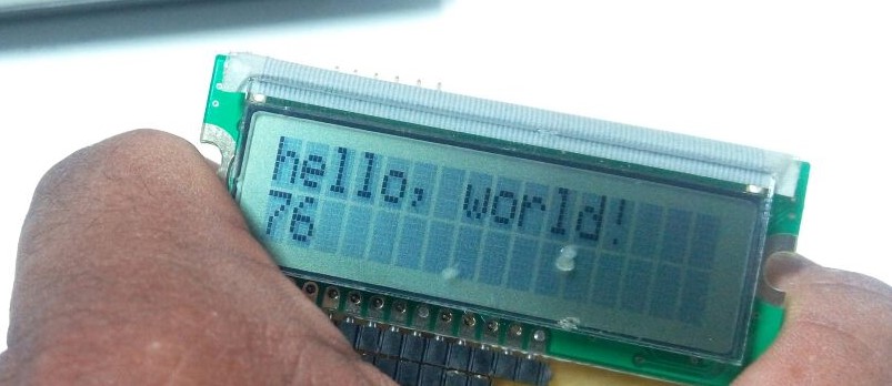
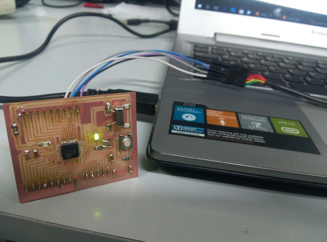
First, i decided to check the LCD display working.For this, i used a simple 'Hello world' program from the arduino example sketches.
Now that i knew the board was working, it was time fro programming it.Since i wasn't using a real time clock(tried and failed to make one, dont have time to retry), i used time library to make the time functions.The time libraries of arduino have become obsolete, however they have provided a link to some working libraries in their site. I utilised the libraries of teensy which was arduino compatible after installing teensyduino.After obtaining the time libraries, i wrote a code to set the time and check for the time interval. I used a Timeralarm to set the feed time. This would enable it to send a message to the main the board whenever the alarm is triggered. The main board controlling the server can then activate the feed mechanism.
while programming this, i encountered a block. For the program, i had used multiple libraries, and the IC i had used was attiny44.
While programming, an error showed saying that the sketch used more memory than was available. I couldnt load any libraries with Attiny44 due to this memory problem. I realize now that i should have used better IC like atmega-328p, but no time now. I had to do with what i had. so i removed all the timer libraries and wrote old fashioned code to include time.this was working, however i plan to make a new board when i have time, even if after the fabacademy!!
Next step was programming the main board. The main fuction is to listen to commands/message from the display board, so that it can activate the motor.
when i expand the project to integrate the temperatue and PH sensors, the main board board will be used to control and intergrate all 3 input and output devices.First i tested the motor:
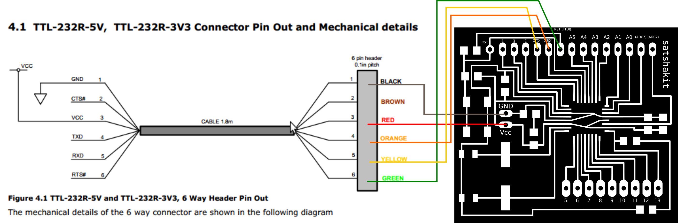
Then i programmed the main board(satshakit board) using a FTDI cable. The connections between FTDI and main board(program using arduino as ISP)-
Network
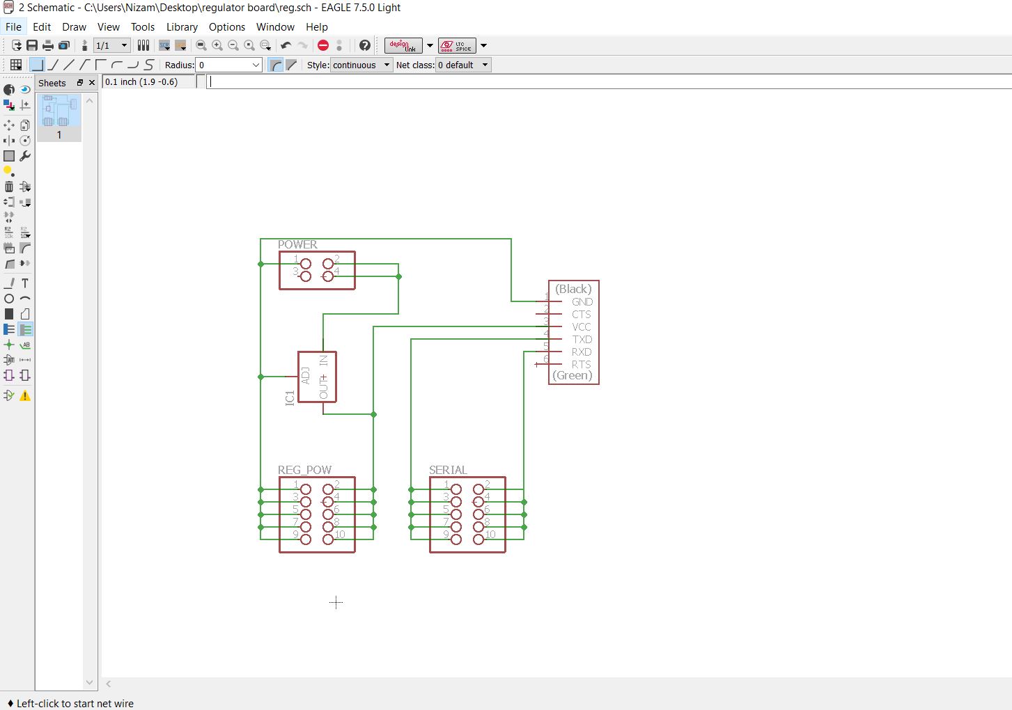
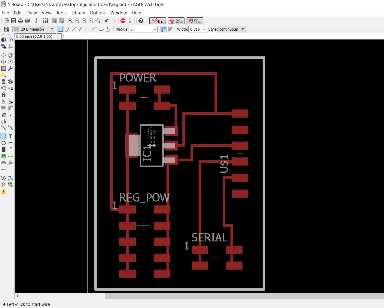
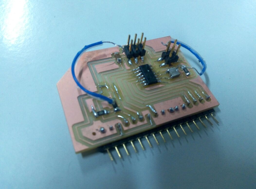
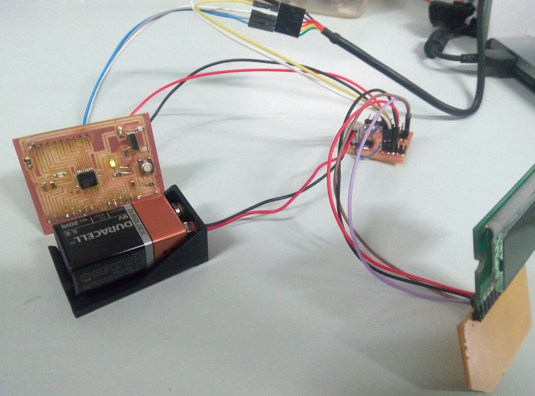
Now that the programming phase was done, it was time to make and test the network connection between main board and display board. Since the sathshakit board only had one pair of serial transmission pins(i would require 3 pairs to also include the interface), i used the extra pins available in the regulating board to act as a kind of breadboard ports.
This board had another important funtion also.It would also contain a power regulating circuit. This is required to provide regulated 5v to both the main board and display board from the 9v battery or the power adapter, whichever i chose to use.
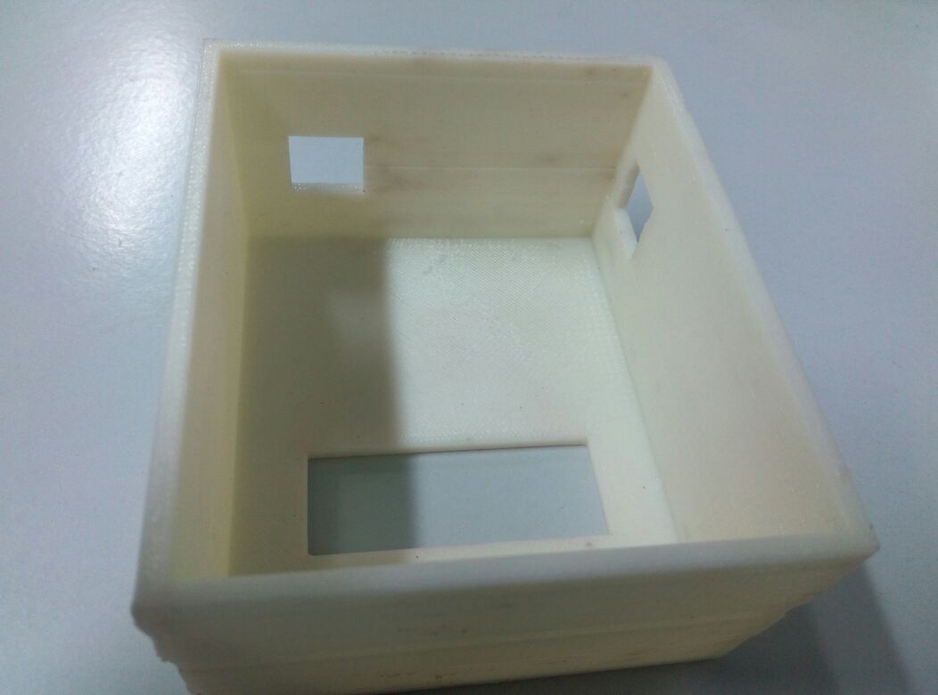
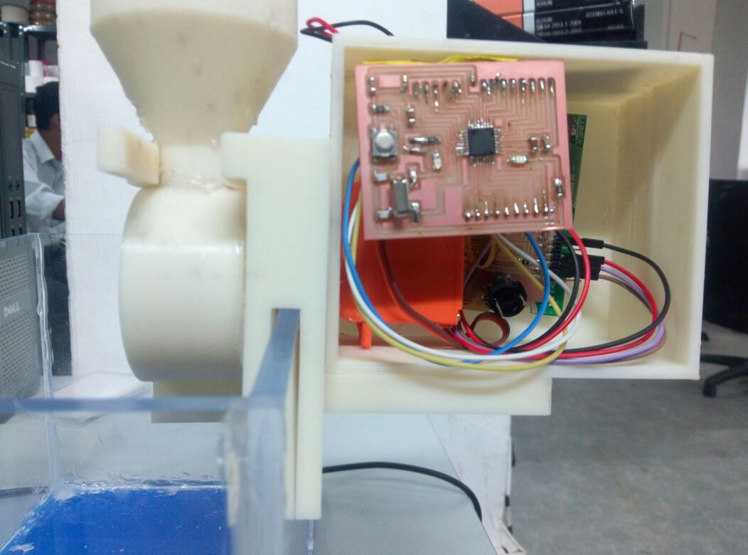
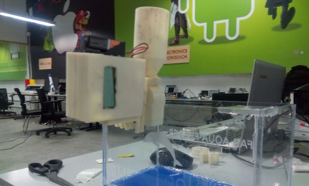
After making the network connections and making sure that all was working accodring to plan, all that remained was to mount the electronics assembly in the containing box and connecting to the motor.Here i encounetered some problems.the box i 3d printed wasnt big to contain the full assembly comfortably. I had miscalculated the space needed for the full assebmly.
However i didnt have enough time to design and make another box. So i used double tape and cramped all the components inside the box. It was wild luck that none of the connections broke.Since i didnt have enough space left, i decided to mount the battery pack on the topside.
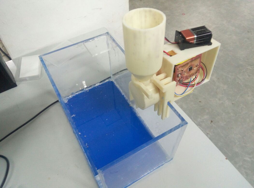
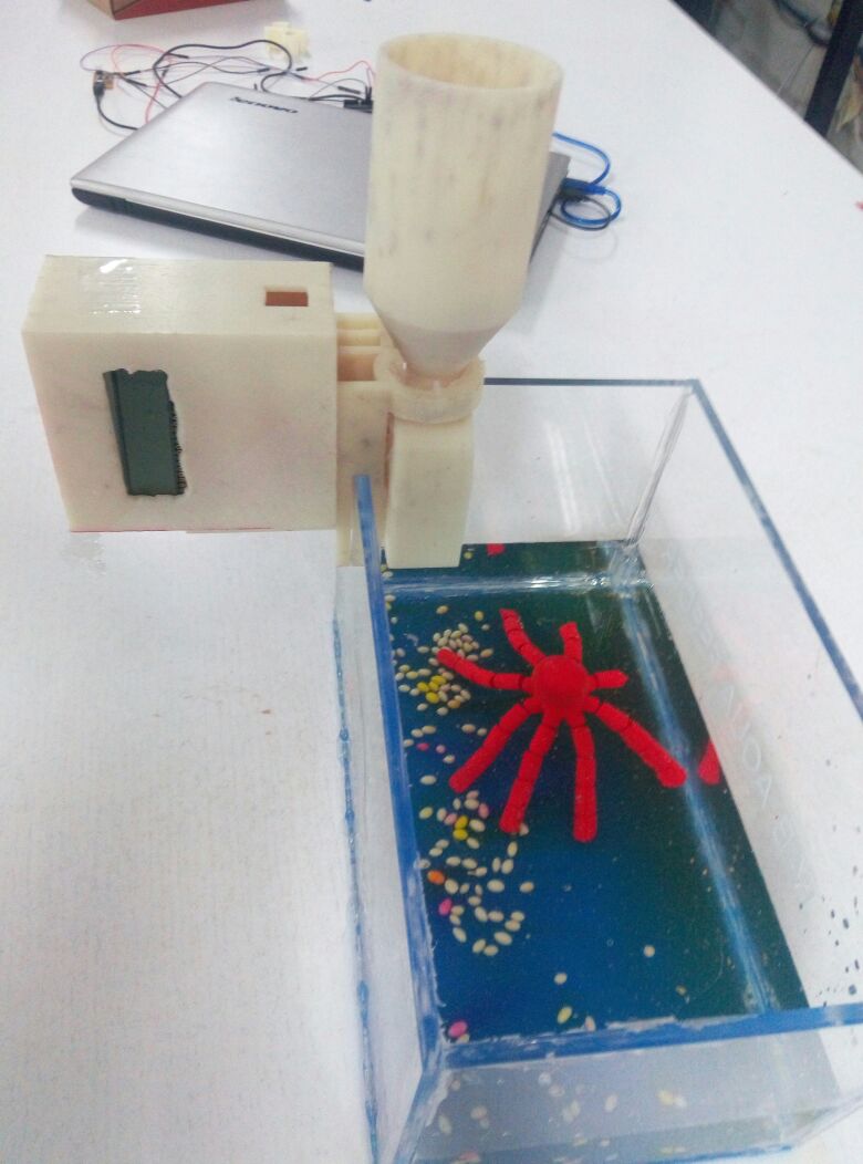
Now it was time for tesing.I filled the tank with water and filled food container with some fish feed.There was some problem with the power supply connection so instead i used my laptop to power the boards.
Tasks to be completed/Upgradation-
Time has run out for me. Only a day remain till the end of fabacademy.However i plan to keep working on the product and correct the mistakes and add the planned upgradation.
- Add PH sensor
- Add Temperature sensor
- Redesign the display board using atmega-328p IC and a Real time clock
- Implment the interface
- Add a LED light system
Bill of Materials
Body- 6mm Acrylic clear 2 sheets 1ftx2ft(Fablab).
- Plywood(Laser Cutter) small piece
- ABS Plastic(3D printing)
- PCB FR1 large × 1
- satshakit board components cost- 150₹ (BOM available in the sathshakit download link )
- servo motor(from fablab inventory
- Attiny44 microcontroller
- LCD Display
- 5v 1A voltage regulator
- 20MHZ resonator
- Resistors-10k,100k
- capacitor-10 uf
- 2x3 Pin Header
- 2x2 Pin Header x 3
- 2x5 Pin Header
- 1x17 Pin Header
- 1x6 Pin Header(for FTDI cable)
- connector cables-M-M,M-F,F-F
What i learned- I learned a wide variety of information during my fab course. Previously i knew nothing about moldin&casting, Embedded electronics, mqchine design etc. During this course, i got a basic knowledge of all these. In Essence, i can confidently say i learned how to design,implement and build a project entirely on my own. Download Files-
- 3d printing files:
- Feeding mechanism 3ds max file
- Feeding mechanism STL file
- Mount design solidworks file
- Board Designs:
- Sathshakit Board
- LCD Board
- Regulator borad
- Laser Cutting:
- Aquarium
- Code:
- Motor program
- time program
Project Video