Week - 11
Input Devices(APRIL 13)
The assignment for this week is make some input devices to measure something: add a sensor to a microcontroller board that you've designed and read it. An input device provides information about a work environment such as magnetic fields, temperature, light, sound, acceleration, orientation, vibration and more ,this information is sensed by a device called sensor and then is processed and measured by a microcontroller.There are hello world example circuits to measure magnetic fields, temperature, light, sound, acceleration, orientation, vibration and more. I chose to build a temperature sensor ,Variations of this circuit can be used to measure temperature,a thermistor is a resistor whose resistance is very sensitive to temperature. Thus you can read the temperature by converting the electrical reading through the resistor times some coefficient of resistance.
First decided to desin Neil's thermistor board using Eagle software.here is some pictures during designing
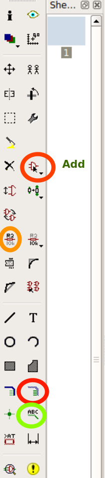
step-to add components
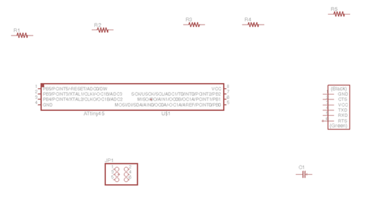
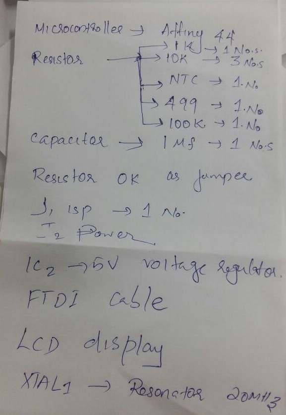
step-selected components,microcontroller,Jummper.
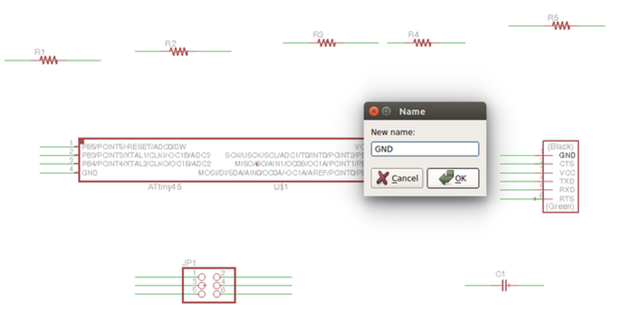
step-Naming selected components
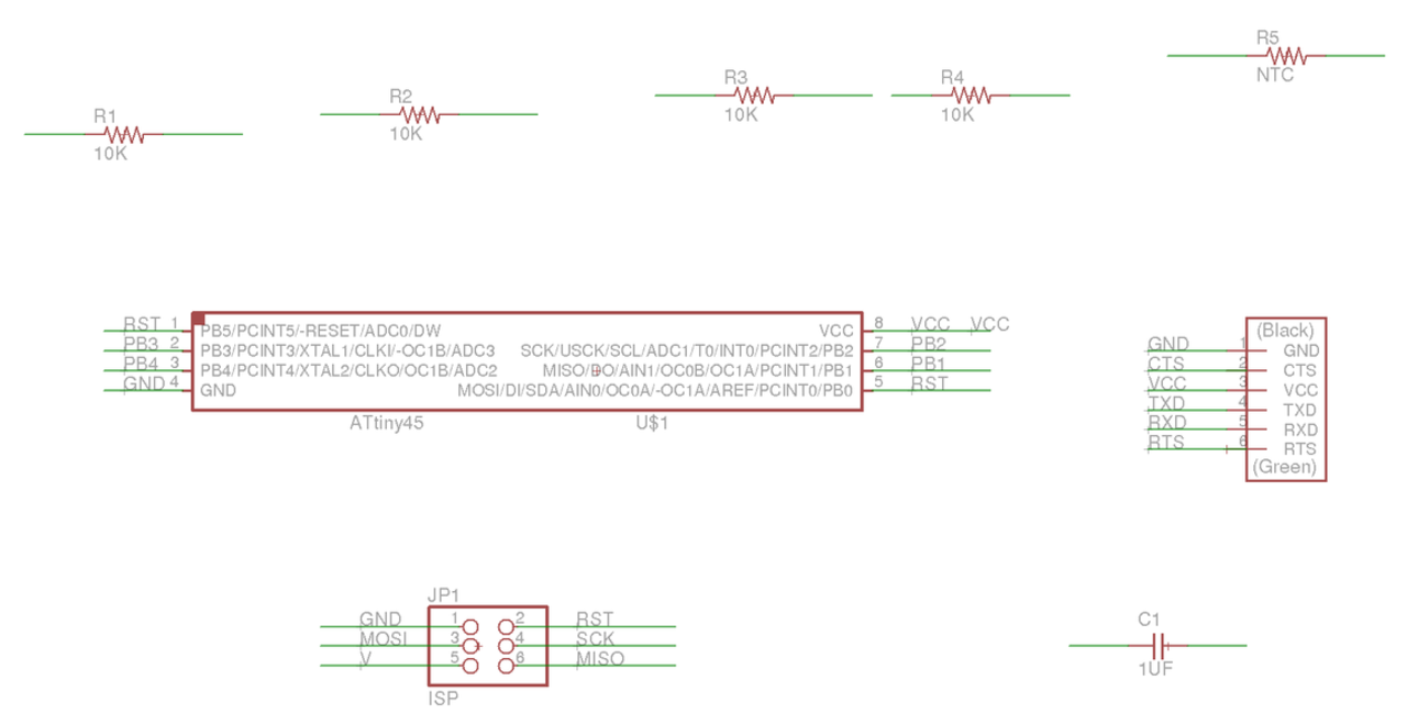
 Schemeatic in eagle-Neil's themistor board
Unfinished eagle design Designing board in Eagle was so boaring and time consuming,so i decided to switch in to kokopelli downloaded Niel's Thermistor board .
My own design
As it was so boaring and time consuming dropped "designing in eagle" idea...now i have got another idea to design Board which can sense the temperature and desplay the value in lcd simultaniously,An idea to combine two weeks,Input week and Output week-One single board (Attiny 44 microcontroller using)for both Input and Output
->As input portion i can desplay measuring temperature in a serial moniter
->As output portion display the measuring temperature using a LCD
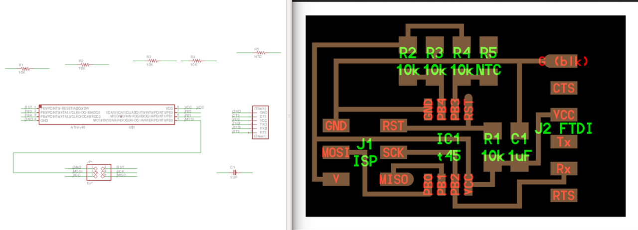
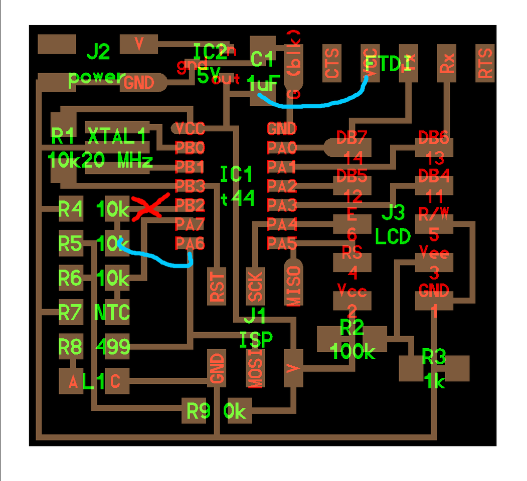
Redesigned the board to Thermistor plus display
Resigned Niel's board in Kokopellito desplay the measured temperature,for that added wheatston bridge
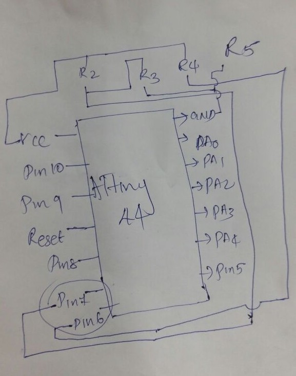
To design new board reffered Niel's LCD display board then added temperature sensing part of a thermistor(Wheatson bridge-as temperature increases ,resistance increses by measuring these resistance we can calculate the temprature,for that downlaoded NTC data sheet,
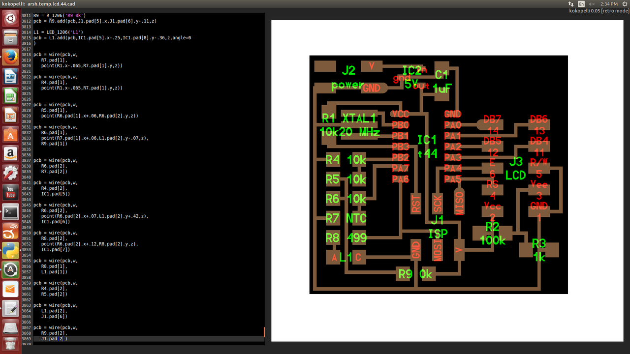
Design before adding FTDI
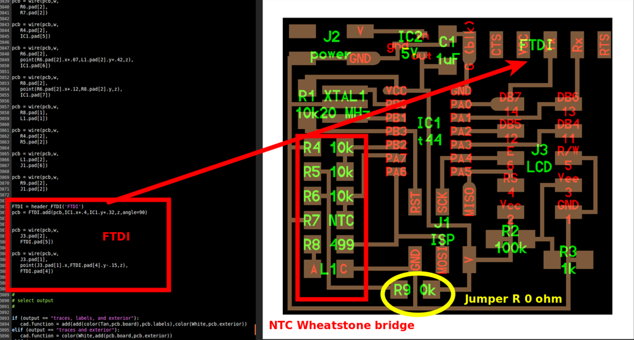
Design after adding wheatson bridge and FTDI
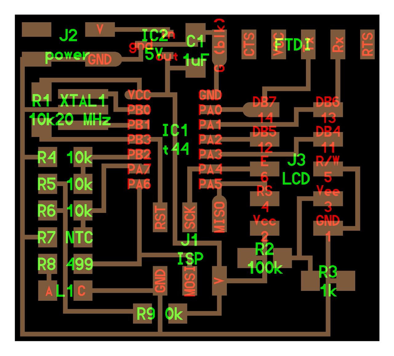
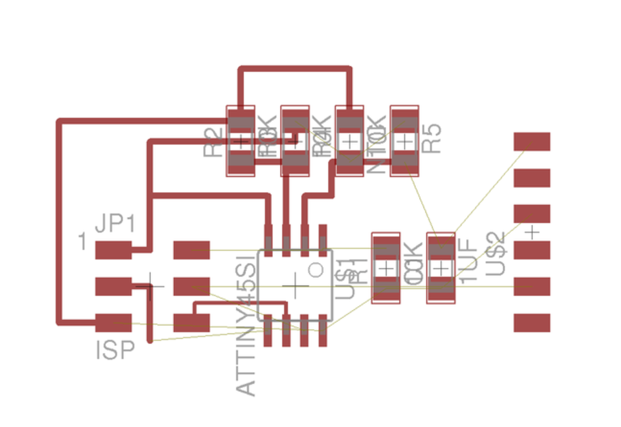
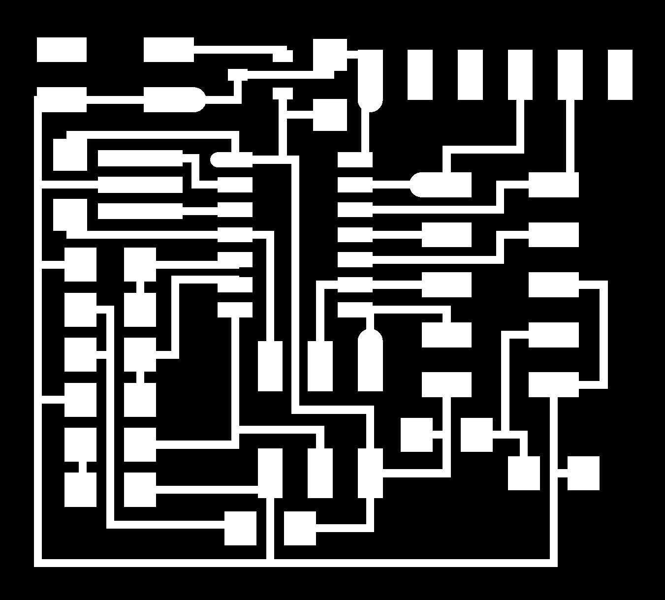
Final Design
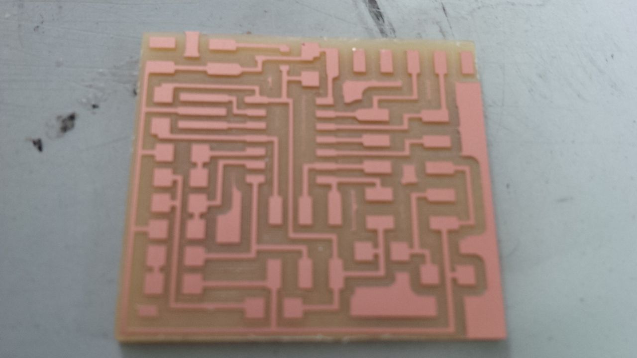
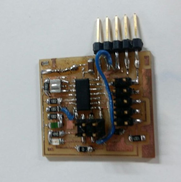
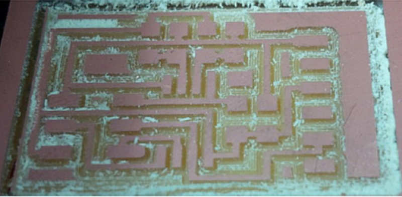
Final pcb after milling,now i have to stuff this board with components.
Problems occured:-
1.On Close Inspection found out a big mistake in board forgot to use PA6 and used PB2 instead,to fix this problem used jumper from PA6 to resistor 5 ,then disconnected PB2
2.IC2 started to overheat during programming ,first i assumed board is using more than 100 milliampere,but truth was another one.Board overheating was due to back current and started bouncing,to prevent the back current,i have got two options,one is remove IC 2 ,second one is remove 0ohm resistor at FAB isp board,so that i can prevent the back curent flow to the board,out of these two options i selected second option as it is best solution because i need IC2 (5v) as voltage regulator.
3.Forgot to connect FTD VCC with Attiny 44 VCCpin (i need this connection if i give power to board using FTDI Cable),solved this problem too.
programming the board:-
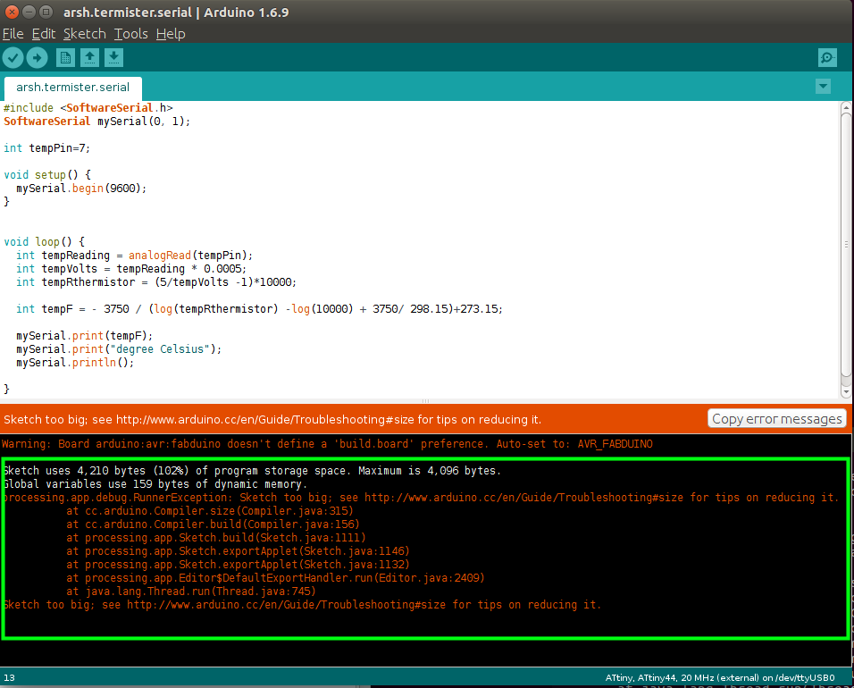
After fixing the problems,i tried to program again using following code
NTC (negative temperature coefficient) thermistors change their effective resistance over temperature. The most common equation used to model this change is the Steinhart-Hart equation. It uses three coefficients to characterize the NTC material with great accuracy.
The Steinhart–Hart equation is a model of the resistance of a semiconductor at different temperatures. The equation is:
1T=A+Bln(R)+C(ln(R))3
where:T is the temperature (in kelvins) R is the resistance at T(in ohms)
A, B, and C are the Steinhart–Hart coefficients which vary depending on the type and model of thermistor and the temperature range of interest.
V measured = tempReading (5/1024) tempRthermistor = (5/tempVolts -1)1000;tempT0 = 273+25 tempB = 3750 temp R0 = 10000 tempF = - tempB / (log(tempRthermistor) -log(tempR0) + tempB/ tempT0)+273.15;
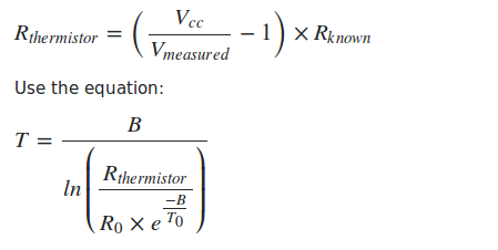
Use it as one leg (say the "upper" leg) in a voltage divider circuit with the other leg being a known resistance. Measure the voltage at the midpoint of the divider (e.g. with an analog-to-digital converter). Infer the thermistor resistance from the measured voltage as:
 #include <SoftwareSerial.h>
SoftwareSerial mySerial(0, 1);

int tempPin=7;

void setup() {
  mySerial.begin(9600);
}


void loop() {
  int tempReading = analogRead(tempPin);
  int tempVolts = tempReading * 0.0005;
  int tempRthermistor = (5/tempVolts -1)*10000;

  int tempF = - 3750 / (log(tempRthermistor) -log(10000) + 3750/ 298.15)+273.15;

  mySerial.print(tempF);
  mySerial.print("degree Celsius");
  mySerial.println();

}But i didn't get the desired output
To run this attiny 44 memory is not enough,Attiny 44 microcontroller has only 4090 bytes,but my code needs 4210 bytes because i has loop instruction,so it loop memory ,that is 2 percentage extra,next my step was to minimize my code,but it didn't work because if i minimize program anymore,code won't work at all.
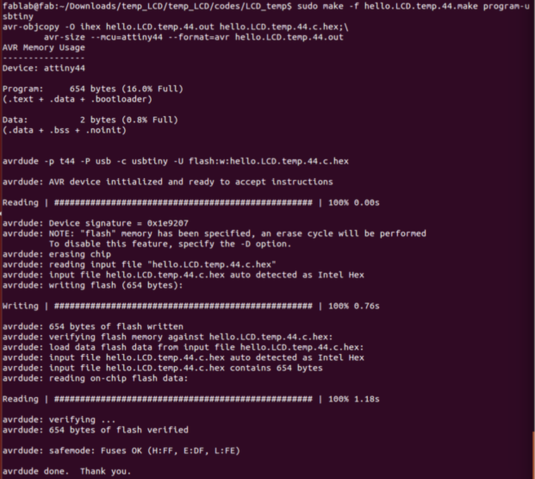
So i decided to use LCD which i have alreday implemented redisgned board to display emperature value as output,here the link
Niel's thermistor board
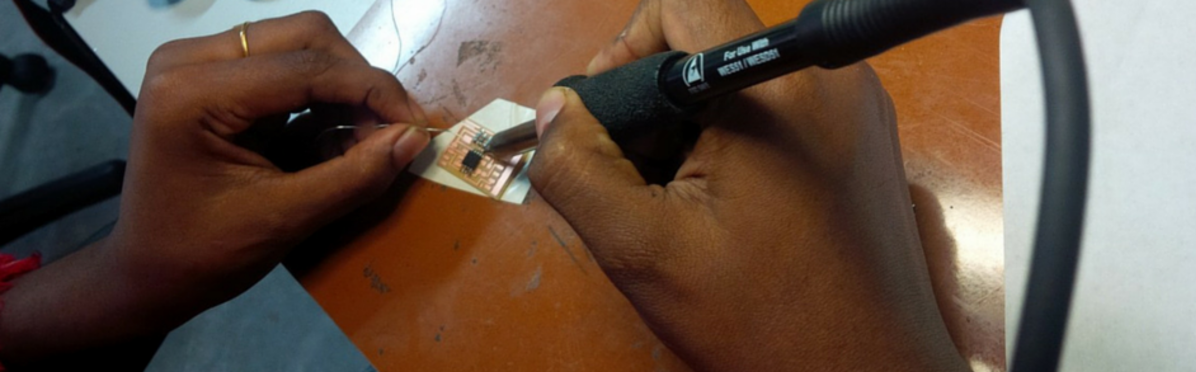
Milling and soldering board Neil's Board
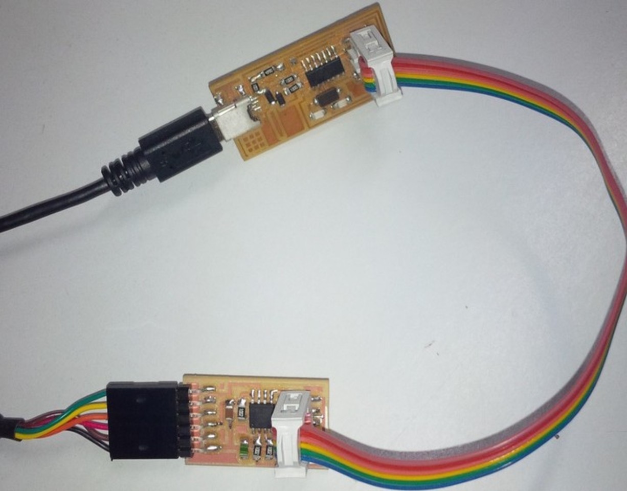
Programming Board
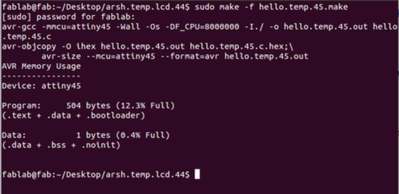
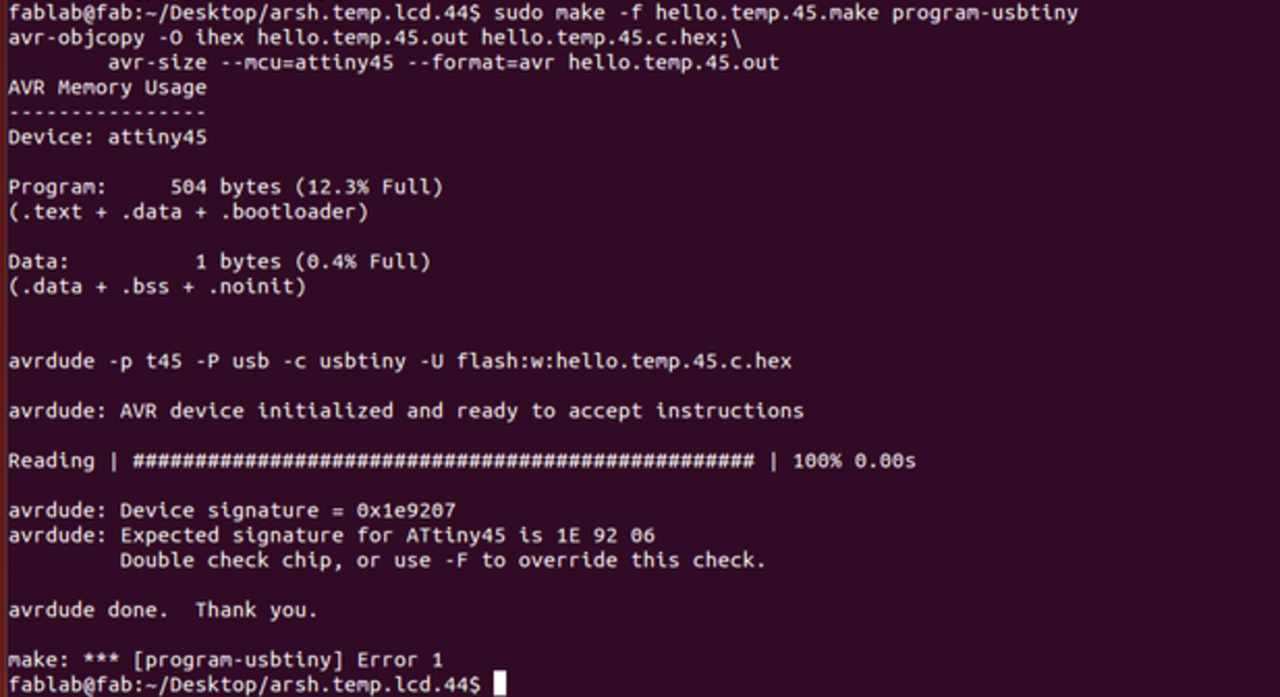
To program the board first i had to download hello.temp.45.c ,makefile, hello.temp.45.py,python,I used fabISP to program the board.Connect the board and fabISP together and also with computer.For compiling program to hex use the following code:
sudo make -f hello.temp.45.make
Command to program the board
sudo make -f hello.temp.45.make program-usbtiny
Output verification
Files
Arsh.Thermistor.LCD.44