Week - 9+10 Mechanical design (Mar 30) and Machine design (Apr 6)
Assignment
- make a machine, including the end effector build the passive parts and operate it manually, document the group project and your individual contribution
- automate your machine, document the group project and your individual contribution
Scrapbot- Automated Dust Collector(Made using scrap materials)
Team
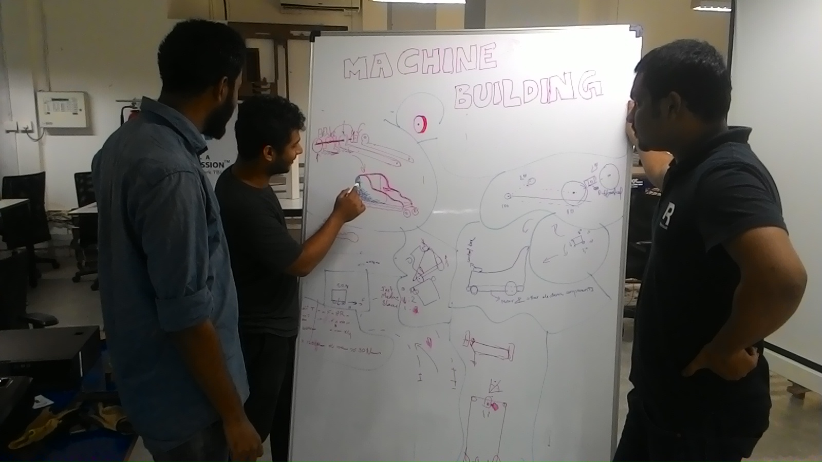
For our machine building group project, we decided to build a mini version of an electric wheelchair which could be used by handicapped children, specifically for children with no legs.The sitting platform will be only be slightly above ground, thus making it easy for handicapped people to get on it. Halfway through the project, since we couldnt get access to the required motor, we decided to change the project to Automatic cleaning machine.The entire machine would be built using scrap materials so as to minimize the cost.
This final output.
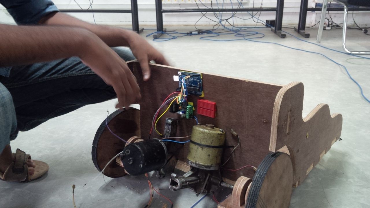
Here is the vedio how it works
MY CONTRIBUTION-ELECTRONIC PARTS
My contribution to this project is selection of electronic components,electronic parts assembling,so first i googled about projects related to this project idea.I got an awsome thing that is fabduino,sofirst i decided to make a fabduino. Tried to make Fabduino,Fabkit i/o (aka Fabduino) is a Fabable Arduino Compatible Board.I was soo excited to make a fabduino for the first time. First I dawnloded the FABDUINO files from http://fabacademy.org/archives/2015/doc/projects/fabkit-0.4.html
Here i am gonna mill version 4.
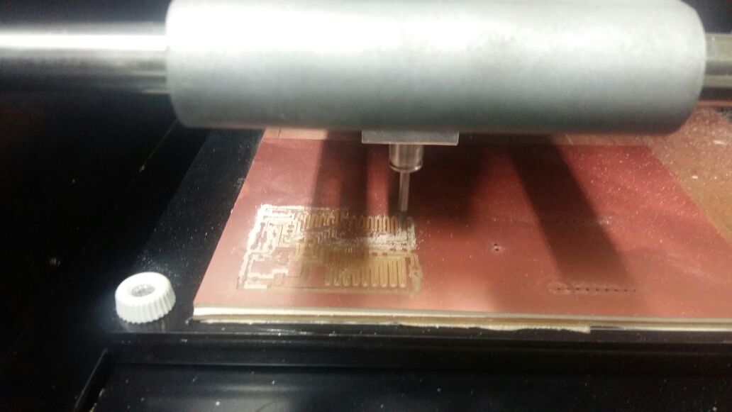
Milling

Fabduino pcb
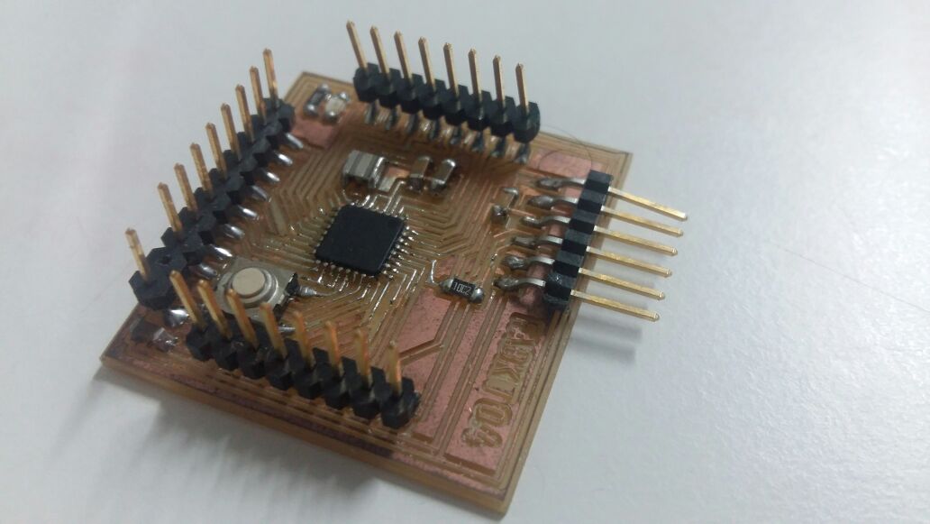
Fabduino finally soldered.
fabduno error pic,
Here we can't use Fabduino,so we decided to move on using Audino uno intsead of fabduino,because we don't have much time.
Circuit component:-
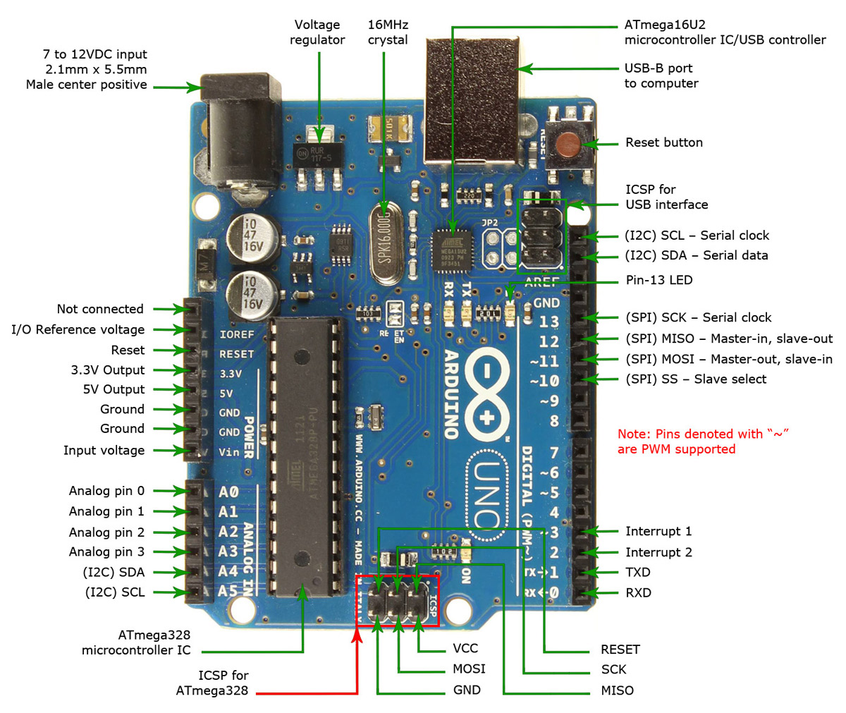
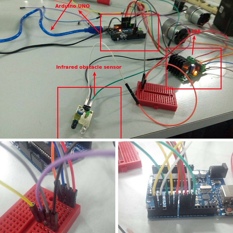
Arduino UNO
First off we bought an Arduino UNO from nearby electronics shop,Arduino Uno is a microcontroller board based on the ATmega328P, It has 14 digital input/output pins (of which 6 can be used as PWM outputs), 6 analog inputs, a 16 MHz quartz crystal, a USB connection, a power jack, an ICSP header and a reset button. It contains everything needed to support the microcontroller; simply connect it to a computer with a USB cable or power it with a AC-to-DC adapter or battery to get started.This project need more memory because we are going to use loop functions,and Arduino uno has sufficient pins for this project ans this is same as fabduino 4,so we decided to use this.
Pin configuration
Arduino uno
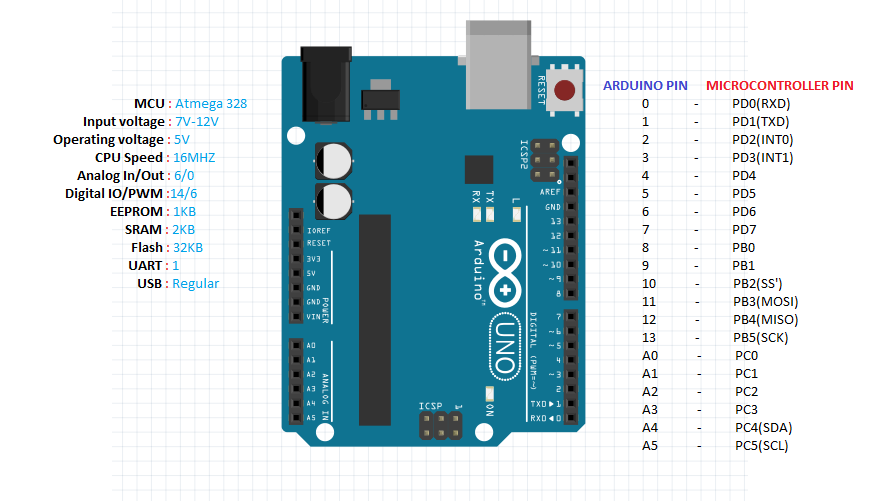
Arduino pin
Infrared obstacle sensor -2 .No.s
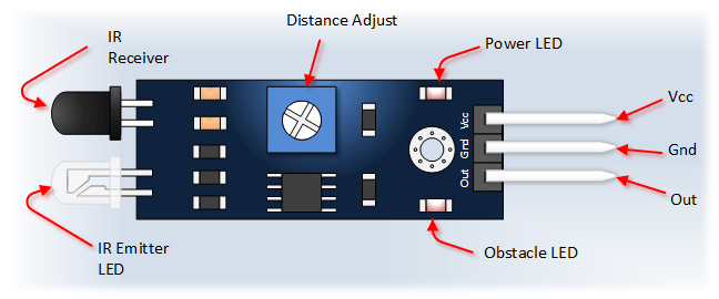
Function:-
In this project DIY Scrapbot is automatic stearing,so i have to detect obstacle in both sides ,for that i decided to use IR sensor .
- HC -SR04 Ultrasonic sensor- 1 No.
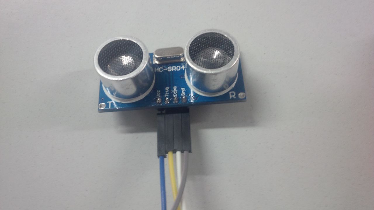 Function in this project:
this diy scrapbot is automatic stearing,so i have to detect obstacle infront ,for that i decided to use IR sensor
Function in this project:
this diy scrapbot is automatic stearing,so i have to detect obstacle infront ,for that i decided to use IR sensor
- L298 Motor
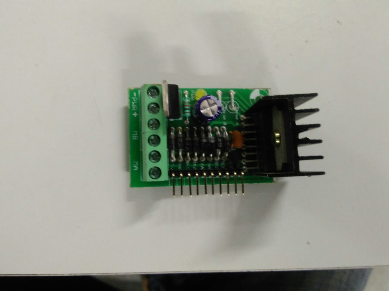
L298 description is motor driver to control motor speed and power output ,this motor is using to drive the motor and controll the motor.controlling means forward direction and backward direction,we giving stearing to scrapbot using this motor(using 2 no.s) .working method is at a time one motor will be in on mode and another one will be in off mode or in reverse direction mode,using this method we caan create turning in any direction.so L298 is more accurate for this purpose.
L298 can work till 12V input ,there is a relay action inside L298, power providing directly to l298 from battery,l298(regulated 5v) and this will directly conncted to arduino,using breadboard and also each and evry sensors are connected to arduino ,this aurduino is also provided power(5v) and ground.
int trigPin = 2;
 int echoPin = 3;
 long duration, cm, inches;
 // motor one
 int enA = 10;
 int in1 = 5;
 int in2 = 4;
 //digitalWrite(enA,HIGH);
 // motor two
 int enB = 9;
 int in3 = 7;
 int in4 = 6;
 //digitalWrite(enB,HIGH);
 //IR Obstacle sensor
 int LED = 13; // Use the onboard Uno LED
 int inputpinleft = 11; //input pin from left IR sensor
 int inputpinright = 12;//input pin from right IR sensor
 int val = LOW;
 int val1 = LOW;
 int val2 = LOW;
 int a = 0, b = 0, c = 0;

void setup()
{
  Serial.begin (9600);
  pinMode(trigPin, OUTPUT);//set ultrasonic sensor triggerpin as input
  pinMode(echoPin, INPUT);//set ultrasonic sensor echopin as output

  // set all the motor control pins to outputs
  pinMode(enA, OUTPUT);
  pinMode(enB, OUTPUT);
  pinMode(in1, OUTPUT);
  pinMode(in2, OUTPUT);
  pinMode(in3, OUTPUT);
  pinMode(in4, OUTPUT);
  pinMode(LED, OUTPUT) ;// define LED as output interface
  pinMode(inputpinleft, INPUT) ;// define the obstacle avoidance sensor output interface
  pinMode(inputpinright,INPUT) ;
}
int frontsensor()
{
  digitalWrite(trigPin, LOW);
  delayMicroseconds(5);
  digitalWrite(trigPin, HIGH);
  delayMicroseconds(10);
  digitalWrite(trigPin, LOW);
  pinMode(echoPin, INPUT);
  val = digitalRead (echoPin) ;
  duration = pulseIn(echoPin, HIGH);
  cm = (duration/2) / 29.1;
  inches = (duration/2) / 74;
  if(cm<=30)
  {
  Serial.print(cm);
  Serial.print("cm");
  }
  Serial.println();
  delay(1000);
  return cm;
}
bool leftsensor()
{
  val1 = digitalRead (inputpinleft) ;
  return val1;
}
bool rightsensor()
{
  val2 = digitalRead (inputpinright) ;
  return val2;
}

void loop()
{
  frontsensor();
  while( cm >= 30)//when there are no obstacles within 30cm
  {

      Serial.print(cm);
      Serial.print("cm");

    Serial.println();
    digitalWrite (LED, HIGH);
    // turn on motor A
    digitalWrite(in1, HIGH);
    digitalWrite(in2, LOW);
    // set speed to 200 out of possible range 0~255
    analogWrite(enA, 200);

    // turn on motor B
    digitalWrite(in3, HIGH);
    digitalWrite(in4, LOW);
    // set speed to 200 out of possible range 0~255
    analogWrite(enB, 200);

   if(cm<30)
    break;
   frontsensor();
  }
  //if any obstacles detected within 30cm
  //motor A & B OFF
  digitalWrite(in1, LOW);
  digitalWrite(in2, LOW);
  digitalWrite(in3, LOW);
  digitalWrite(in4, LOW);
  delay(2000);//delay to check both IR sensors
  rightsensor();
  leftsensor();
  if((val1 == LOW)&&(val2 == LOW))//if both left and right are clear
  {//motor A ON
   digitalWrite(in1, HIGH);
   digitalWrite(in2, LOW);
   analogWrite(enA, 250);
   //motor B OFF
   digitalWrite(in3, LOW);
   digitalWrite(in4, LOW);
   delay(3000);
   //turn right
  }
  if((val1 == HIGH)&&(val2 == LOW))//obstacle detected by left sensor
  {//motor A ON
   digitalWrite(in1, HIGH);
   digitalWrite(in2, LOW);
   analogWrite(enA, 250);
   //motor B OFF
   digitalWrite(in3, LOW);
   digitalWrite(in4, LOW);
   delay(3000);
   //turn right
  }
  else if((val1 == LOW)&&(val2 == HIGH))////obstacle detected by right sensor
  { //motor A OFF
    digitalWrite(in1, LOW);
    digitalWrite(in2, LOW);
    //motor B ON
    digitalWrite(in3, HIGH);
    digitalWrite(in4, LOW);
    analogWrite(enB, 250);
    delay(3000);
    //turn left
  }
  else //obstacles on both left and right
  {
    digitalWrite(in1, LOW);
    digitalWrite(in2, HIGH);
    //analogWrite(enA, 400);
    digitalWrite(in3, LOW);
    digitalWrite(in4, HIGH);
    //analogWrite(enB, 400);
    delay(3000);
    //reverse
  }
}
Programming part was Nizam and me,to code me and nizam discussed about control inputs,sensor control inputs,pin configuration.
Ultrsonic sensor pins-Trigger pin 2 and echo pin 3
Motor 1-pins 10,5,4 Motor 2-pins 9,7,6
I R Left -pin 11 I R right-pin 12
Program evaluation calibration.
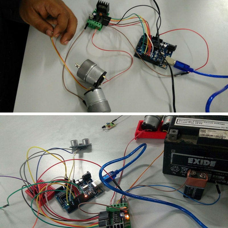
Before fittiing wiper motor we tested the program and electronics working using dc motor,we tested and evaluated programm. next is programm calibration,for that we manually blocked all sensors using hand then checked wether end effecter's output is same as we planned.Yaheee..its okai..almost done..now my contribution is almost sucess,now i have to help them with other works.