Electronic Design
Assignment:
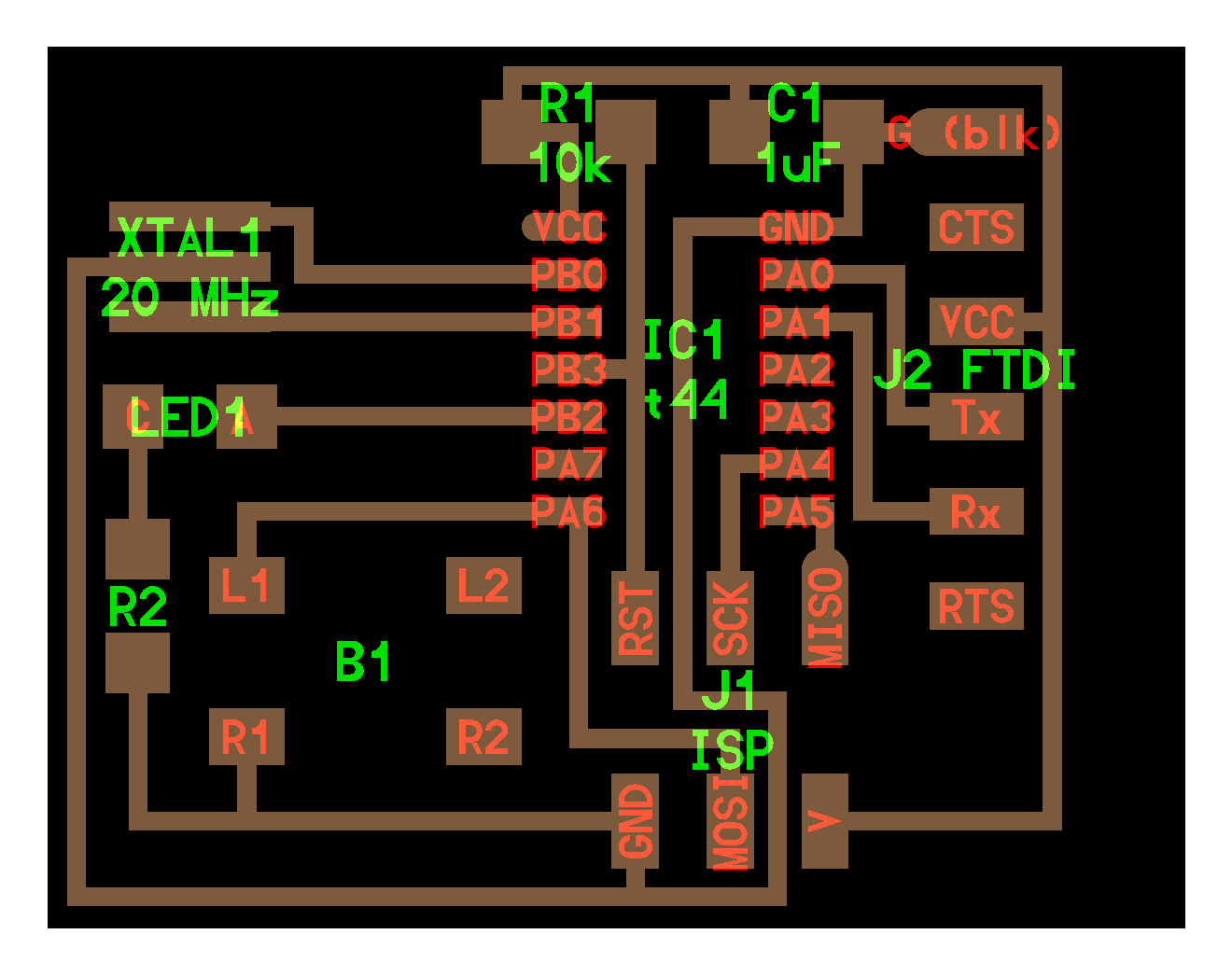
1.redraw the echo hello-world board , and add (at least) a button and LED (with current-limiting resistor) 2.check the design rules, and make it 3.mill the board using Modela and solder the components on to it. The board was designed as so: (not to scale)
softwares I am familiar to design PCB board:Kokopelli,Eagle,123D circuits, ZenitPCB
For this week i decided to go on with Kokopelli,as it take less time thn softwares like Eagle(Thats what i felt)
Kokopelli Installation
Kokopelli is a software tool for computer-aided design and manufacturing,an opensource tool the design the PCBs,2D and 3D models can described as Python scripts
I am new to Kokopelli and starting out right in the kokopelli for UBUNTU version 14.04.first of all i downloaded KOKO-RETRO ZIP from the link -exctracted it open the folder koko-retro
Open Terminal-Use the following instruction
make cleancd binmake fabmake install
to open kokopelli
./kokopelli -r
the code was to draw a circle, but there were no circle as output,Error occured- No output
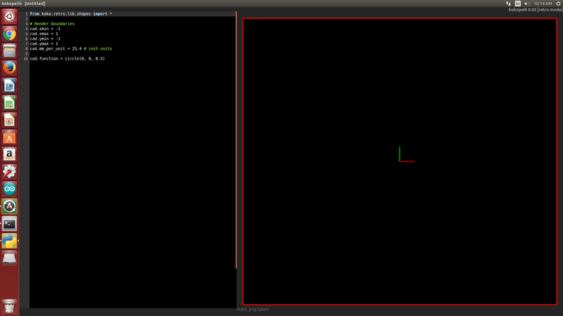
Terminal.........
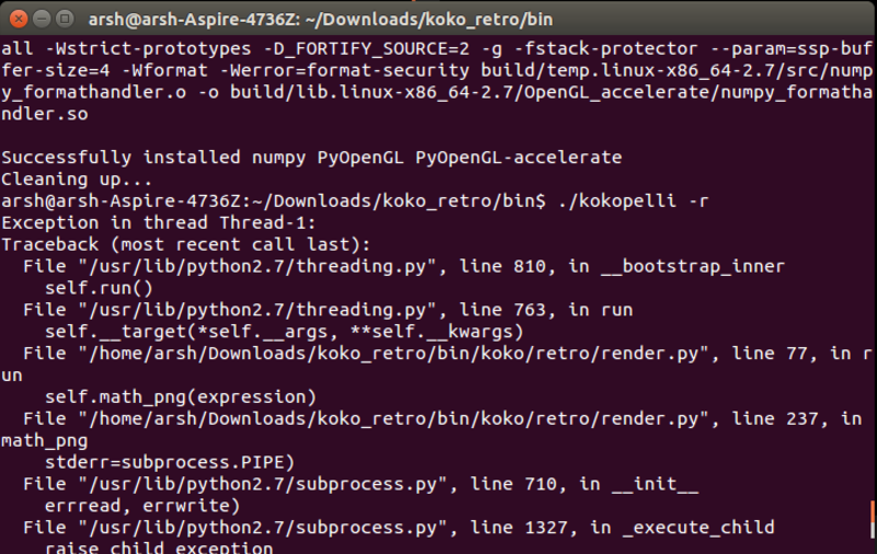
Solution
Refered -"github-mkeeter /kokopelli/wiki/installing",now i got the solution,that is,We should install some python libraries already in pc to run Kokopelli
and i got the required Python libraries are available through pip.
sudo pip install numpy PyOpenGL PyOpenGL_accelerate
Again i tried to open Kokopelli
open terminal
use the command 'sudo ./kokpelli -r
OopS.....Still no oputput....
To troubleshoot-referred http://kokompe.cba.mit.edu/-Downloads
I hope i can solve this problem by using following commands
make install -this one will copy all executables and scripts to /usr/local/bin.
Alternatively, you can add the bin folder to your path. To do this, add the line `
export PATH=fab/bin:$PATH
to ~/.bashrc, with fab/bin replaced by the location of the bin directory.
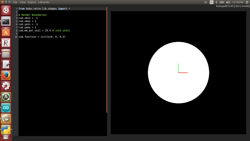
Finally it worked!!!!............i got the desired output...
The very next step which i have donewas downloading the ".cad" file from the link
http://academy.cba.mit.edu/classes/embedded_programming/index.html
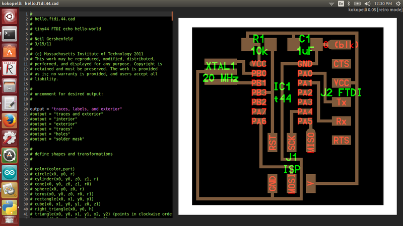
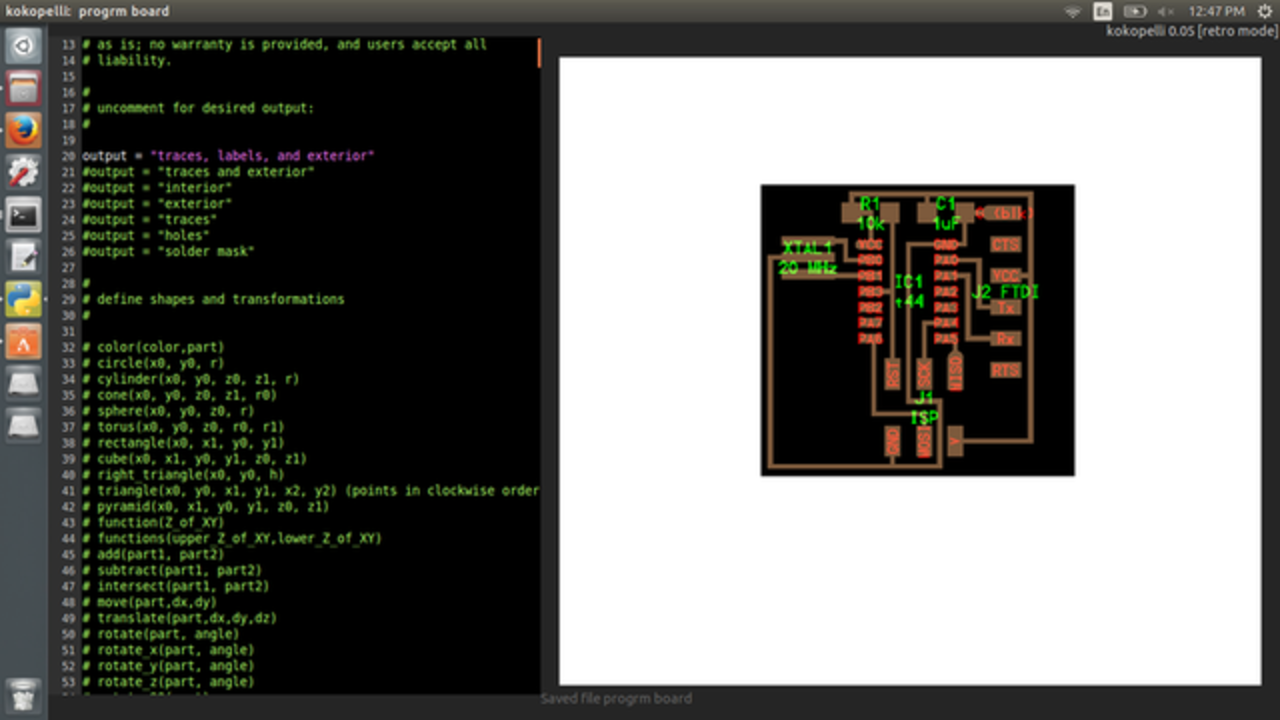
-opened the downloaded ".cad" file in Kokopelli, File->Open->hello.ftdi.44.cad
its format was quiet intresting,which display an ordered list in two columns, left side for the code, and right side the pcb preview.
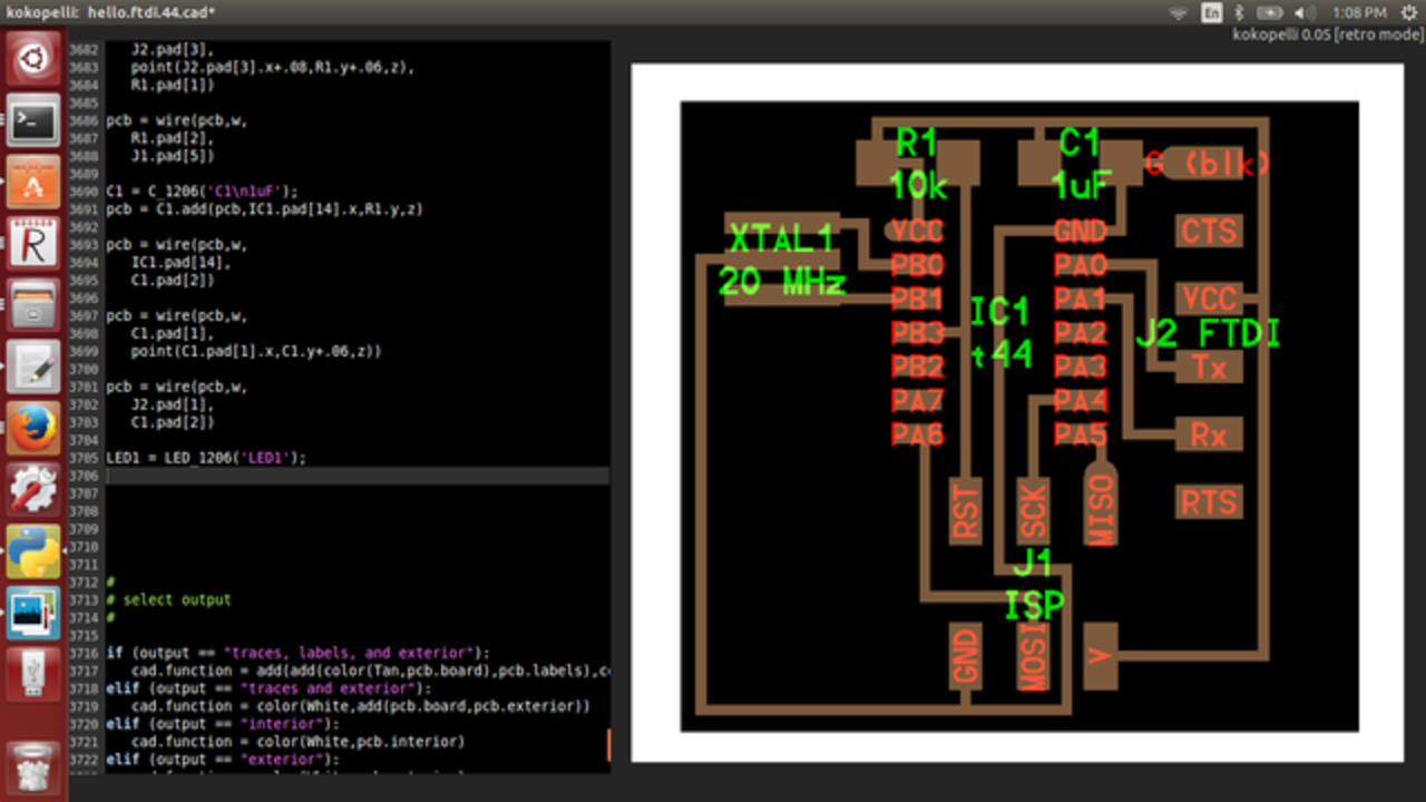
Using fuctions in kokopelli to add a component which we need,wire the component and allign the pcb,step by step tutorial to do add a component.
Tutorial link
downloaded the CAD file ,here is the link
Used gedit to open the cad file then find out the resistor,LED ,Button,copied it and edited the code in KoKopelli
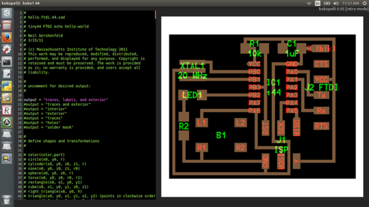
Niel's Board in Kokopelli
Reffered Niel's tutorial to design the board
changed the code on the left terminal then got corresponding change in circuit diagram on right terminal
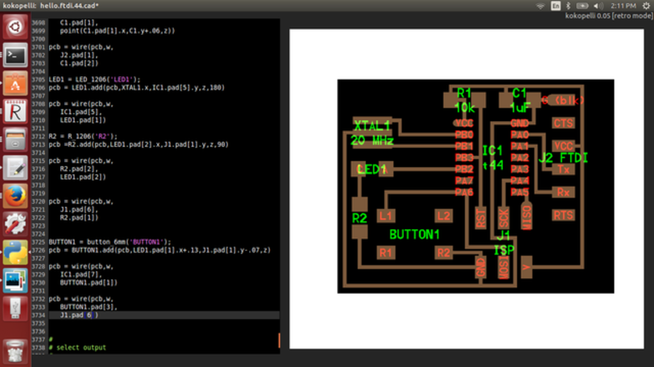
Board after adding components
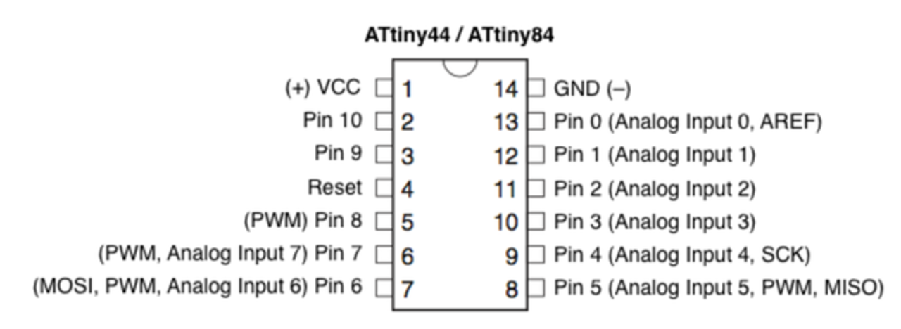
To give the correct pin positions i reffered attiny44 data sheetInput Devices
 Input Devices
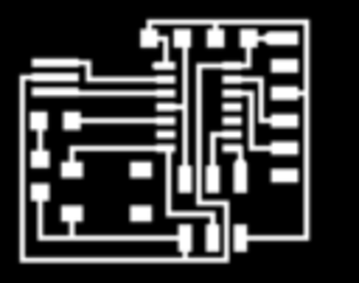
now the board designing part has got completed ,next step is to upload the file as png file, for that edited 20th and 21st line(delete#),then export as png.To mill the board we should upload the file as png. here is the traces that going to upload to mill
next step was milling,The files were then taken to the Modela and the design file was opened using FabModule. Well, it might be a little amateurish, but I've done it. I made some changes today that messed it up, so I learnt a lot fixing it.
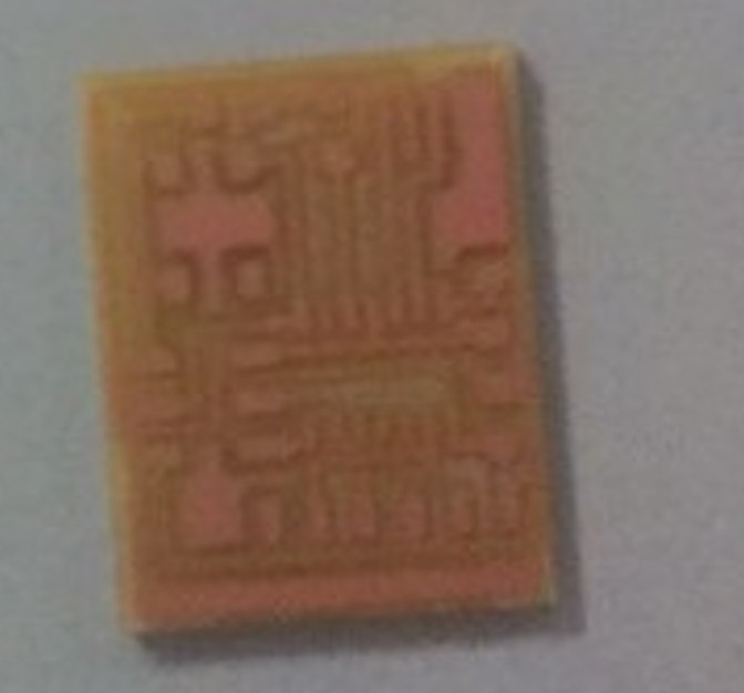
Here is my board after milling
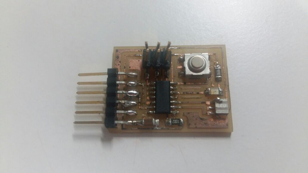
soldering hello ftdi board:-
Soldering part was quiet easy,as i have got experiance in soldering.One mistake i made during soldering was ,placed LED instead of resister,used the heat gun,desoldered it and made it ok.
Added a LED,RESISTOR AND BUTTON in using KOKOPELLI