| Home | | Weekly Assignments | | Final Project | | Photo Gallery |

Week 4: Electronics Production
This week of Fab Academy teaches how electronics production. As a first step towards learning electronics production, I'll be creating an electronic board using Modella mini CNC mill we have in Kochi FabLab

Roland Modella MDX-20 is a desktop 3D plotter, a versatile machine capable of milling PCBs, carving moulds with soft materials like wax and also scanning 3D models of objects.
For this week's assignments, I am going to create a Fab ISP board using Roland modella. A FabISP is an in-system programmer which allows you to program microcontrollers on the boards we make at FabLab. The FabISP itself can be made in Fablab using Modella and electronics workbench
Board production using Roland Modella 3D plotter.
Here I am using FR-1 copper board to make FabISP using modella. The drill bits on modella grinds of the unwanted parts of the layer on the copper board to create beautiful PCBs.
Milling bits
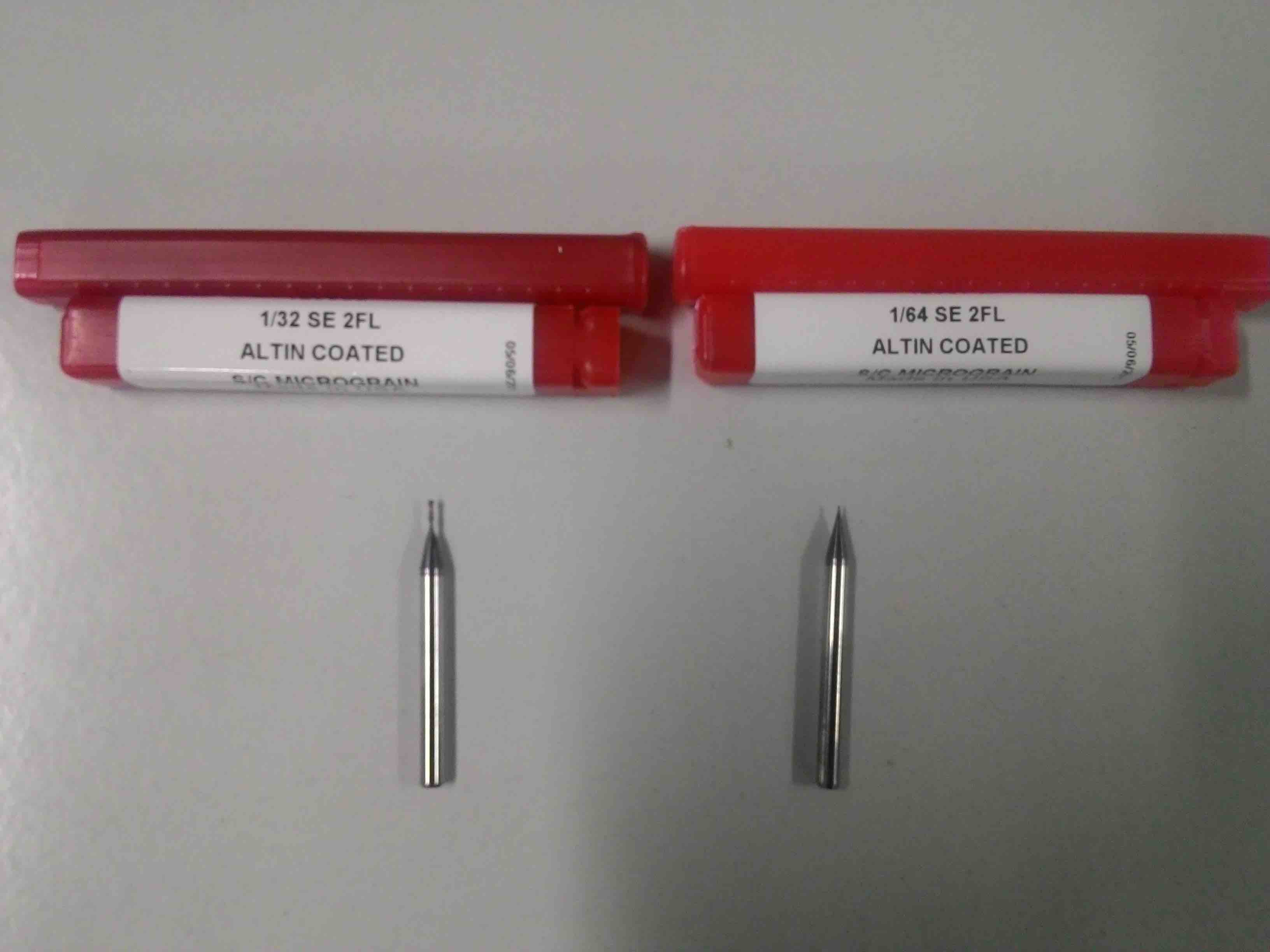
Milling bits are classifieds based on their diameter, ends and flutes. For creating FabISP, we would be using two drill bits.
1/64 in drilling bit is used to remove copper layer from board
1/32 in drilling bit is used to cut the board.
Things required in FabLab
For creating FabISP, we need the following things in FabLab
1. Roland Modella MDX 20
2. A computer running Ubuntu
3. FR-1 copper clad board
4. Double sided tape
To create the board, the board layout can be designed using EAGLE, a png file with white traces is exported and with the help of Fab Modules, the board is made on Modella.
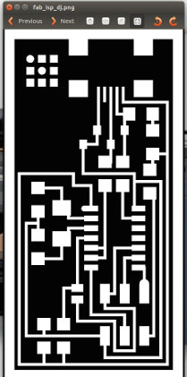
The board
PNG image is exported.
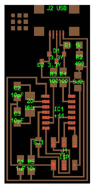
Notes
* Components marked with an "R" (R1, R2, etc) are resistors.
* Components marked with a "C" (C1, C2, etc) are capacitors.
* J2 USB is the mini USB header
* IC1 t44 is an attiny44a microcontroller. The little circle on the microcontroller that should be facing to the top left. This circle/dot can be viewed using a magnifying glass. If the microcontroller is placed upside down, the board will never work.
* The resistors and capacitors of this board do not have polarity.
Using Fab Modules for creating board
Fixing the right drill bit
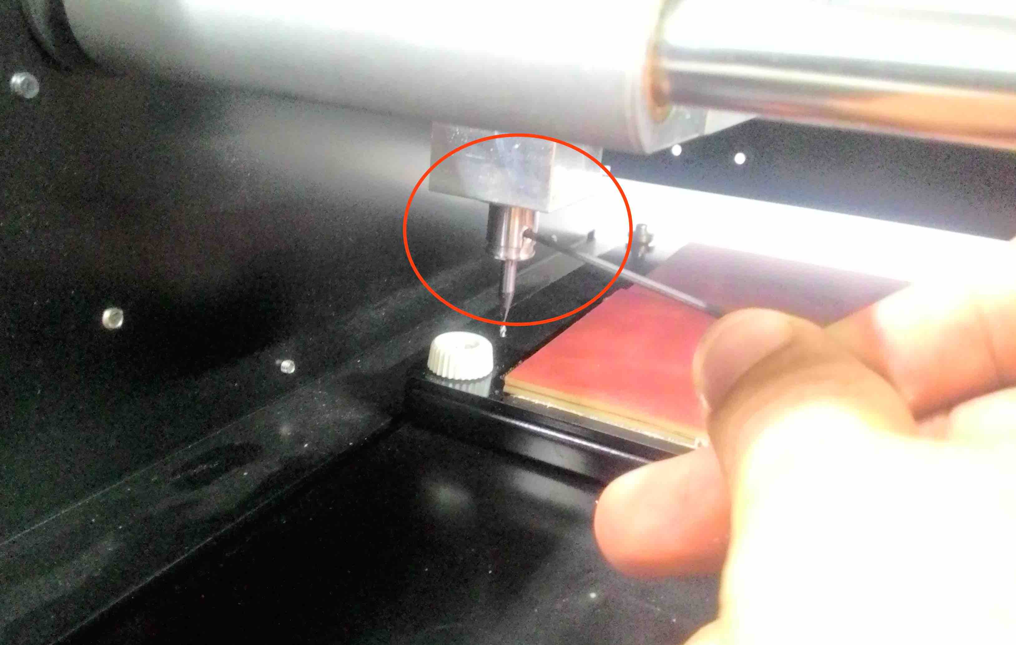
Drill bit can be replaced by loosening the the grip using allen key. Here I am fixing 1/64 inch bit to do the milling part and then the machine is swtiched on.
Setting up origin.
Origin can be set up by changing Xmin and Ymin values on the fab modules and clicking the move button.
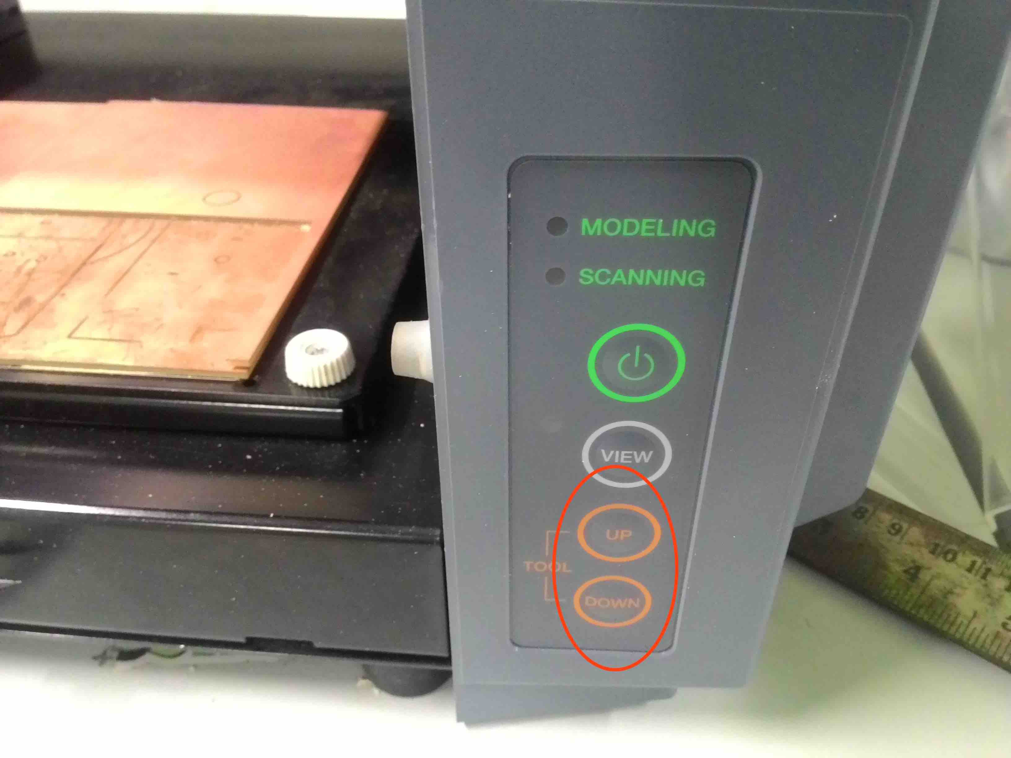
The z axis orgin can be setup by moving down the milling bit by clicking the physical move (UP/DOWN) key on the medella machine. The drilling bit can be loosened using allen key, allowed to drop on the board and once bit touches the surface of the board. The drilling bit should be tightned again after it touches the surface of the board.
Placing the board on the plate
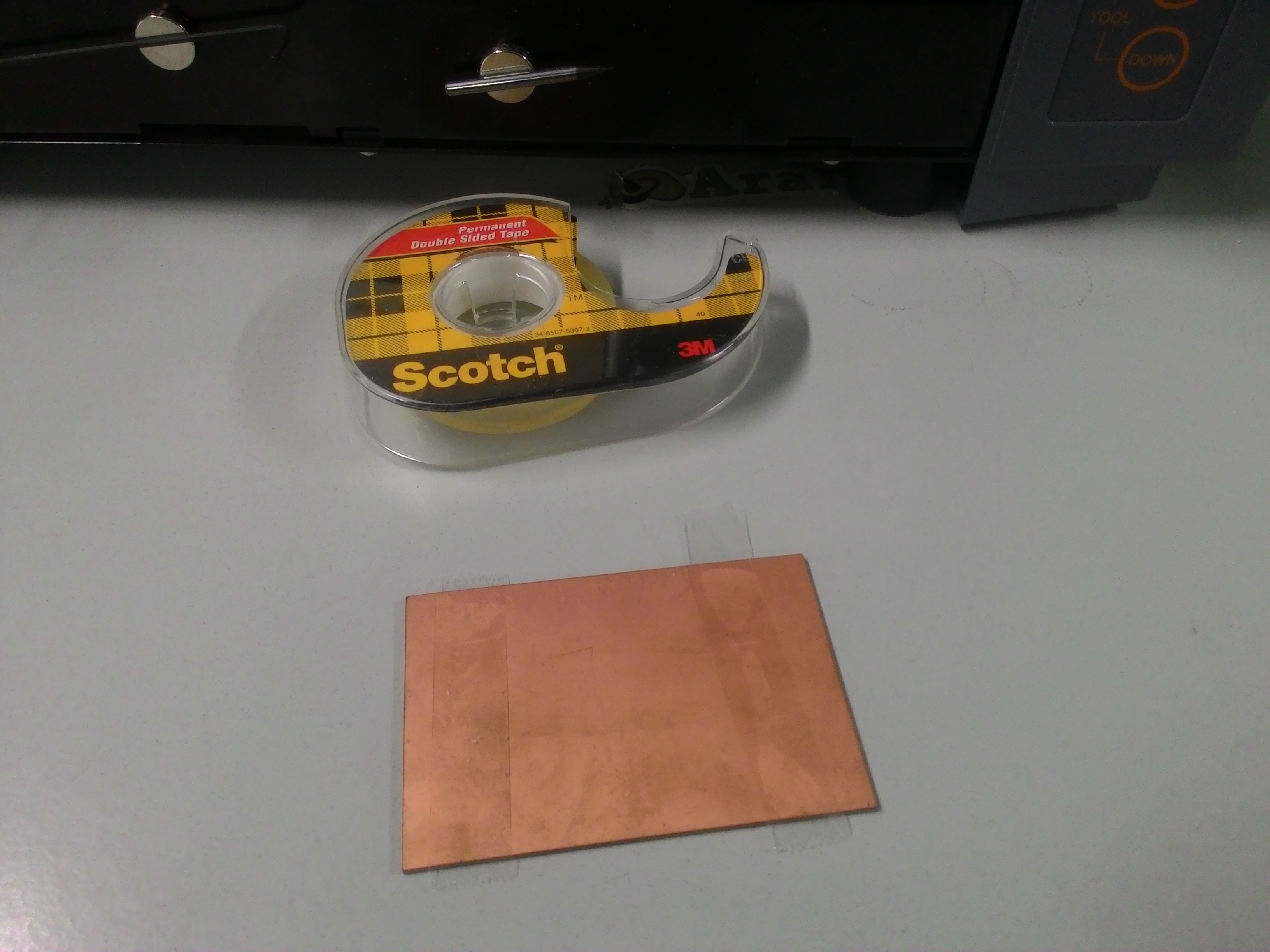
I used double sided tape to stick the rear surface of the board onto the bed. This will ensure that the board stays still while its being milled by the machine.
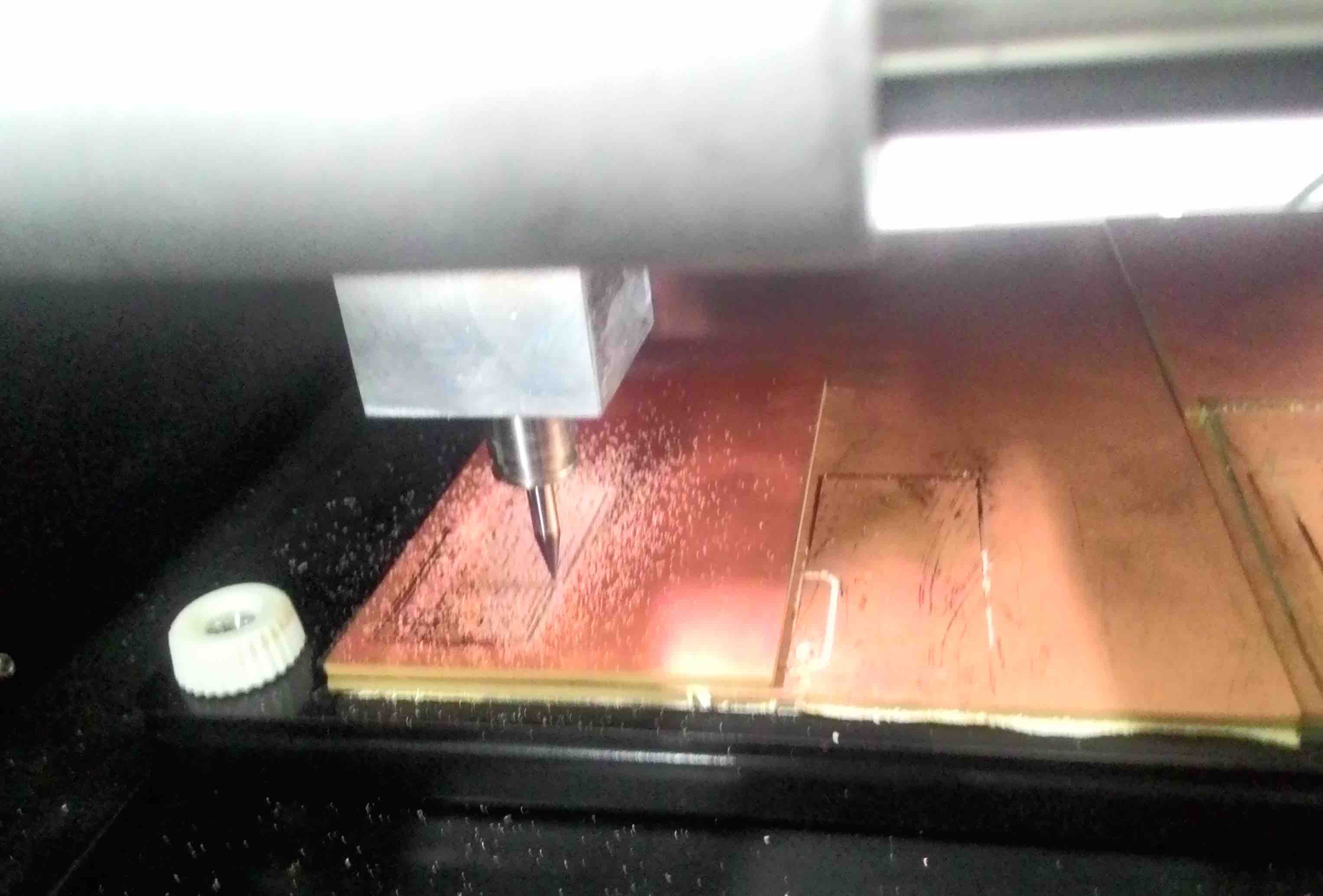
Milling the board
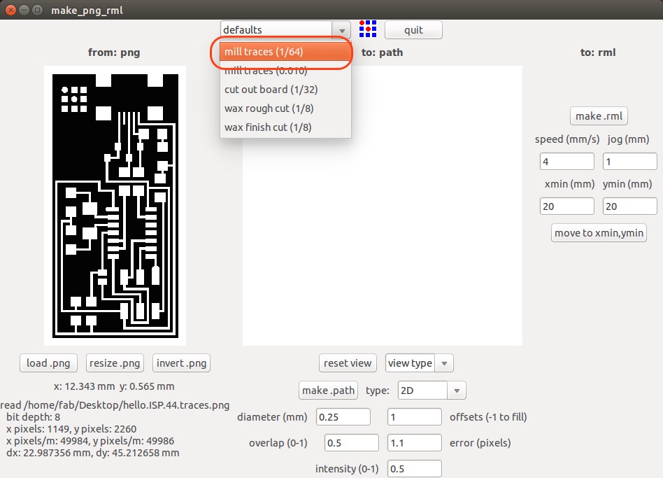
Once everything is setup, we need to click on "Make.rml" and the print order can be send to the machine by cliking "Send". The machine will right away start milling the board.
View button on the machine can be clicked to pause the operation and see the progress.
Cutting the board
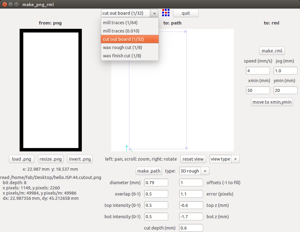
To cut the board from the main baord, the drilling bit should be replace with allen key to 1/32 inch, load the cutting PNG which has only the boundary of the board as its trace and repeat the same procedure. On the Fab Modules, we should also change the option to "cutout board(1/32) from the dropdown option.
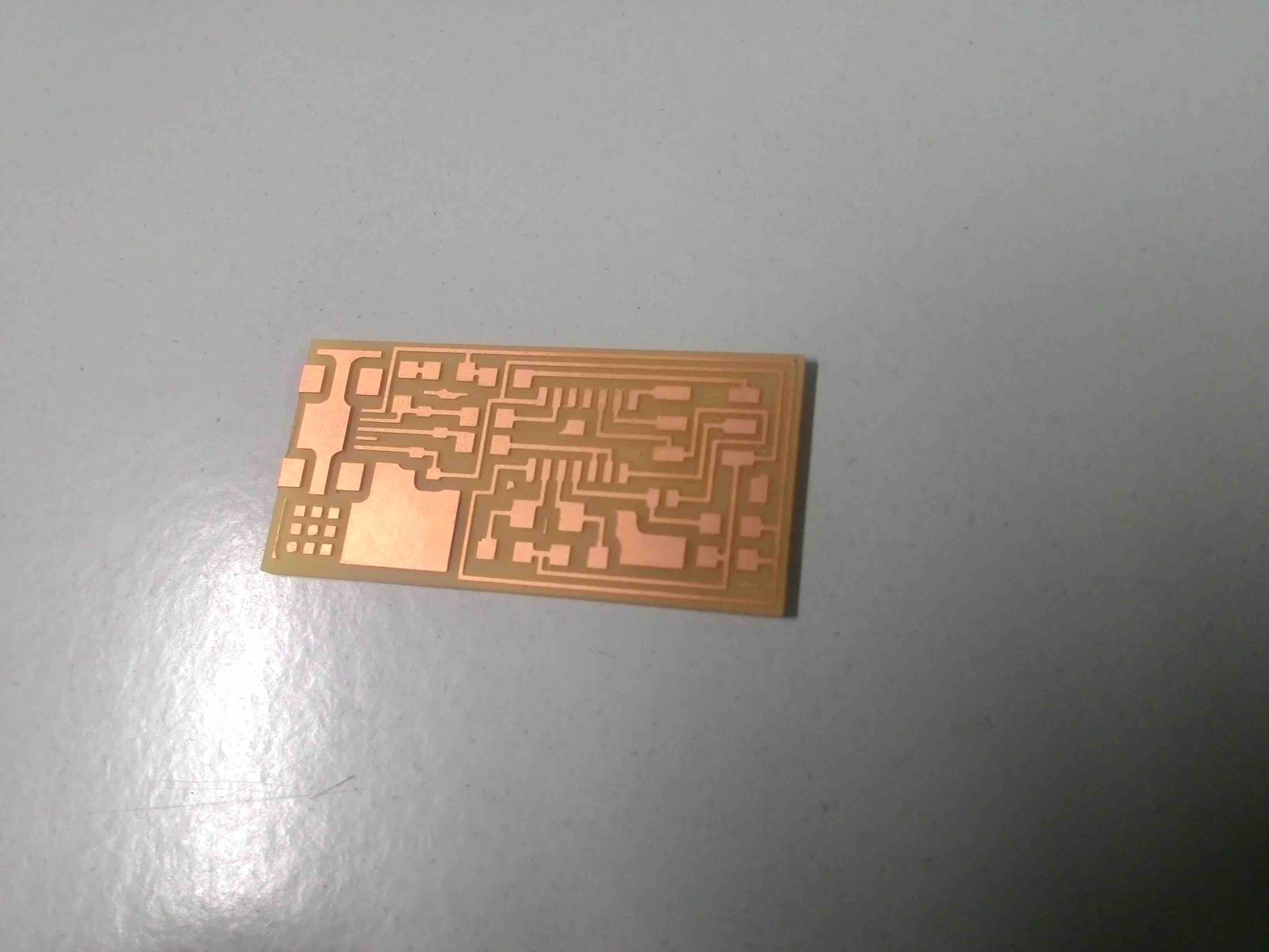
Once the cutting part is done, the board is carefully removed the above photo shoes how the board looks like.
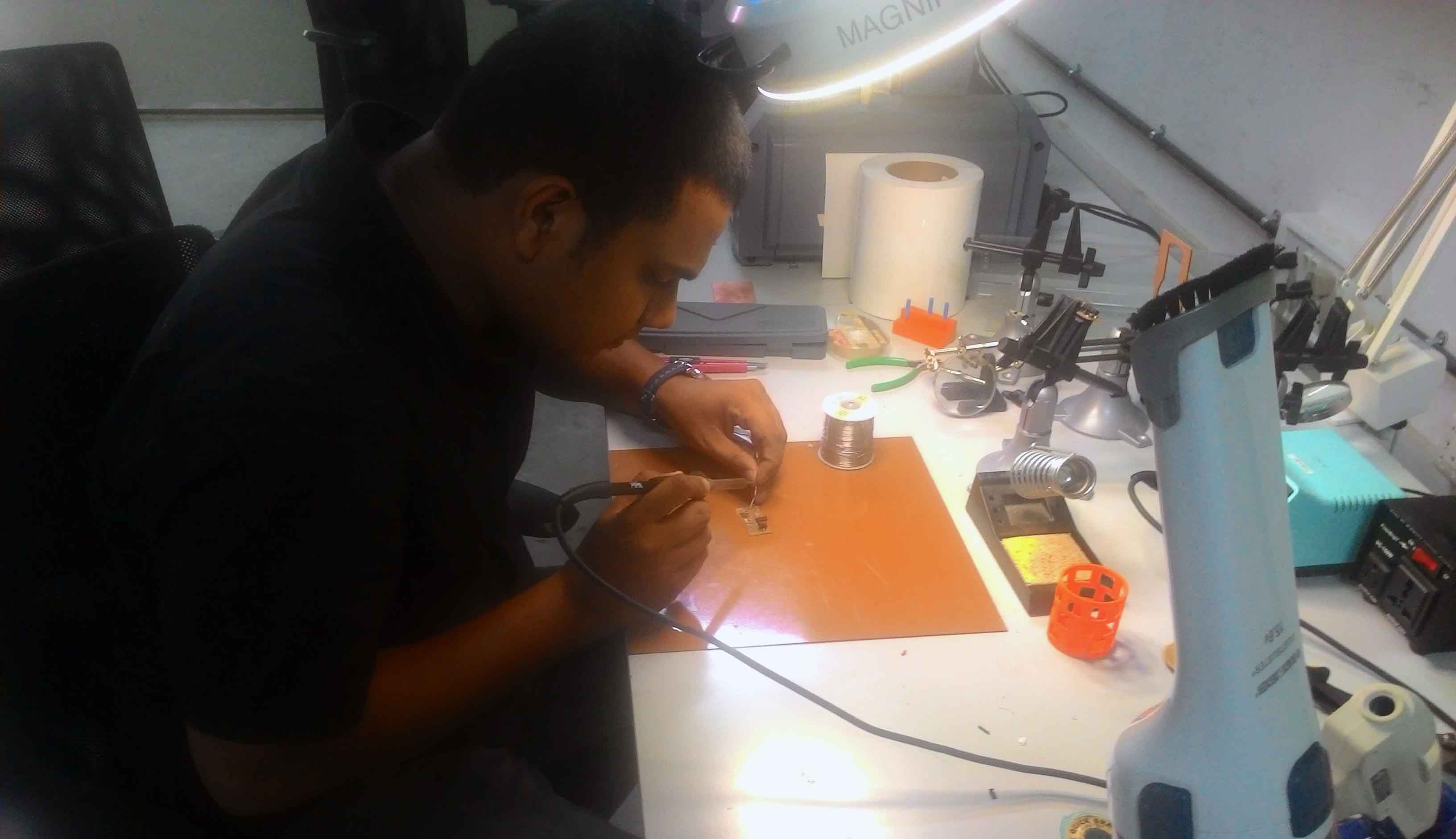
After that its only a matter of picking the right components and soldering it to the board using electronics workbench
Components required
- ATTiny 44 microcontroller : 1
- Capacitor 1uF : 1
- Capacitor 10 pF : 2
- Resistor 100 ohm : 2
- Resistor 499 ohm : 1
- Resistor 1K ohm : 1
- 6 pin header : 1
- Resistor 10K : 1
- USB connector : 1
- Jumpers - 0 ohm resistors : 2
- Cystal 20MHz
- Zenor Diode 3.3V : 2
- USB mini cable : 1
- Ribbon cable : 1
- 6 pin connector : 2
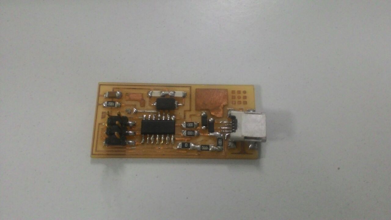
Problem faced
I don't have much experience stuffing the board and hence it was a fun experience altogehter. However, While stuffing the board, I placed ATtiny44 microcontroller in wrong polarity. I tried to take it out but I scratched the surface of the board and few traces got damaged. I could not fix it again and I had to mill a new board and got it right in this second attempt.
Programming FabISP
First we need to install install avrdude / GCC software and dependencies. Once it is done
Open Terminal and type:
 sudo apt-get install flex byacc bison gcc libusb-dev avrdude


    sudo apt-get install gcc-avr


    sudo apt-get install avr-libc


    sudo apt-get install libc6-dev
Then I downloaded the firmware from the page where Fab Academy electronics productions week's details are given:
http://academy.cba.mit.edu/classes/embedded_programming/firmware.zip
I unzipped the firmware and moved it to the desktop
Edit the Makefile
The Makefile is set up to work with the AVRISP2 by default. So the make file was edited and saved.
Program the FabISP
Now in terminal navigate to the folder where FabISP firmware is saved. and then give the following commands
    make clean


    make hex


    make fuse


    make program
Once the board is programmed, remove the 0 ohm resistor and also solder the bridge.
Now the FabISP is all set to rock n roll!
Board design file:
fabispdjtraces.png
fabispinterior.png