| Home | | Weekly Assignments | | Final Project | | Photo Gallery |

Week 11: Input Devices
Assignment for this week was to add a sensor to a microcontroller board that you've designed and take input through it. I looked around for sensors available in the FabLab. There was a ambient light sensor PHOTODARLINGTON NPN CLR PLCC-2.
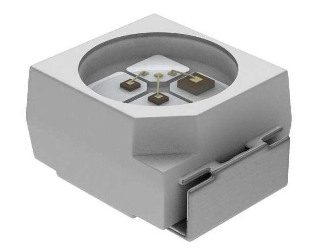
My plan is to add this photo transistor and and LED to an ATtiny44 microcontroller. The LED will be programmed in such a way the LED will light up when the sorroundings turns dark.
The board designing/editing was done in my favorite PCB designing software Kokopelli.
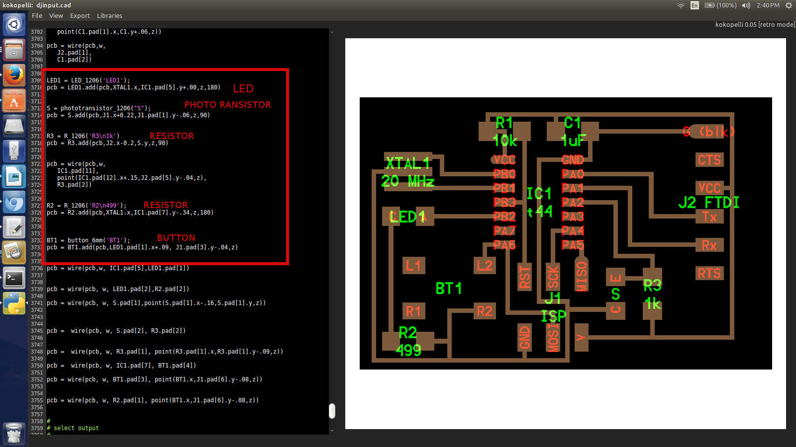
The width and breadth of Neil's board was increased in Kokopelli and the following code along with code for few wires was added to get the final board desing with a Phototransistor, button and LED.
LED1 = LED_1206('LED1');

pcb = LED1.add(pcb,XTAL1.x,IC1.pad[5].y+.00,z,180)


S = phototransistor_1206("S");

pcb = S.add(pcb,J1.x+0.22,J1.pad[1].y-.06,z,90)


R3 = R_1206('R3\n1k')

pcb = R3.add(pcb,J2.x-0.2,S.y,z,90)


pcb = wire(pcb,w,

   IC1.pad[11],

   point(IC1.pad[12].x+.15,J2.pad[5].y-.04,z),

   R3.pad[2])


R2 = R_1206('R2\n499');

pcb = R2.add(pcb,XTAL1.x,IC1.pad[7].y-.34,z,180)


BT1 = button_6mm('BT1');

pcb = BT1.add(pcb,LED1.pad[1].x+.09, J1.pad[3].y-.04,z)


pcb = wire(pcb,w, IC1.pad[5],LED1.pad[1])


pcb = wire(pcb, w, LED1.pad[2],R2.pad[2])


pcb = wire(pcb, w, S.pad[1],point(S.pad[1].x-.16,S.pad[1].y,z))
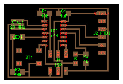
The final desing for the board:
The design was exported in png format as traces and interior with a resolution of 30 pixels from Kokopelli
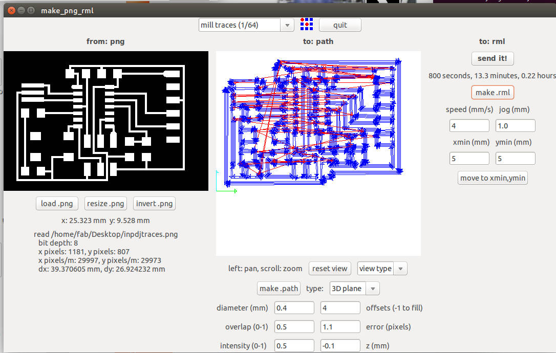
The board was milled using Roland Modella MDX20 through the Fab module.
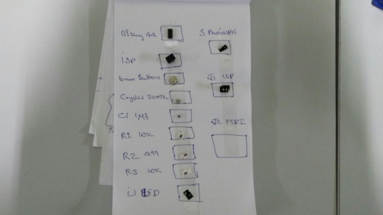
The board was stuffed at the Electronic Workbench using the above SMD components.
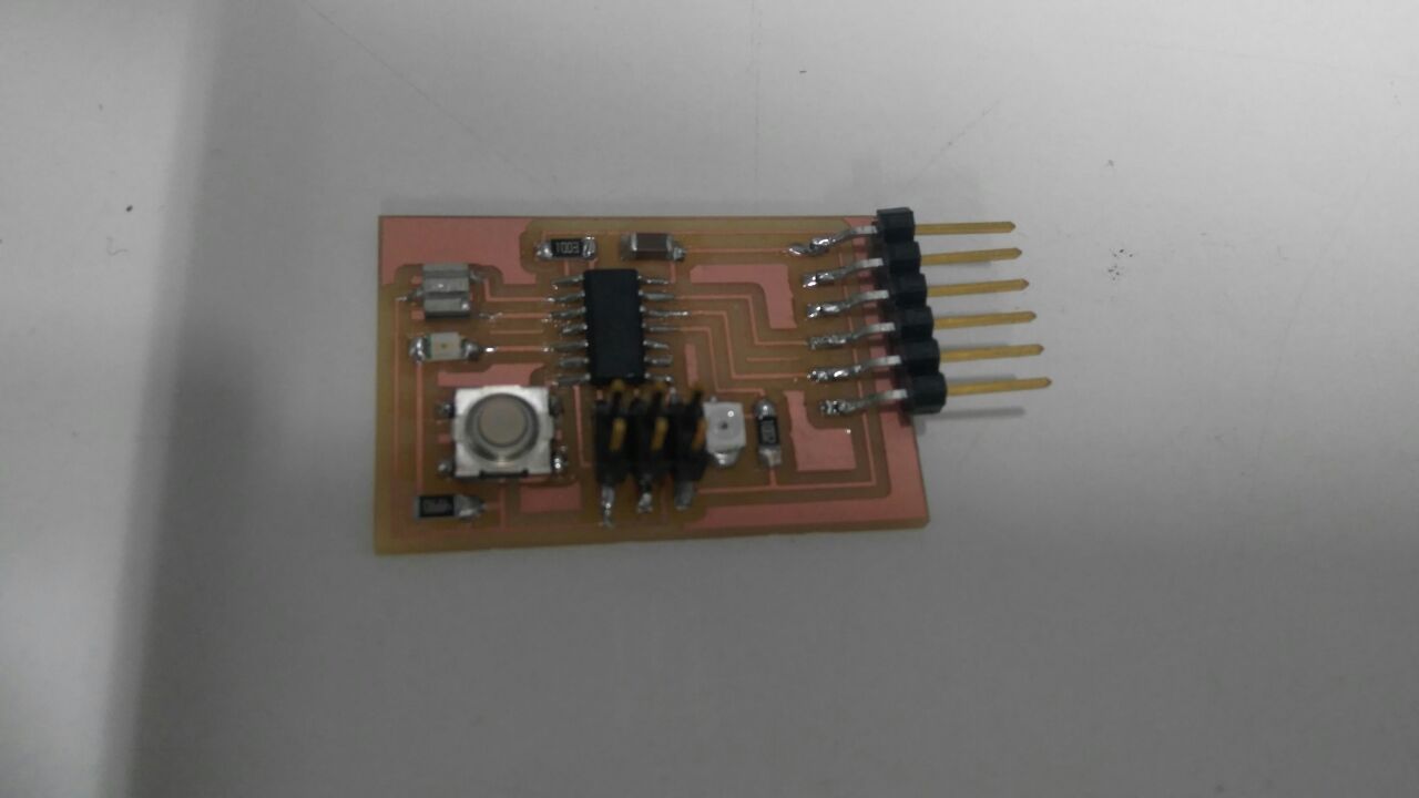
The board is ready now. Next, I burned the bootloader using the Arduino software by keeping the settings as crystal: 20MHz, IC: Attiny44. Next up, I programmed the board to light up the LED on the board when the ambient light is low.
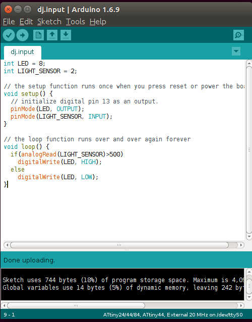
This simple program to light up LED was uploaded to the microcontroller using Arduino software.
The Final output. The Light sensor succesfully detects darkness and lits up LED.
The code used:
int LED = 8;

int LIGHT_SENSOR = 2;


// the setup function runs once when you press reset or power the board

void setup() {

  // initialize digital pin 13 as an output.

  pinMode(LED, OUTPUT);

  pinMode(LIGHT_SENSOR, INPUT);

}


// the loop function runs over and over again forever

void loop() {

  if(analogRead(LIGHT_SENSOR)>500)

    digitalWrite(LED, HIGH);

  else

    digitalWrite(LED, LOW);

}
kokopelli board design file: djinput.cad
Board : djinputboard.png
Board traces file for milling : inpdjtraces.png
Board interior file for cutting the board : djinputinterior.png