Week 14: Composites
Homework for this week:
- Design and make a 3D mold, and produce a fiber composite part in it.
Positive mold for an object with two tubes in Fusion 360
For this week's assignment, I decided to make a structure that consists of two tubes in Fusion 360. I would make it from styrofoam. Although I could make the mold with our large mill (see week 7), I will make it on our Roland MDX-40A mill. Would I be able to do it with the same mill that we normally use for milling our circuit boards?
As I enjoy riding my race bike, the structure I am going to mill resembles a part of a bicycle frame made of carbon fibre (cf. fig. 5). I needed to do two parts in order to be able to mill them effectively. After making the positive mold(s), I would then cover each mold with a layer made of resin and glass fibers, then glue the parts together and wrap around them a second layer of fabric with glass fibers woven into. Finally I would "burn away" the mold.
Design
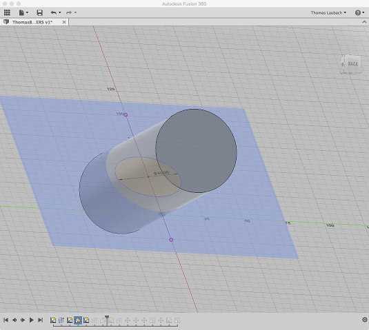
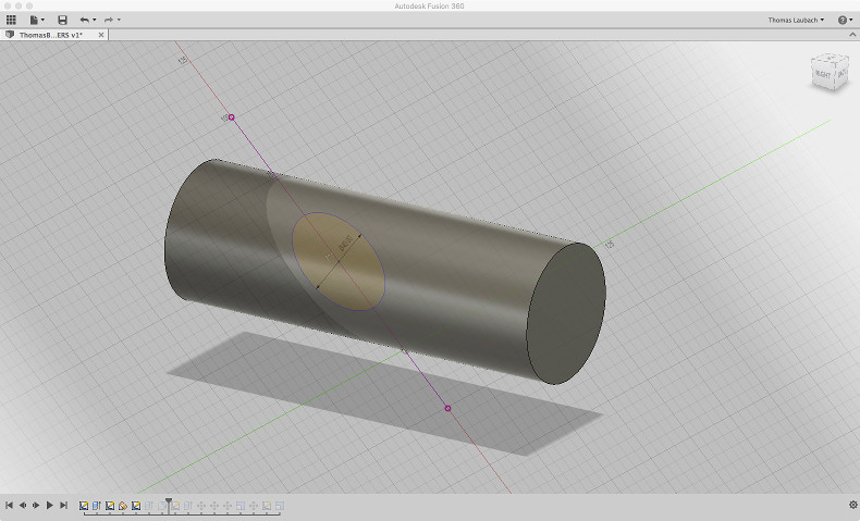
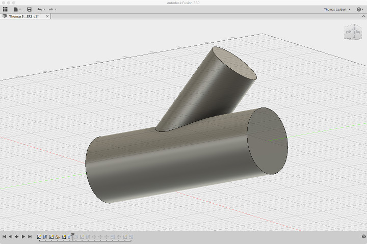
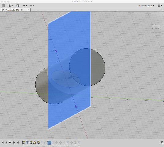
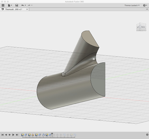
Without going into too many details, I will briefly describe here how I constructed the two parts of my object. For the first tube, I sketched a circle and extruded it up to a suitable length that would still fit in the confines of the Roland mill. I then constructed a skewed plane through the tube (see next image) and sketched a circle with a slightly smaller diameter on it. The midpoint of the circle is on the middle line of the tube. I extruded the circle and got a tube protruding from the first one. Then I added a chamfer where the two tubes intersect. Finally I made an auxiliary plane that exactly divides the body in two halves. With the plane, I extruded the either body into the other and vice versa.
CAM process
The newest "Autodesk Fusion 360" update comes with a nice built-in CAM module. It lets you simulate the milling process with a particular milling strategy and pre-selected tools. Finally I could export my design in the Mastercam Numerical Control File format with suffix *.nc. According to this source, it "contains numerical control instructions for directing machine tools, such as a drill, during production".
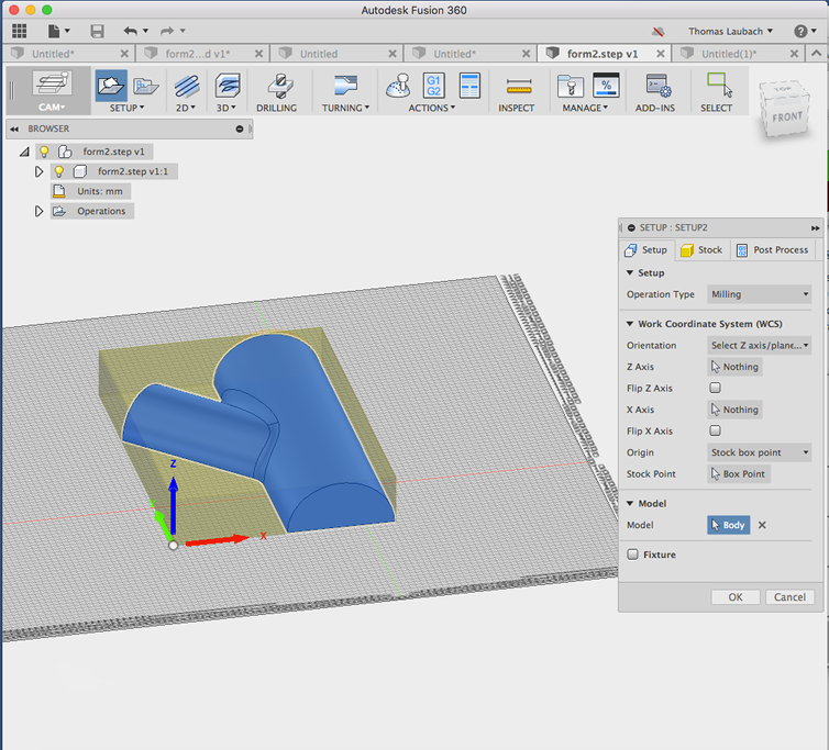
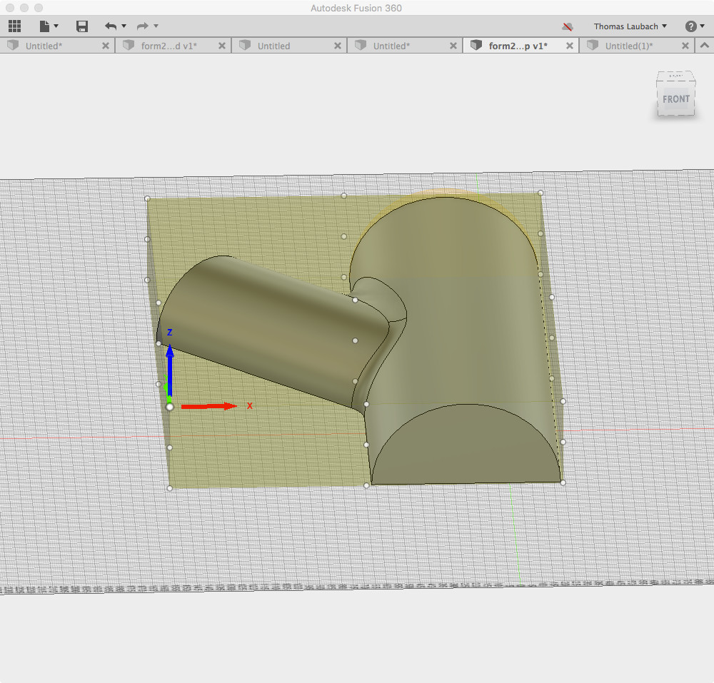
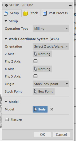
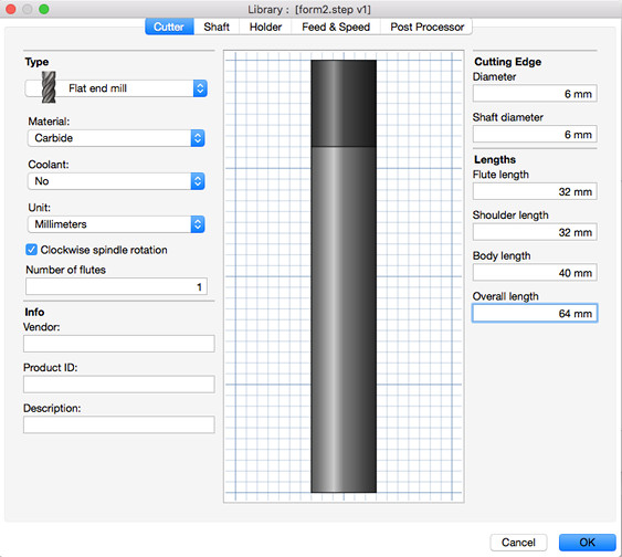
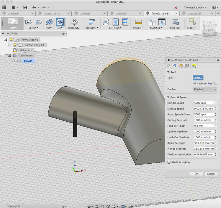
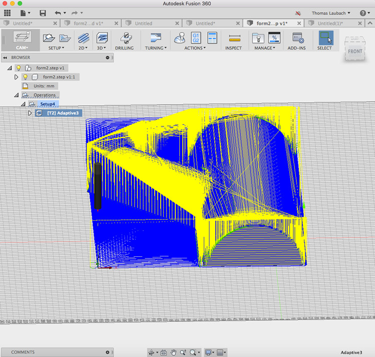
For the CAM process, I changed to CAM mode in Fusion 360. In the Setup dialog, I used the parameters as shown in fig. 8. In the Adaptive dialog, I set the parameters to those visible in fig. 10. The black tube-like object in figure 10 is a symbolization of the end mill I would be going to use. As the end mill were not in Fusion 360's data base, after measuring the values I needed I made my own definition (see fig. 9). It was convenient to re-set the origin of the object to the upper left corner of the box that encloses the object (cf.fig. 7). An ongoing simulation of the milling process using the previously selected strategy is shown in fig. 11.
I scaled the resulting objects so that they had a length of approximately 260 mm. Finally I exported them in the Mastercam Numerical Control File format, *.nc.
Making the mold
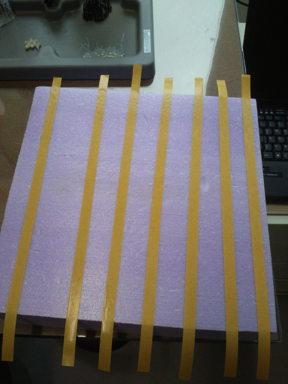
As my object would have the dimension of roughly 260 mm x 260 mm, I used our band-saw to make two styrofoam blocks of suitable size. Once finished, I put double-sided adhesive tape on them to fix them, one after another, on the plate of our Roland MDX-40A mill (see below). 300 mm x 300 mm is the maximum area the mill can process.
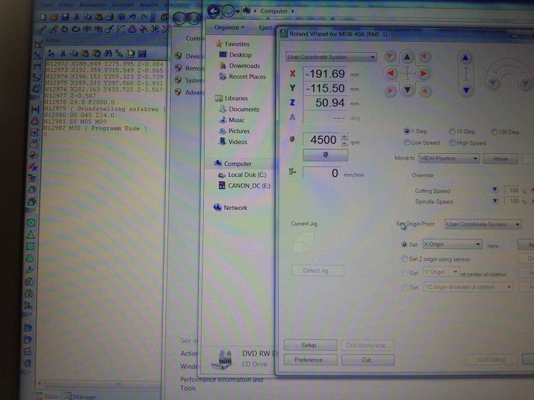
The Roland mill's software goes by the name VPanel MDX-40A. While the best way to prepare milling circuit boards is using the FabModules, this software can be employed for run-of-the-mill milling a three-dimensional body. However, it requires the CAM source to be in format *.nc. Note: it is fairly easy to write a parser for this file format as it is human readable.
One by one, I processed my CAM files (see above section) with the VPanel application:
As for every milling process, I first set the origin of the machine's coordinate system. With VPanel, it is more convenient than with the FabModules. The former offers icons for this very purpose, the latter requires to put the numbers into dialog boxes and confirming them. With VPanel, once you have found a x-y or the z origin that suits you, you declare it accordingly, as can be seen in fig. 5.
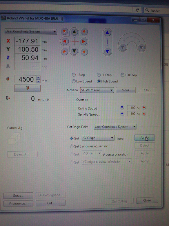
Early in the milling process, I noticed the good surface quality of the mold in production. I set the parameter "Cutting Speed" in the dialog to 150 % first, then 200 %, and 400 % in the end, carefully observing the outcome. I also increased "Spindle Speed" to 150 %. The result is visible in fig. 7.
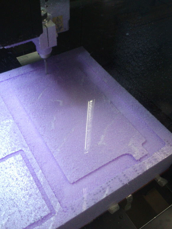
The finished molds look like this:
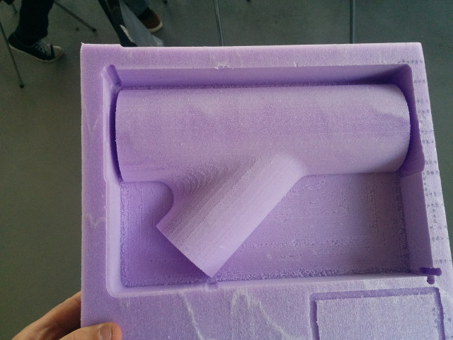
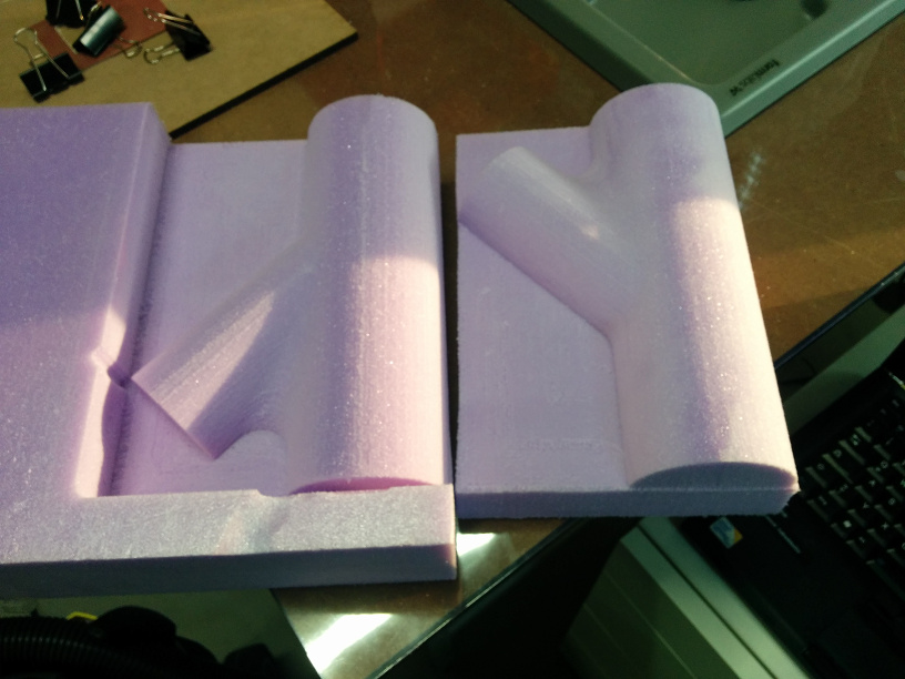
I cut both molds to size with the band-saw. After glueing both halves together, I would have to level the flat surfaces of the mold.
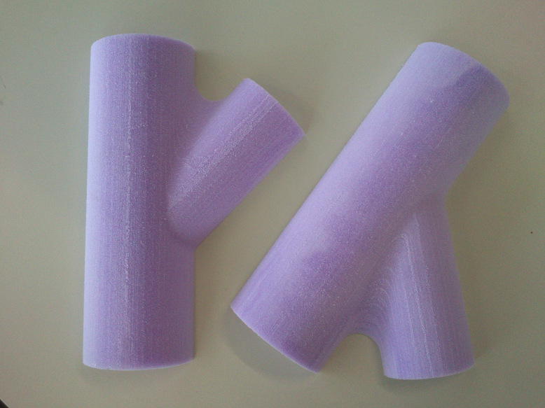
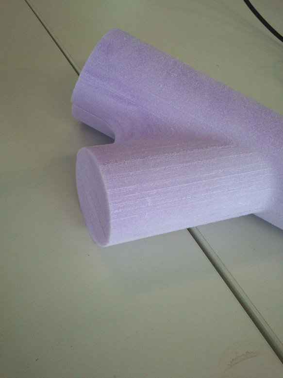
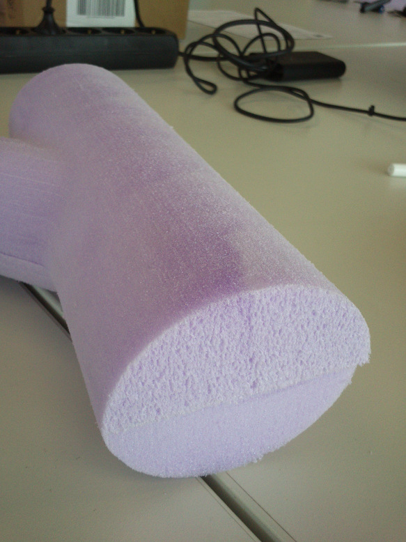
After finishing this part of the process, I cleaned the place with our industry-quality vacuum cleaner, in particular the space around the band-saw and the accessible parts of the machine bed.
Wrapping two layers of glass fibers around the mold
In the following, I would apply two layers of glass fiber, woven into a fabric, onto my two bodies. To be precise, I would apply the first layer on the two halves sequentially.
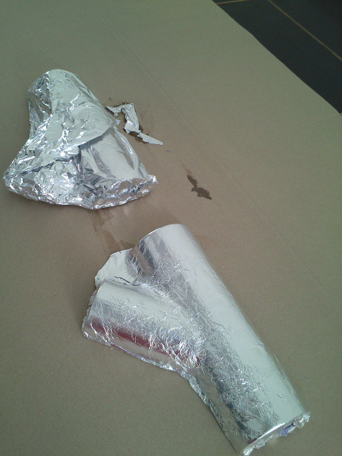
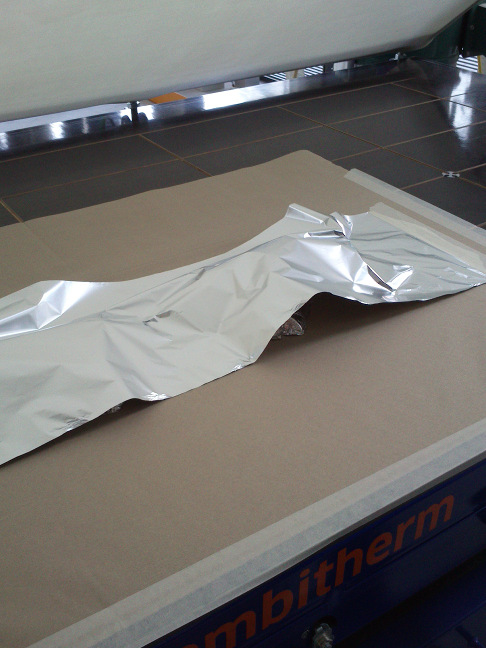
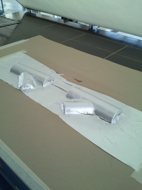
The first step was to generously wrap aluminum foil around the halves, preferably without making holes in the aluminum foil alongside the bodies. The aluminum foil would protect the styrofoam from reacting with the chemicals used in the succeeding steps of the process.
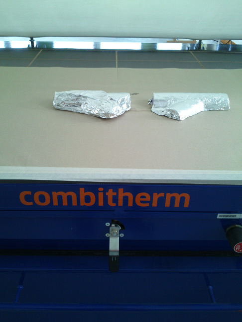
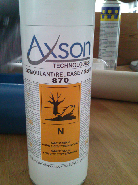
I put the aluminum-coated parts in our Columbus Combitherm thermoformer and vacuum-pressed them over a period of ca. 25 minutes. After that I sprayed Axson mold release agent on the parts, then put another layer of aluminum foil across both parts and vacuum-pressed the parts again over the same time period. After the treatment the aluminum foil formed a dense layer around the styrofoam.
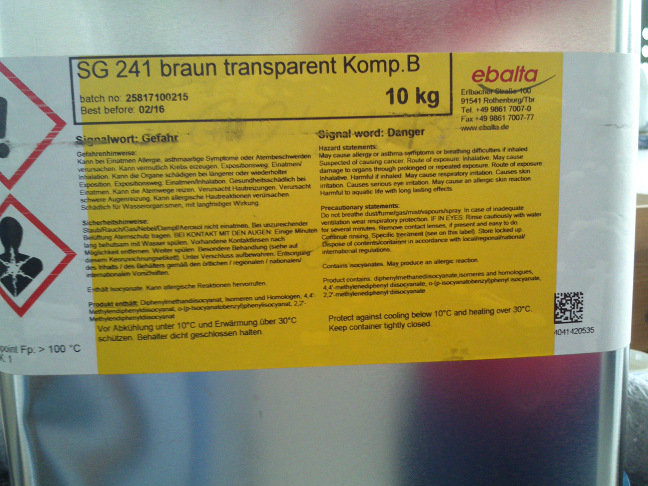
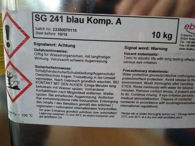
I could now apply the first layer of fiber and resin to the tube halves. Prior to this I prepared a bowl of resin, Presto Polyester Harz, with hardener. I also trimmed some sheets of fabric with fibers woven into them to size. For the following steps, I wore gloves. Although the fabric with glass fibers would not be as harmful as carbon fibers, the dust produced by band-sawing the fibers would.
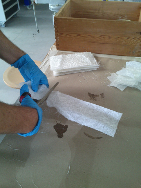
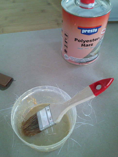
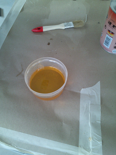
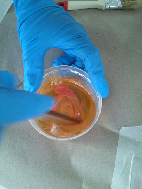
I carefully wrapped the sheets of fabric around the first of the two halves. I needed to be quick in applying resin on them, as the resin would harden very fast. Doing so, I made sure that the fiber sheets with their resin coating fit snugly to the tube. When one thinks about this part of the process, it gets clear why it is almost impossible to create sharp edges with this technique: the fibers simply cannot be bent arbitrarily but need to gently "flow out".
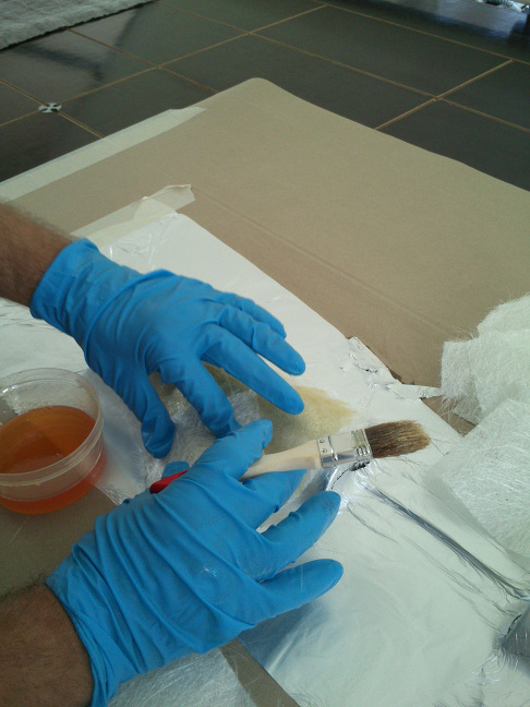
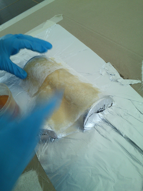
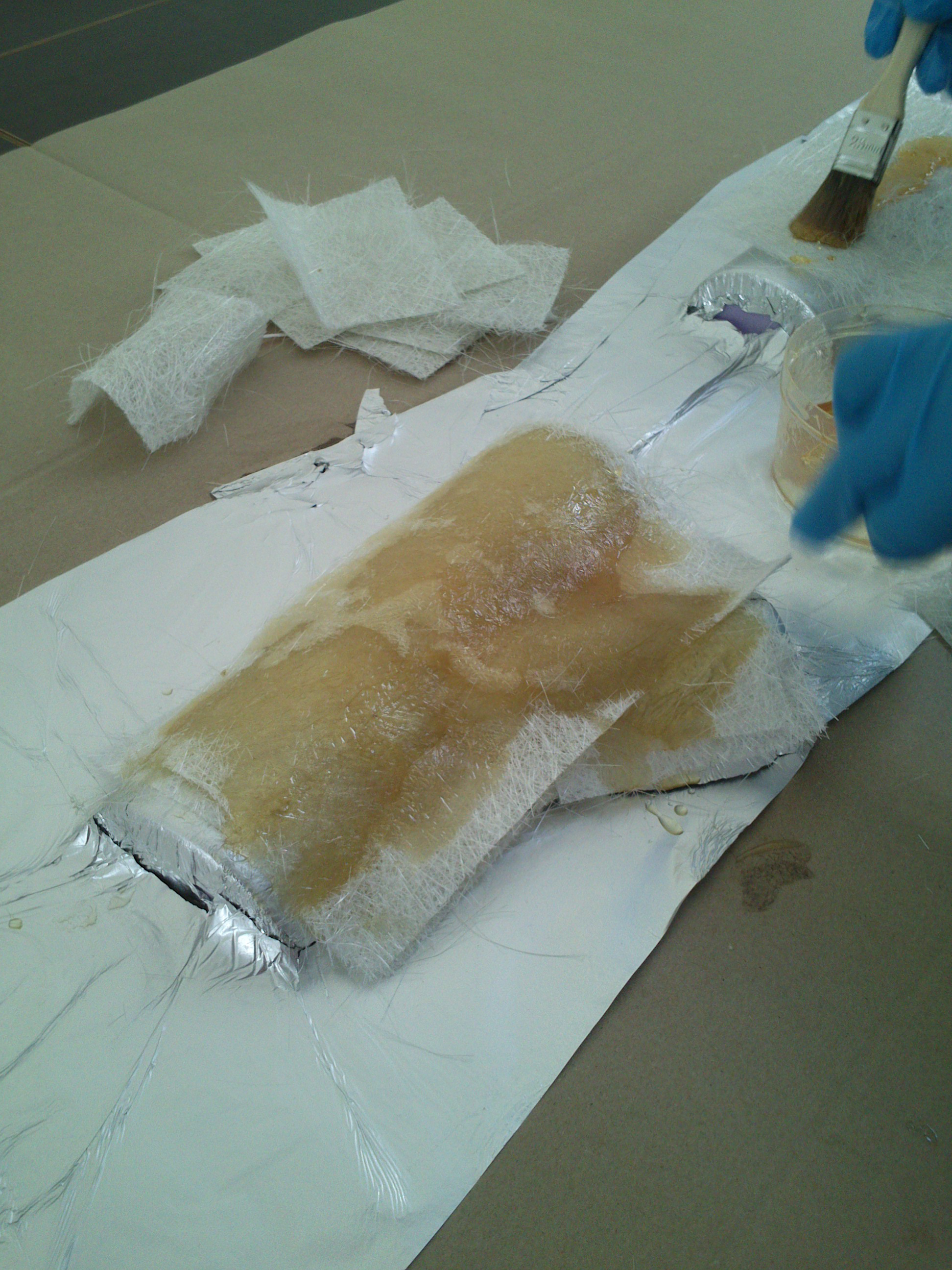
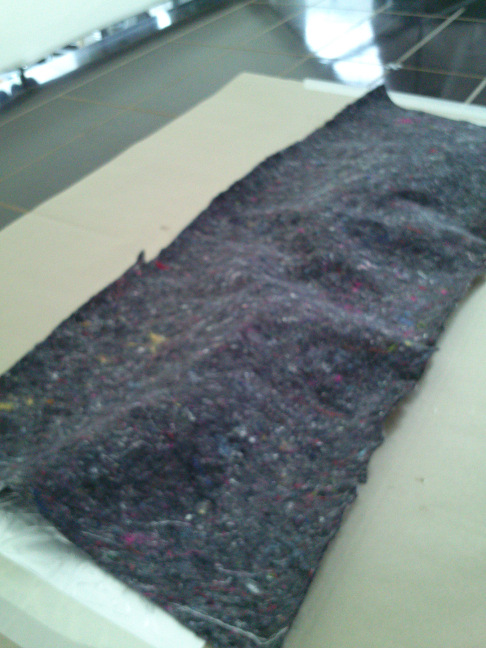
Before I treated my tubes again to vacuum-pressing, I put a fabric over them in order to prevent the inner face of the hood of the thermoformer from being bedrabbled.
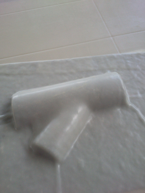

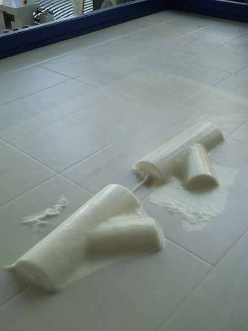
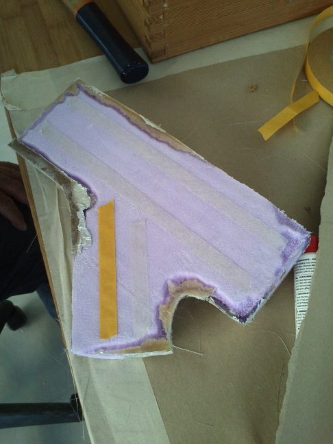
After the first thermoforming session, either of the tubes looked like in the next picture. At most places, the layer made of resin and fibers had formed a nice coat around the tube.
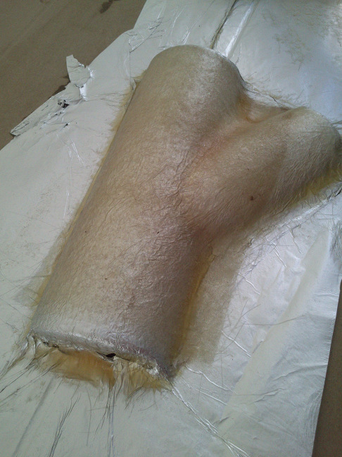
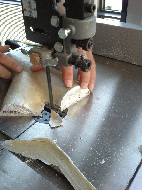
As I would glue both tube halves together later on, I needed to get rid of all superfluous parts of the coat. Where it could be done, I used the scissors, where the material was too hard, I used the band-saw. When I was done, I immediately cleaned the place with the vacuum-cleaner.
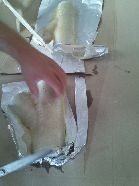
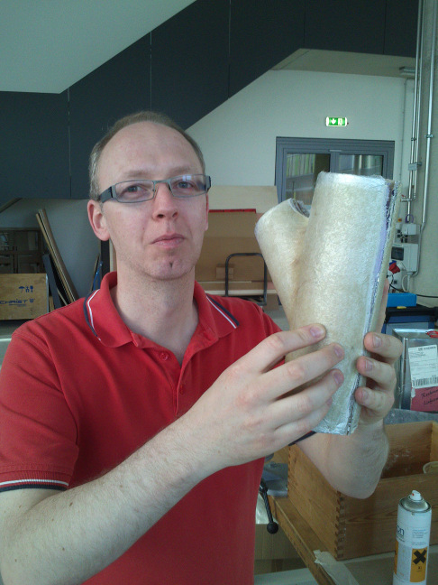
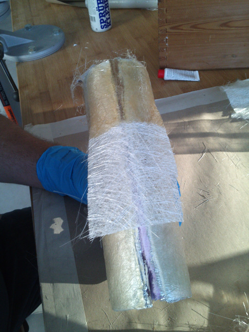
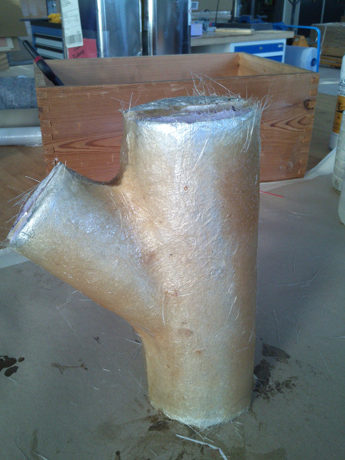
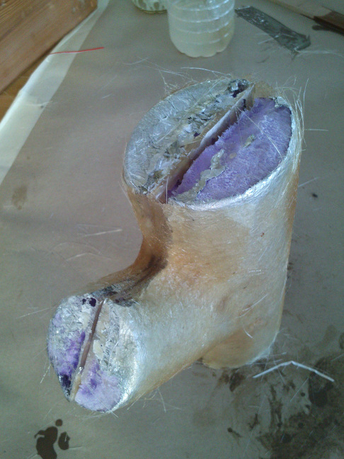
With their first layer of fiber hardened-out, I used double-sided tape to glue the halves together. I then applied the second layer of fibers and resin, following the strategy described above. When I had done this, I applied the tube to treatment in the thermoformer again for 30 minutes. The result is shown in below images.
Removing the inner parts of the tubes
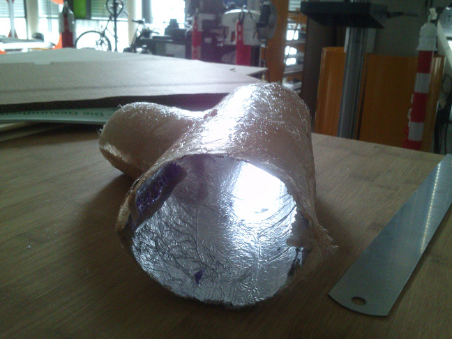
The last part of the process is to remove the inner parts of the structure. In the end, the hollow body made of my two tubes would prevail. For a real project, an extra step would be to make the surface smooth and nice (grinding, varnishing, priming, etc...). I have removed the styrofoam by dropping acetone through the tube(s), please see below picture. The aluminum will stay in place. I could make the tubes much prettier, but I have not done this because this is likely to adverse my health.
Source files
Fusion 360 design files of the molds: here and hereBoth files in format *.prn in a ZIP file: here
Lessons learned
- I learned how to make a mold from two parts.
- I learned how to make a coating made of glass fibre and resin.
- I can now appreciate how much care and effort is necessary to design a car body made of carbon fibre.