Week 11: Input Devices
Homework for this week:
- Make your own board with a sensor and read it.
Building a USB joystick for a PC
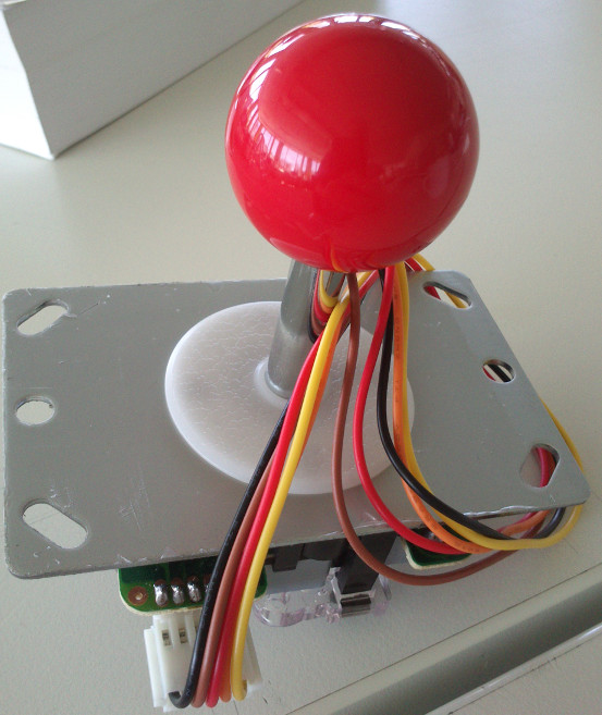
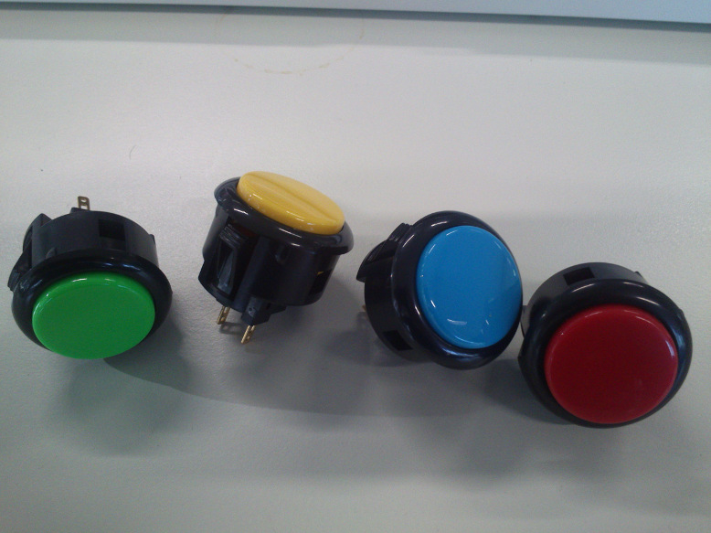
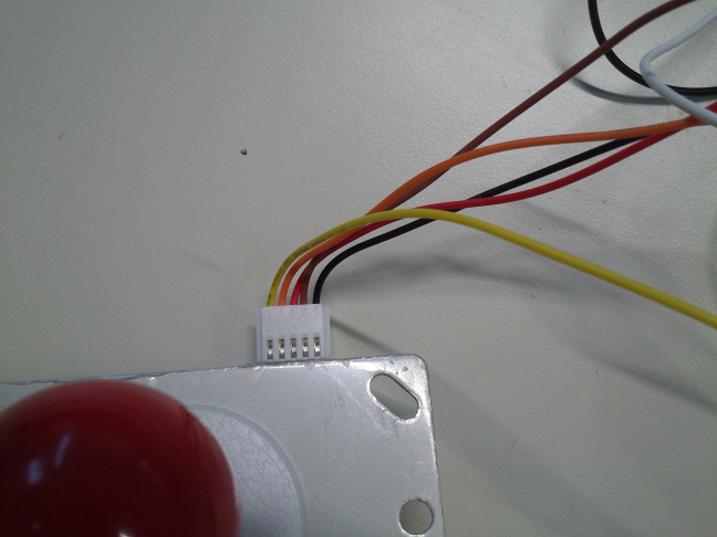
For this week's assignment, I wanted to build something for fun. Grown up in the Apple 2 and Commodore 64 era, I am used to using joysticks in video games. While the Competition Pro is a fine joystick for computer games, I wanted to have something more arcade-like for my MAME (Multi Arcade Machine Emulator) emulator (here). I bought an Arcade joystick from Exp-Tech and Arcade buttons from www.arcadeshop.de (see images).
Designing a PCB in EAGLE
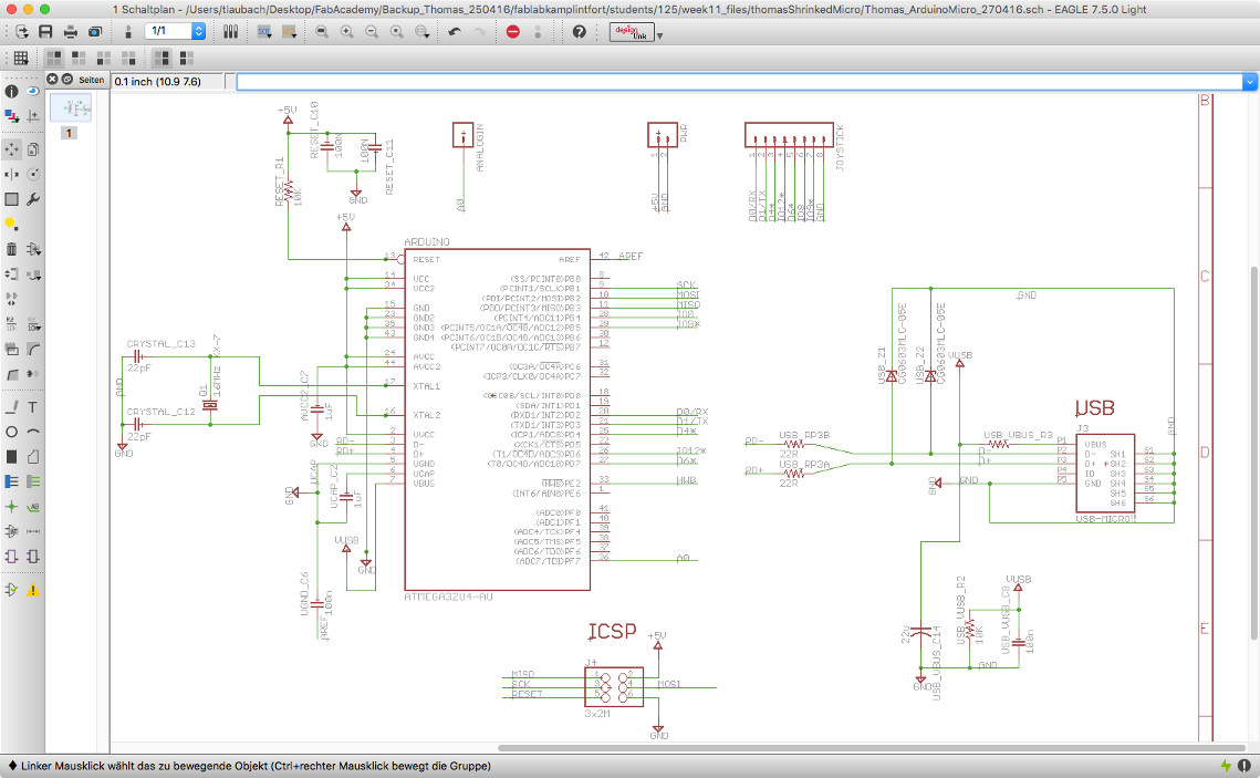
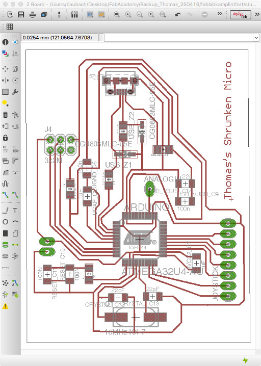
As I like the Arduino family, I want to use one. There are two issues with that: I need to build the microcontroller board myself, and the PC does neither recognize the Satshakit nor an Arduino Uno as a USB device. This is why I did a design which is based on an Arduino Micro. The Micro uses the ATmega32U4 microcontroller that features a built-in USB (see https://www.arduino.cc/en/Main/ArduinoBoardMicro).
In EAGLE, I modified the original Arduino Micro board schematic by stripping down the following components I would not need:
- Voltage regulators
- On-board LEDs
- Miniature button
- Some Digital pins
- All but one Analog pin
I added two pin headers, one for the single Analog pin I would use, a twin header for power, and an eight pin header for the joystick. The Analog pin header can be used for a paddle controller in the future. This is especially suited for Breakout-style games.
Milling the PCB on a Roland MDX-40A
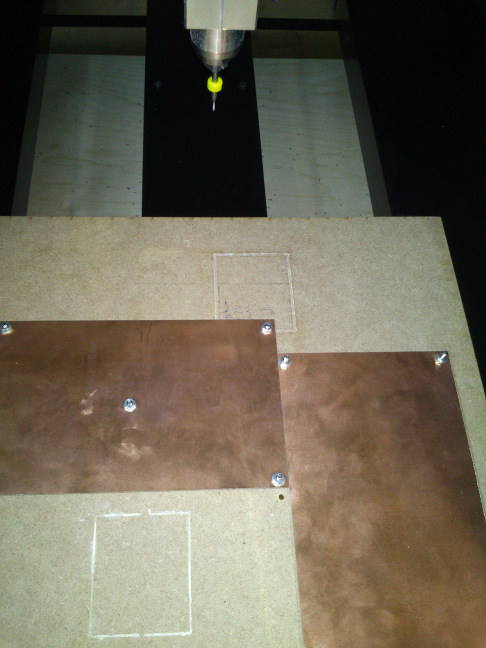
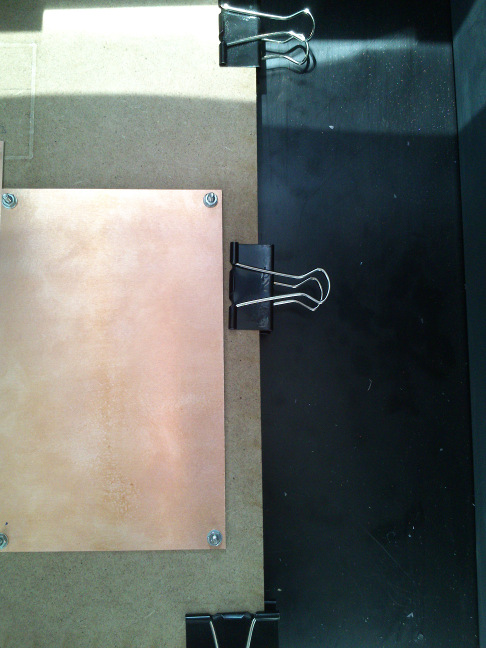
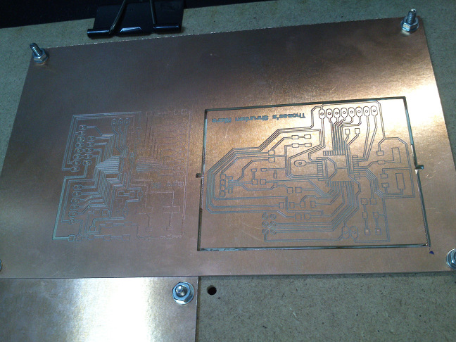
For this project, I could use our Roland MDX-40A mill and the FabModules, thanks to Daniele Ingrassia, our Fab Guru, who made it work. This mill requires at least a two-pass approach to milling. First, the traces are milled with an engraving head. Then, the outline is milled with a suitable cutting head. On the MDX-40A (see below image), we need to change the milling head manually. It is taken for granted that the copper board is hold tight in its place for both successive steps. We did this with clamps and screws like shown in the pictures.

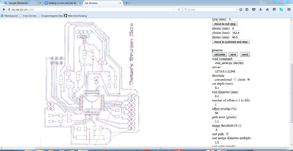
First, I needed to start our FabModules locally, then load my binary image with the traces that I had made with GIMP. It is important that this image maintains the same dimensions as the original board image. The same holds true for the binary image with the border only.
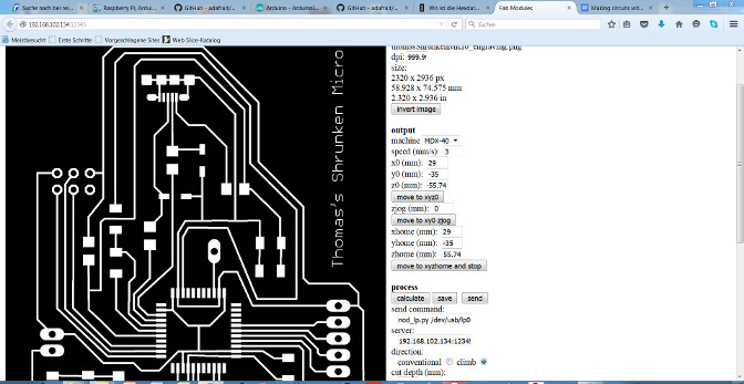
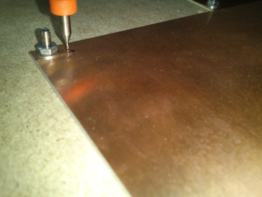
As next step, I needed to set the zero position in the machine coordinate system. For this, I first marked a position on my copper plate that would later be the zero position (cf. below image). I then used the buttons on the Roland mill's control panel to move the milling head above this position, keeping the head far enough from the board. Once satisfied, I tell the machine the new zero position by reading the x,y-coordinates from the panel and typing them into the dialog window on the computer as xhome, yhome. As the FabModules module for our Roland mill is not exactly tailored to it, there are some minor glitches. One glitch is that after every coordinate change I need to set parameter zjog (mm) to 0.
It is vital to not forget to zero in the vertical position of the milling head (z).
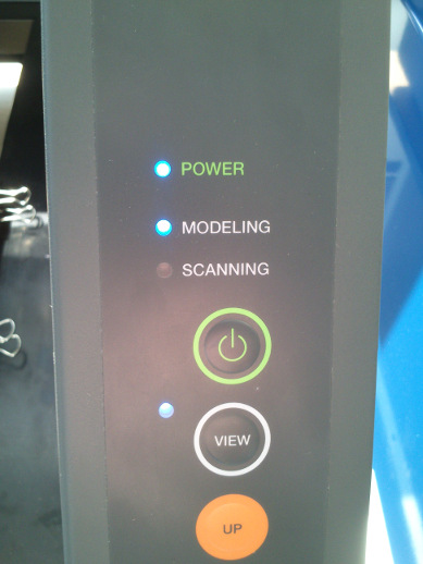
For this, one should start to lower the head by some centimeters first, then by millimeters, and so on. In the end, the end of the milling head shall barely touch the copper plate. The z-position, once found, must also be entered into the FabModules dialog at zhome (mm). During these adjustments and during the milling process, it is useful that the Roland mill allows you to stop the current process, lets you inspect the result, and then proceed with the process. This is facilitated by pressing the button View on the machine panel, and afterward holding it down until the machine proceeds. Here it is vital to wait for the extruder head to stop moving before opening the lid of the machine.
These are the final parameters I used for engraving the traces:
- machine: MDX-40
- speed (mm/s): 3
- cut depth (mm): 0.12
- x0 (mm): 29
- y0 (mm): -35
- z0 (mm): -55.74
- direction: climb
- send_command: nod_lp.py /dev/usb/lp0
- server: 192.168.102.134:12345
- number of offsets: 1
The remaining parameters I left unchanged.
The parameter number of offsets decides how many times a position on the board is milled. I had to experiment with the cut depth during the milling process, as some traces were not deep enough and allowed for current flow. Finally I milled the board from scratch with cut depth 0.12 mm.
For the border, i.e. the outline, I changed the cut depth to a value that is the thickness of the copper plate plus 0.05 mm. I also changed the extruder head, as cutting would require a different one.
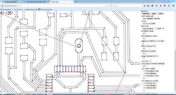
Whenever a parameter in the FabModules is changed, the tool path needs to be calculated anew. This is done by pressing the Calculate button.
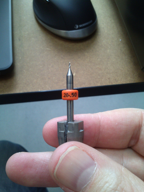
For engraving, I used a 0.2 mm head that I needed to change manually in the mill. While doing so, you obviously need to avoid touching the sharp end of the milling head so to not become injured or harm the tool.
With the script "bom.ULP" in EAGLE, I obtained a dialog window that allows to export a bill of materials for a project (see below image). You can export the data in either text format, HTML, or in CSV (comma separated values). I am now waiting for some electrical components to arrive. After that, I can go ahead with the soldering.
The following image shows the tool paths of the milling head for my board design.
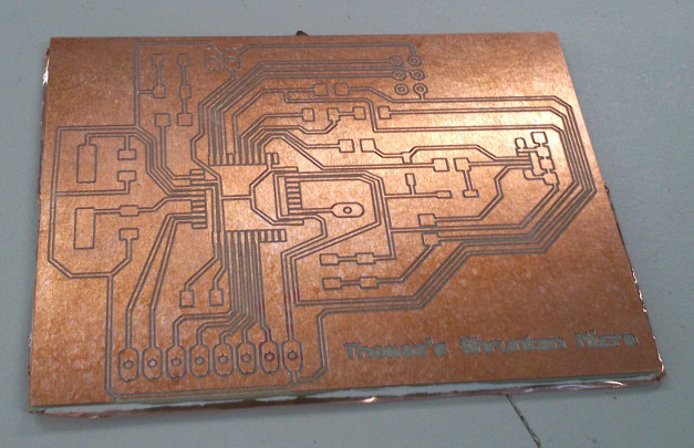
After engraving the traces and cutting the border, the finished board looked decent (see below image) with clearly separated traces. I also validated the electrical connections with a multimeter.
Soldering the components
I have added the resistor by the name "USB VBUS R3" that serves as a "bridge". Its value should be 0 Ohm, therefore. The two components named "USB_Z1" and "USB_Z2" are varistors, although they resemble Zener diodes. Although one person recommended that, I am not sure whether I can replace the varistors by Zener diodes. I did some research in the World Wide Web. Obviously, most people use Zener diodes and varistors interchangeably. With the Arduino Micro, they are used to prevent over-voltage from the USB. I need to keep in mind that, due to their functioning as a current blocker up to a certain voltage, I must solder them "backwards" in comparison to normal diodes.
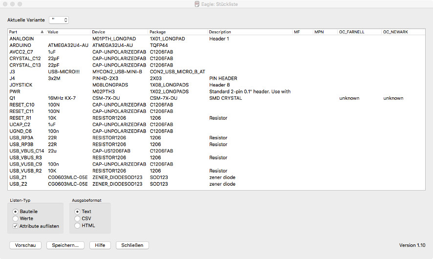
When you export the bill of materials in text format, you get something like the following:
        Stückliste exportiert aus /Users/tlaubach/Desktop/FabAcademy/kalirepo/fablabkamplintfort/students/125/week11_files/ShrunkenMicro/ShrunkenMicro_EAGLEschematic/Thomas_ArduinoMicro_270416.sch am 13.05.16 14:32

Part         Value         Device             Package             Description                          MF MPN OC_FARNELL OC_NEWARK
ANALOGIN                   M01PTH_LONGPAD     1X01_LONGPAD        Header 1
ARDUINO      ATMEGA32U4-AU ATMEGA32U4-AU      TQFP44
AVCC2_C7     1uF           CAP-UNPOLARIZEDFAB C1206FAB                                                                            /Users/tlaubach/Desktop/FabAcademy/kalirepo/fablabkamplintfort/students/125/week11_files/images/billOfMaterials.jpg
CRYSTAL_C12  22pF          CAP-UNPOLARIZEDFAB C1206FAB
CRYSTAL_C13  22pF          CAP-UNPOLARIZEDFAB C1206FAB
J3           USB-MICRO!!!  MYCON2_USB-MINI-B  CON2_USB_MICRO_B_AT
J4           3x2M          PINHD-2X3          2X03                PIN HEADER
JOYSTICK                   M08LONGPADS        1X08_LONGPADS       Header 8
PWR                        M02PTH3            1X02_LONGPADS       Standard 2-pin 0.1" header. Use with
Q1           16MHz KX-7    CSM-7X-DU          CSM-7X-DU           SMD CRYSTAL                                 unknown    unknown
RESET_C10    100N          CAP-UNPOLARIZEDFAB C1206FAB
RESET_C11    100N          CAP-UNPOLARIZEDFAB C1206FAB
RESET_R1     10K           RESISTOR1206       1206                Resistor
UCAP_C2      1uF           CAP-UNPOLARIZEDFAB C1206FAB
UGND_C6      100n          CAP-UNPOLARIZEDFAB C1206FAB
USB_RP3A     22R           RESISTOR1206       1206                Resistor
USB_RP3B     22R           RESISTOR1206       1206                Resistor
USB_VBUS_C14 22u           CAP-US1206FAB      C1206FAB
USB_VBUS_R3                RESISTOR1206       1206                Resistor
USB_VUSB_C9  100n          CAP-UNPOLARIZEDFAB C1206FAB
USB_VUSB_R2  10K           RESISTOR1206       1206                Resistor
USB_Z1       CG0603MLC-05E ZENER_DIODESOD123  SOD123              zener diode
USB_Z2       CG0603MLC-05E ZENER_DIODESOD123  SOD123              zener diode
Working joystick example with a Satshakit
May 23rd.: I have not yet managed to solder the shrunken Arduino Micro board. I will finish this assignment with a Satshakit I have made but would like to solder the Micro board when time permits.
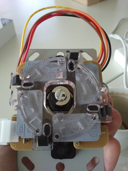
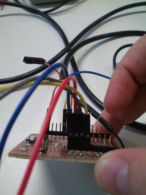
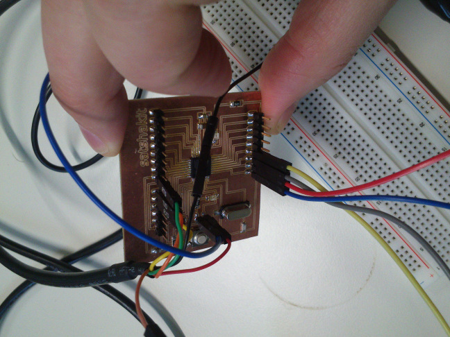
I connected the Adafruit Arcade joystick shown above to my Satshakit. The joystick comprises of four independently usable switches with "Normally Open (NO)" characteristics. This means no current will flow through the joystick when it is not pushed in any of the eight directions. The black wire from the joystick needs to be connected to GND, the remaining four wires represent the UP, DOWN, LEFT, RIGHT (or NORTH, WEST, EAST, SOUTH) directions. I connected them to the Satshakit's digital pins 5 - 8. For the digital pins, I activated their internal pull-up resistors. I did not use a fire button for this demonstration. A fire button would be treated like the other switches. For programming, I have also attached an FTDI cable to the Satshakit (see below image).
On the software side, using the internal pull-up resistors has an interesting side effect: the scan logic for the joystick needs to be reversed. When the joystick is left alone, the voltage at the digital pin is HIGH, and LOW when the joystick is pushed in one of the four directions. If the joystick is pushed diagonally, the voltages at two digital pins are LOW.
I wrote below small Arduino sketch that demonstrates how an Arduino can accept and interpret input from the Adafruit Small Arcade joystick. There is a nice tutorial on how to use the joystick with an Arduino Leonardo here as a USB keyboard device. Although the Arduino Uno cannot mimic a USB keyboard without extra labor, it can query the joystick.
// This small program demonstrates how an Arduino Uno Sketch can read input from the Adafruit digital Arcade joystick
// (see https://www.adafruit.com/product/480 and https://brainy-bits.com/tutorials/leonardo-arcade-controller/)
// Author: Thomas Laubach
// Include libraries for adafruit matrix
#include
The sketch has specific code for using the Adafruit 32x32 RGB Matrix Panel. As soon as the libraries for the LED matrix panel are used which happens when the LED matrix gets initialized, the program stops working. Instead of printing to the serial port a message whenever one of the directional switches on the joystick are being operated, it permanently reports that the joystick has been pulled even if this is not the case. I can only speculate why this happens. It might be due to that no wires between LED matrix and Arduino were connected. This means the pins necessary for controlling the LED matrix were floating but read and used by the program. Incidentally, the computer reported that the USB port the Arduino was linked to consumed too much power.
Over the day, I tried to solve the incident using different strategies. One was to provide current to the circuit because I had and have trouble to understand what makes the joystick circuit work although no current was sent into the joystick. The result I got was basically the same. One colleague suggested to reverse the current flow. I fed 5V into the black wire of the joystick and attached the other wires to the digital pins of the Satshakit, always with the internal pull-up resistors activated to prevent overcurrent. It would have been more efficient to consistently measure the wiring as I was loosing time with guessing and trial and error.
The fact that the program did not work together with the LED matrix and its libraries bothers me. So far, I could only guess but not track down the cause for the faulty behavior of the circuit and the program.
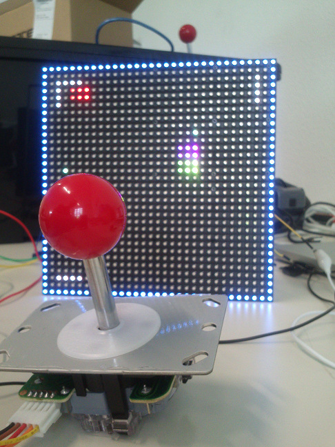
My VGS Board with Joystick and LED RGB Matrix Panel
I have tested the joystick as an input device and the LED matrix panel as output device with the board that I have made for my final project. It works flawlessly. Please watch the movie below for some impressions.
Source files
EAGLE schematic and board files for the Shrunken Micro board:
here
Roland mill image files for engraving the traces and cutting the border of the board:
here
My small example program for querying the Adafruit Small Arcade joystick: here
Lessons learned