Week 5: 3D Scanning and Printing
Homework for this week:
- Group project: Test design rules for all available printers. How thin a wall, how sharp a corner, how close a clearance can we make, with which materials?
- Design and print an object that you cannot make subtractive.
- Scan an object. Print it, eventually.
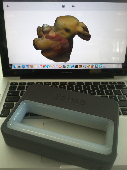
3D Scanning with a 3DSystems Sense scanner
For scanning, I picked a stuffed animal, an Easter plush rabbit that is roughly 25 centimeters tall.
I performed the scanning with a 3DSystems Sense scanner. The rabbit (cf. fig. 1) was sitting on a stand
someone else had made of cardboard.

While I was scanning the rabbit, I slowly walked around it while maintaining a
distance of around half a meter up to a meter and varying the camera angle between roughly 5 and 90 degrees.
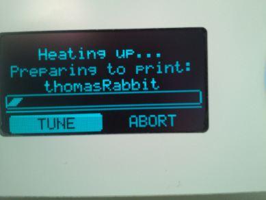
A one moment later in the process, the Sense scanner (see fig. 2) reported to have lost tracking. Upon visual inspection
of the resulting geometry, I believed to have collected enough data and stopped the scanning process.
I have not adjusted any of the scan parameters for the Sense scanner. After saving the resulting object
in the ply format,
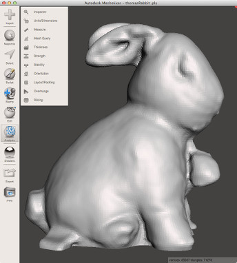
I reopened it in Autodesk Meshmixer in order to have a look at the reconstructed geometry. I noticed at the bottom of
the object some rough edges at the periphery that are likely to result from the cardboard stand. I manually removed some of the
cardboard base. I smoothed out some rough edges with "Analysis/Inspector/Auto Repair All" with the setting "Hole Fill Mode: Smooth Fill".
I was pleased with the result (see fig. 3). As the last step, I exported the geometry as STL format and OBJ format. I would later open the rabbit
geometry in Cura to print it on one of our Ultimaker 2 3D printers.
Photogrammetric reconstruction of the rabbit with VisualSFM
For this week's assignment on 3D Scanning, I also tried to reconstruct the Rabbit object
using a photogrammetry approach. Using my stock Sony Xperia U smart phone, I took 89 photographs
(find them in my DropBox in this folder) of the rabbit that I had put on a cardboard stand. I walked round the object, keeping a
distance of about half a meter up to a meter and varying the camera angle carefully between 10 and 90
degrees. I estimate that the greatest distance between two shots was less than 15 centimeters.
For reconstruction, I used the VisualSFM application (grab it from here) on a Windows 7 64bit equipped machine which means "A Visual Structure
from Motion System". To enable dense reconstructions of a scene, I had to install the software package CMVS/PMVS from here. Please note
that the original link to the software on the VisualSFM page is dead. As first step, I selected all pictures with the rabbit in VisualSFM's open file dialog (File/Open Multi Images),
thereby instructing VisualSFM to load the images into memory and to create preview images. I then did a sparse reconstruction of the geometry ("SfM/Reconstruct Sparse"), then a dense reconstruction ("SfM/Reconstruct Dense").
The latter uses an approach invented by Yasutaka Furukawa (CMVS/PMVS). I inspected both representations using the commands "View/NView 3D Points" and "View/Dense 3D Points", respectively. The data for the dense reconstruction
was saved in the folder LindtHase in the file LindtRabbit_Dense.nvm and in the sub folder LindtRabbit_Dense.nvm.cmvs. For this project, I made a ZIP file and loaded it into my Dropbox
(grab the ZIP file here). Please note that surreptitious advertising is not intended.
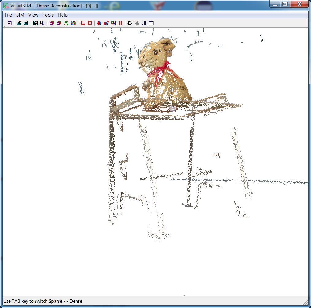
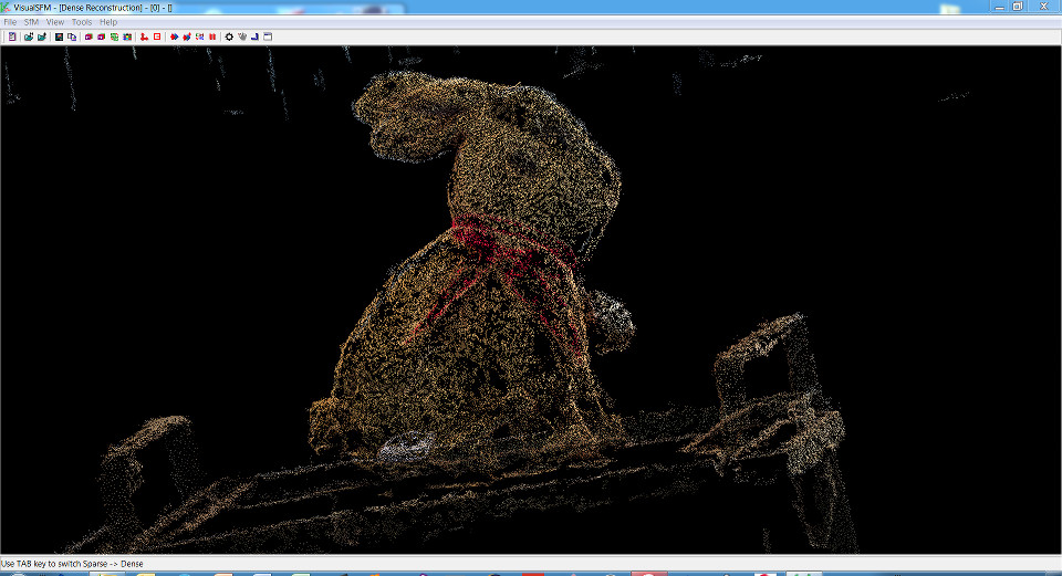
Eyeballing the sparse representation of the rabbit scene as depicted in figs. 4a and 4b, it seems logical that much more photographs of
the scene are needed. Although the texture of the rabbit's surface has been recovered fairly well, many more
photographs are required to close the surface. If one wanted to also capture the cardboard stand, considerably
more photographs from a lower angle are necessary (see fig. 5).

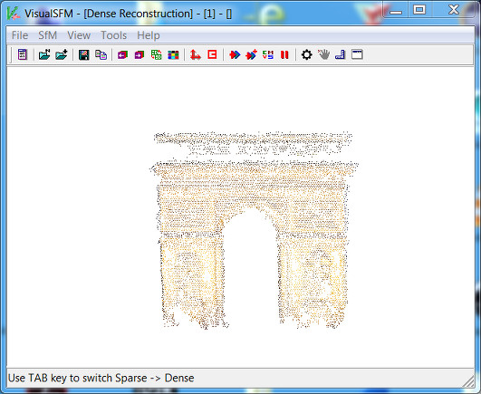
Photogrammetric reconstruction of pictures of the Arc de Triomphe
I was interested in the question, whether an object can be reconstructed using photogrammetry,
although the photographs used stem from different cameras.
I did an Google image search on the word Arc de Triomphe and obtained about 75 images, some
of which do not even depict the Arc de Triomphe in Paris but another arc. The pictures are unrelated.
They have been shot on different days, with different weather, with different cameras, etc.
Therefore, it is surprising how pleasing at least the front
of the Arc de Triomphe looks/how well it could be reconstructed. After loading in all images, I first performed
a "Pairwise Matching/Compute Missing F-Matrix" operation, then "Reconstruct Sparse" and "Reconstruct Dense".
Fig. 6 shows the dense 3D points reconstruction of the Arc de Triomphe. However, here too, it is obvious that the method demands way more photographs.
The files for the project are in my DropBox in the ZIP file.
3D Printing of the rabbit on an Ultimaker 2
I opened the rabbit reconstruction in format obj and noticed
that it was larger than the installation space in our Ultimaker 2 printer. I scaled the
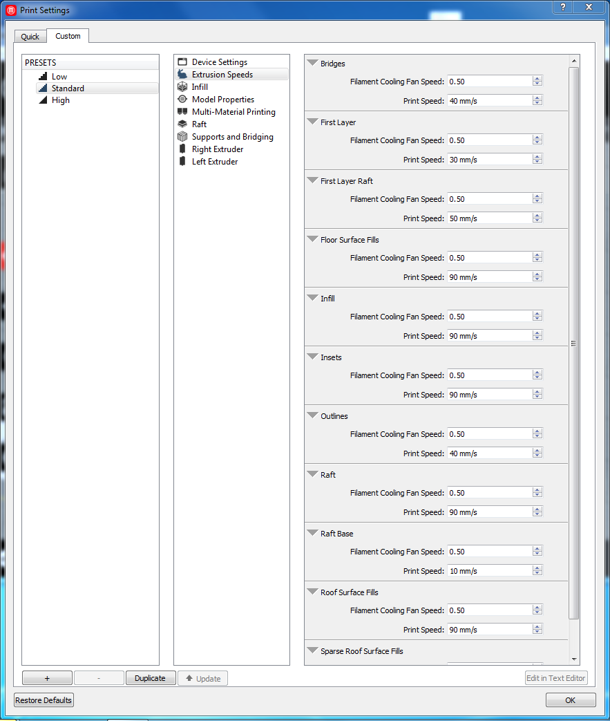
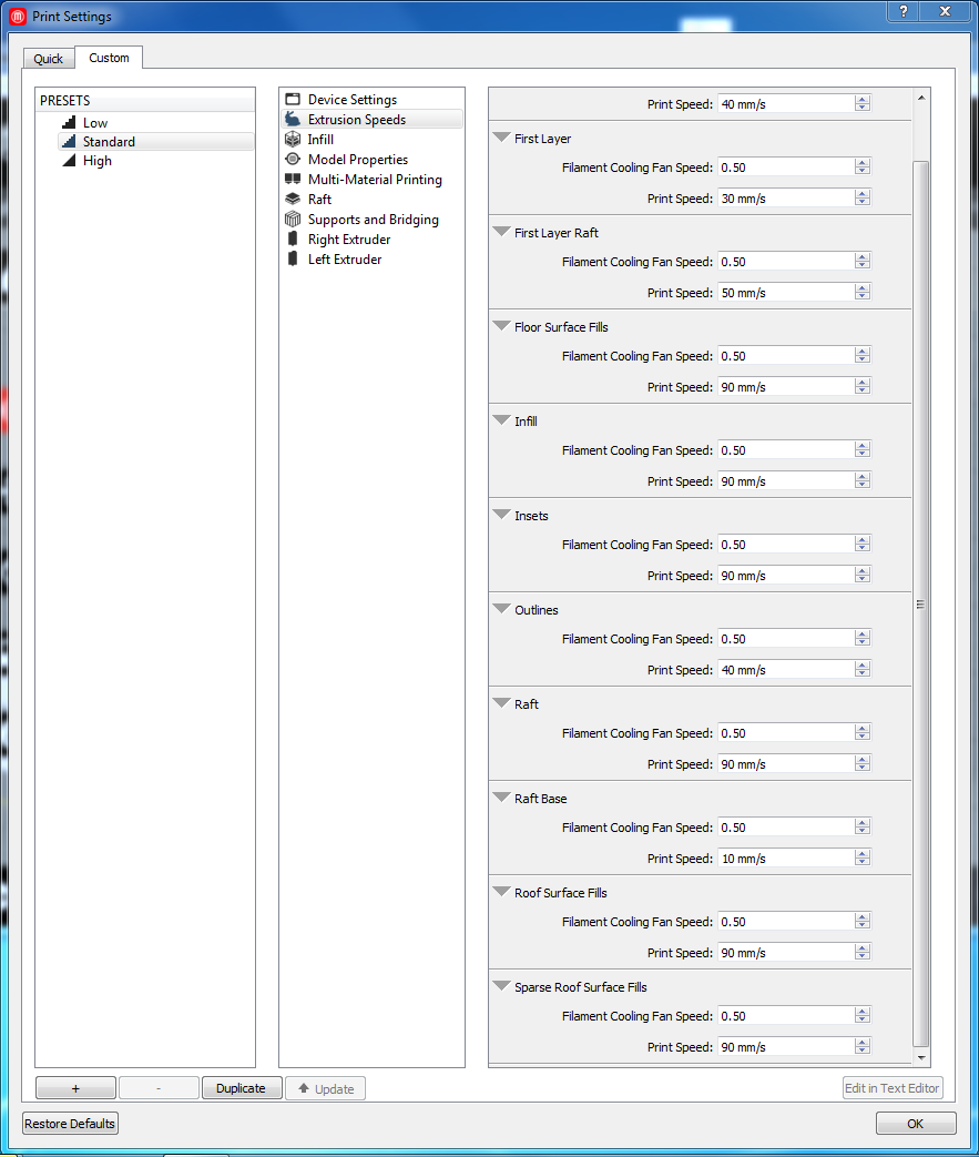
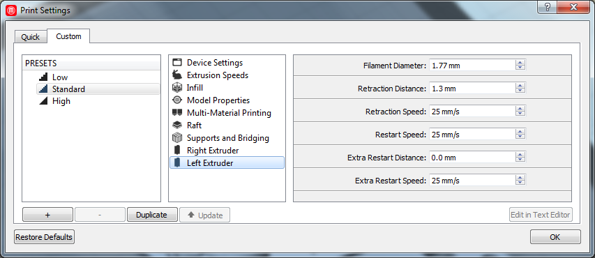
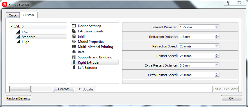
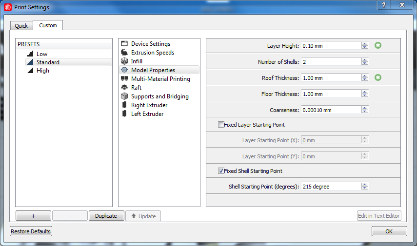
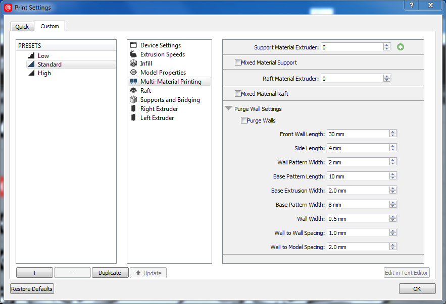
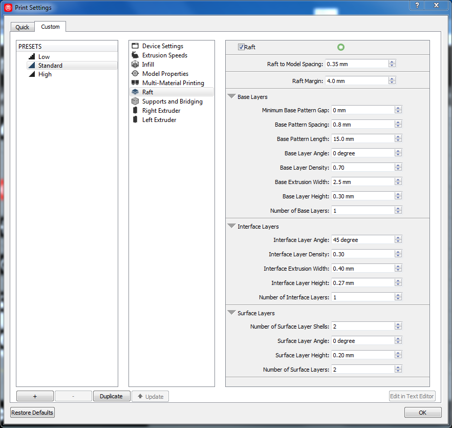
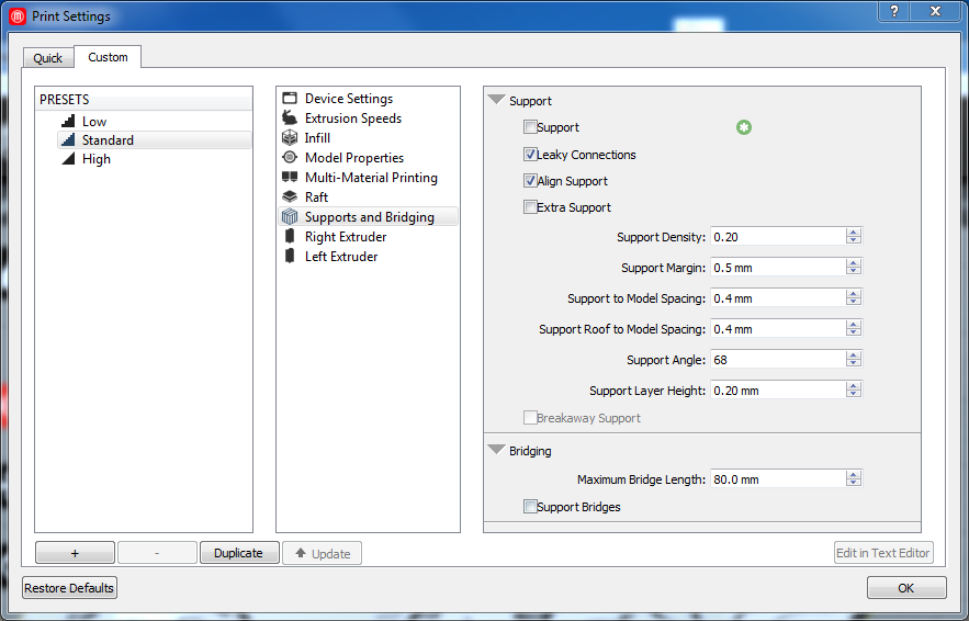
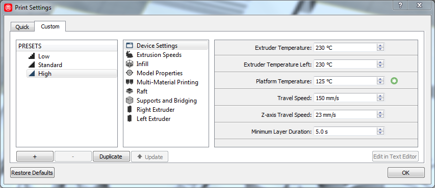
object down to one-third of its former size. For printing with the material PLA, I used following parameters:
Temperature: 230°C, Speed:70 percent, build plate temperature 60°C, layer height: 0.25 mm, shell thickness 0.8 mm,
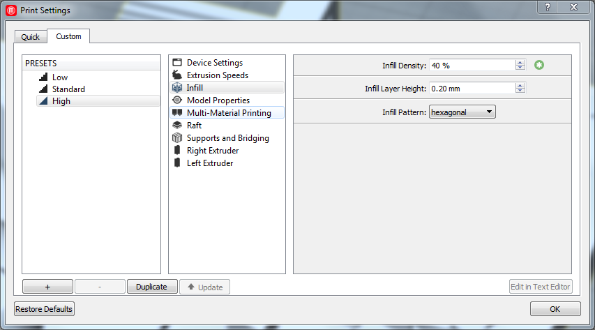
enable retraction: yes, bottom/top thickness: 0.6 mm, fill density: 15 percent, support type: everywhere, platform
adhesion type: none, nozzle size: 0.4 mm.

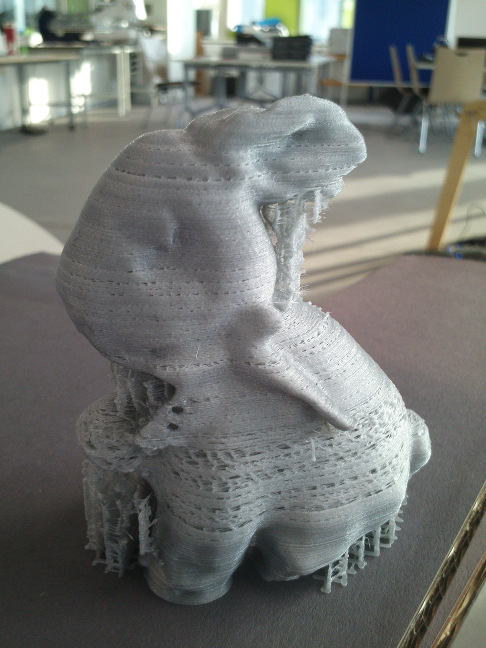
The rabbit was printed in about 2.5 hours. Its surface has not been printed correctly
on the lower part of the body. I think the printing speed, 70 percent, was too high.
For the upper part of the body, I lowered the speed to 50 percent. Now the surface was printed much denser. It turned out
that the selected speed was still too high. Apart from that, there are certain mesh regions on the surface that need editing.
Nevertheless, as my colleagues have calibrated all our printers, the result remains irritating nonetheless. Under normal
circumstances, no parameter adjustments should have been necessary. We believe that the nozzle has leavings of old filament
and require cleaning.
Design and print an object that you cannot create subtractive
This week, it was our task to design and print an 3D object that cannot be created in a subtractive way.
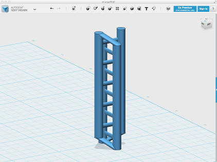
A beginner in the field of 3D construction and design, I used Autodesk's 123D Design to make a 3D object using the preset solids.
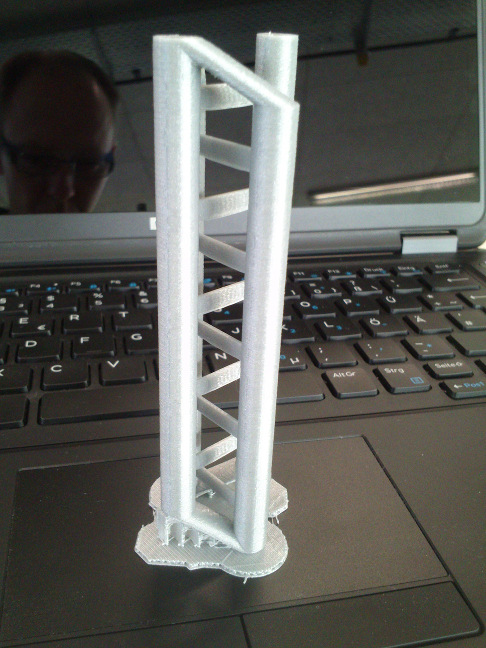
It consists of two intersecting ladders whose upper and lower legs are
interlinked (cf. fig. 10 and fig. 11). In 123D Design, I made the following steps:
- Legs of the ladder: create a cylinder primitive with a proper length and diameter, copy and paste it.
- Move the second cylinder some centimeters away from the first.
- Rungs: For the first rung, I create another cylinder with a smaller diameter, rotate it by 90 degrees.
- Select both one leg of the ladder and the rung, use Smart Align to insert the rung through the leg centered.
- If the second leg is too far away, move it nearer to the other leg.
- Copy and paste the first rung, then move the copy up the ladder. Repeat several times up and down.
- Trim the length of the legs: For the legs visible in the picture of the printed object, select both legs and use the Smart Align tool to match their lengths.
- In two succeeding steps, link the faces of a pair of legs to the third on either side of the object. As in the printed object, select the face of a leg, then of another leg and use the Loft tool to create a smooth three-dimensional progression between then.
Finally, I exported my strange object in the STL format.
I reopened the object in Cura and, as it was too delicate, scaled it up by factor 2.
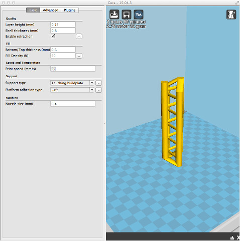
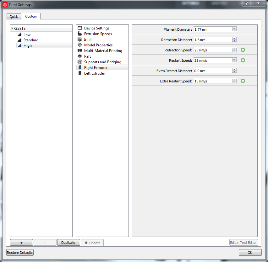
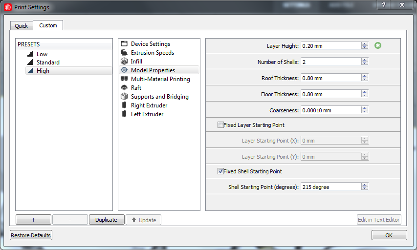
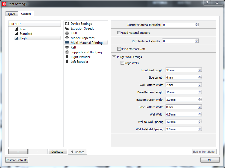
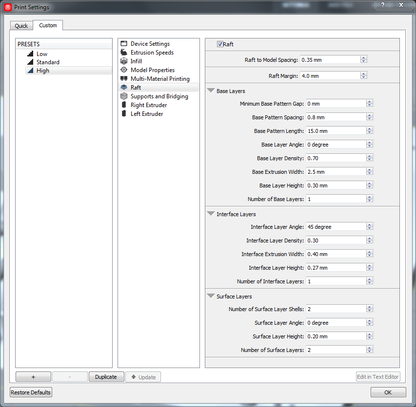
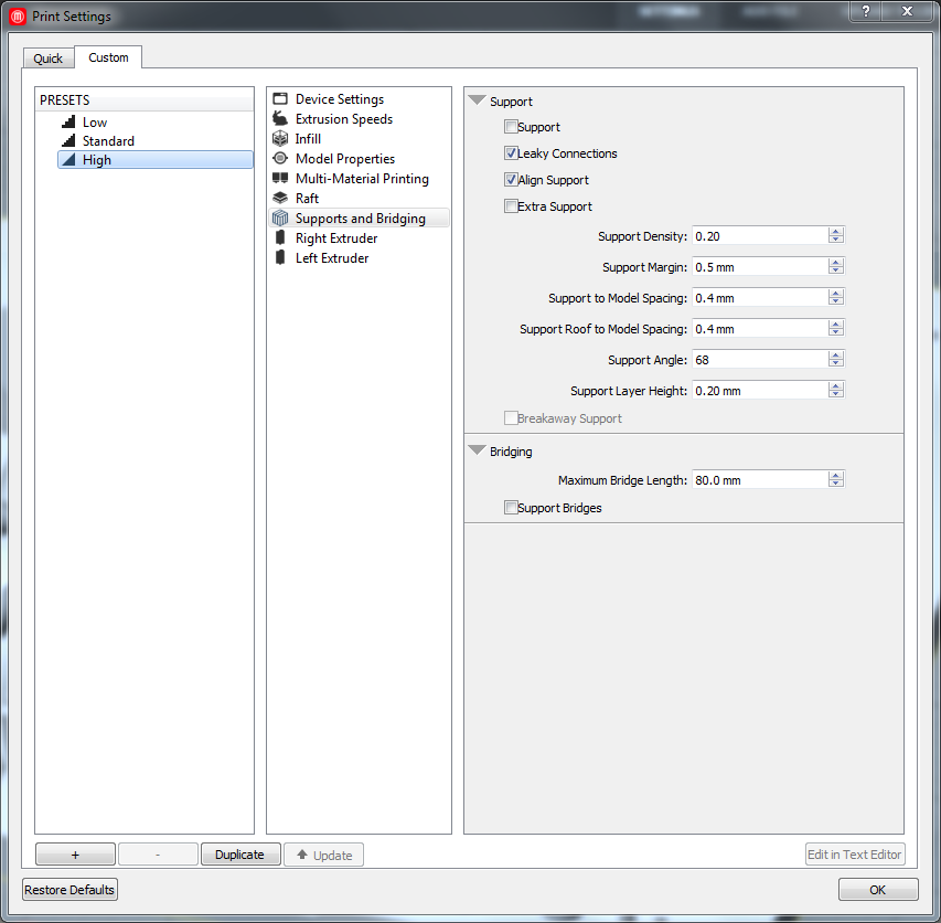
I printed it on an Ultimaker 2, using as parameters: Temperature 220°C, Speed 70 percent,
build plate temperature 60°C. For the Cura parameters, see fig. 11.
The result is shown in fig. 12. It looks decent, although not all support structures have been removed. All delicate structures, i. e.,
the rungs, have been printed correctly.
Collaborative stress test: evaluating Johnathan Yen's 3D test object for 3D printers
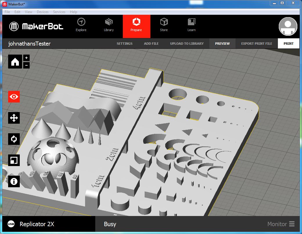
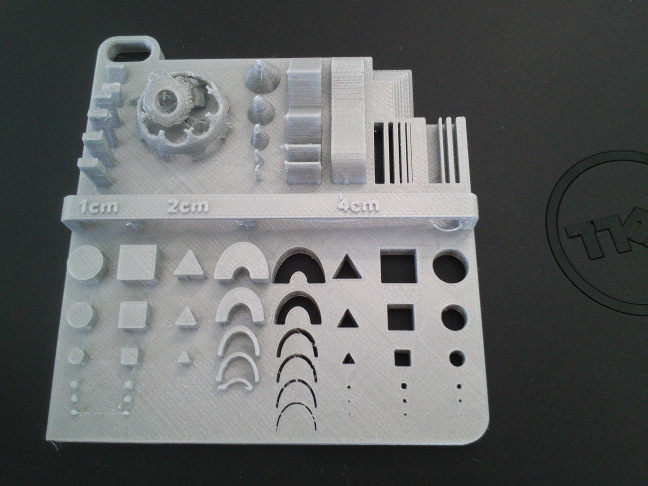
For evaluating the 3D printing capabilities of our MakerBot Replicator 2x, I let it print a test
object (get it) in STL format made by
Johnathan Yen who is also attending the FabAcademy. Fig. 13 shows the tester in the MakerBot Software.
For printing, I used the material ABS.
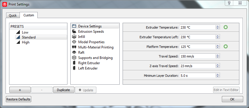
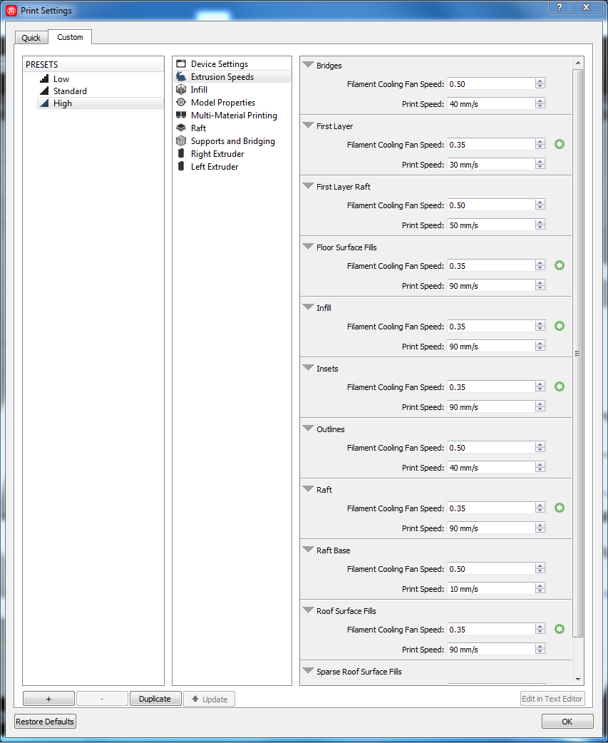
For printing, I used the parameters as detailed in below pictures (right-click to enlarge):

The first print produced nothing, as no filament came out of the nozzle. Guided by the Replicator 2X, I removed the
filament tube from the left extruder, reinserted the filament into the extruder and let it become transported down, locked the closing mechanism, then pushed the
tube back into the extruder. I did the same for the right extruder.
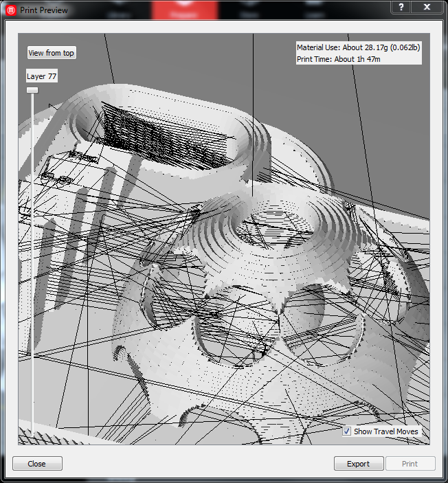
The second attempt also failed. It seems the print path got jumbled (see figs. 14 and 15), maybe due to too low a nozzle temperature, or too high a speed.
I raised it by 10°C and repeated the printing process. Printing failed again, yielding the same result.
For the next try, I changed several parameters:
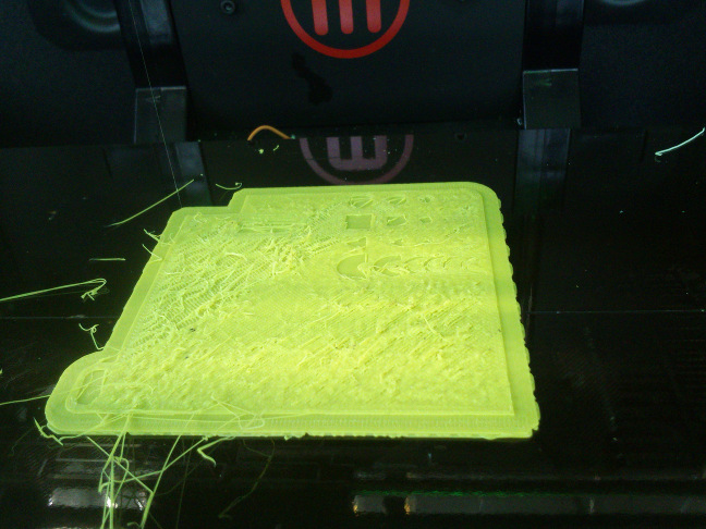
Strangely enough, the fourth try also failed. The printer reported to have finished the print after
two and a half hours, having printed only a part of the object.
In the meantime, I printed a low-poly Darth Vader from the Thingiverse repository on a Ultimaker 2 for my son.
I ended up with a Half Vader. For this object, too, the printer reported to have finished
the print halfway between. Either this is merely a strange coincidence, or I need to recapitulate my workflow.
left part of the tester was not printed correctly and therefore collapsed.
Stress testing the MakerBot Replicator 2x 3D printer
For testing, I grabbed a 3D model of a "boat" from www.thingiverse.com and
printed it on an Ultimaker 2. Oddly enough the Ultimaker 2 has only printed the plate of the boat, then messed up.
Printing the tester on the Formlabs 1X printer
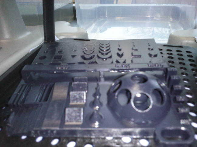
As its very first print job, we printed Johnathan Yen's tester on our FormLabs 1X 3D printer
that uses resin as material. For a Desktop printer, we found the result amazing (see fig. 18).
Lessons learned
- It may take several tries until a 3D print is satisfying.
- The Replicator 2X printer is harder to use than, i. e., a Ultimaker 2. The latter can be tweaked during the printing process.
- Inferring a geometry with a Photogrammetry approach requires a lot of photographs.
- Neil: Extruders and PLA have a lifetime. Ultimaker 2 prints should be gorgeous.
- Neil: To go slow on a printer is not always better than to go fast. It depends on the printer.
Source files
Rabbit in PLY format: hereRabbit in STL format: here
Rabbit in OBJ format: here
Photographs of the Rabbit: here
VisualSFM Dense Reconstruction of the Rabbit: here
VisualSFM reconstruction of the Arc de Triomphe front: here
My object that cannot be done subtractive: here
Johnathan Yen's 3D printer tester object: here