E15: Networking and Communications
This weeks assignment deals with the communcation of different boards (i.e. processors)
-
Assignment:
- Design and build a wired &/or wireless network connecting at least two processors Software:
- Arduino IDE Results:
How to MAKE it
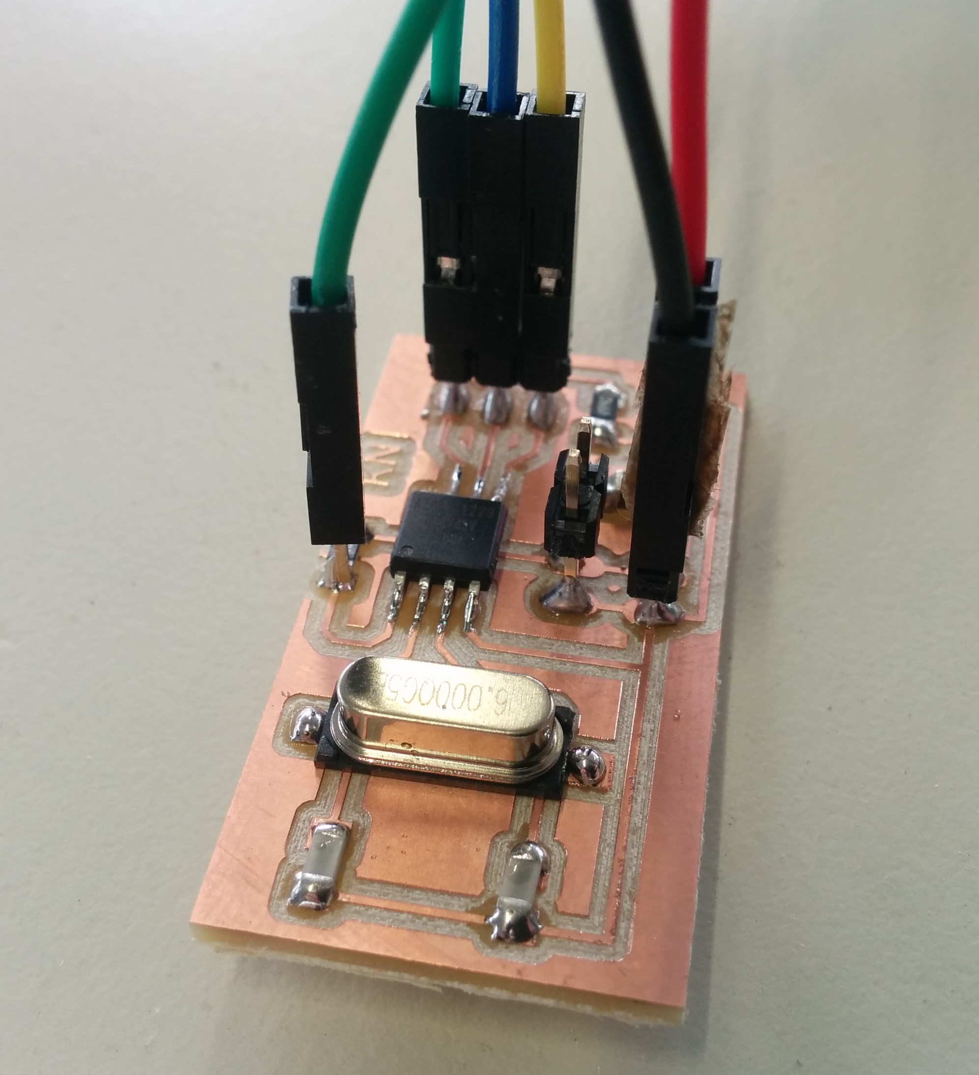
For this assignment I decided to make a network consisting of three different boards. As I already did something with Serial, as you can read below in EXTRA of this page, I wanted to experiment with I2C and to implement a really simple communication system based on reading the digital output of a pin from another microcontroller.As a the first board I used the board I made for output devices assignment, the modified satshakit:
This board will act a I2C master and will control one of the other boards. As other other boards I made two identical little boards, made by modifying the ACDInput board I did for input devices assignment. I removed anything unnecessary from the board to have a minimalistic layout for networking purpose.
Here are the main features of this little board:
- uses the Attiny45 microcontroller
- has one more vcc and gnd pins
- has a LED as output device
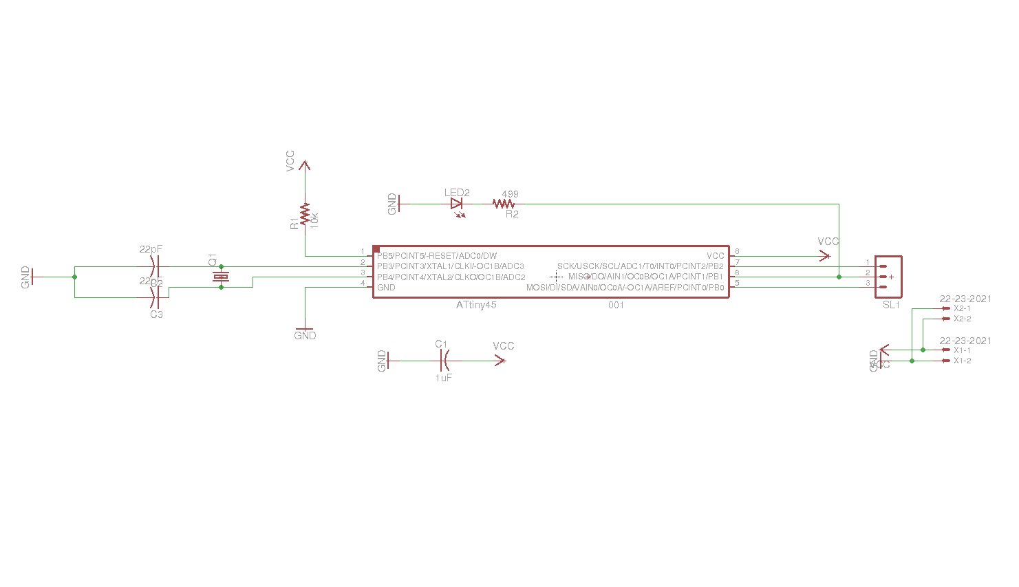
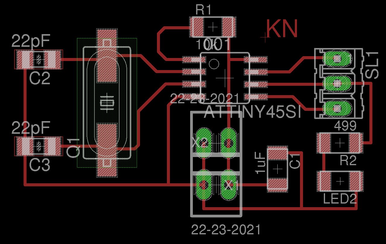
Here you can have look on the new schematic:
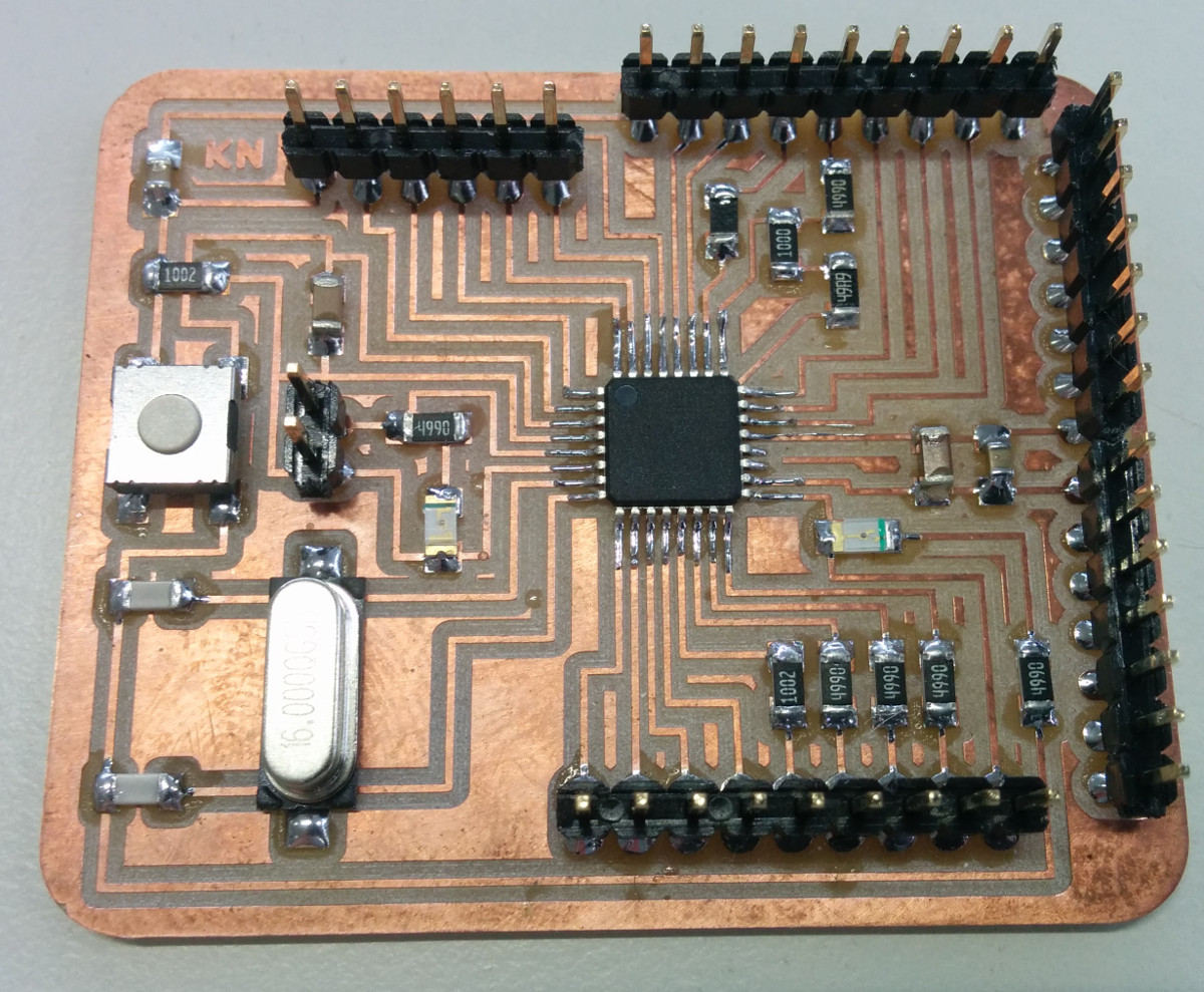
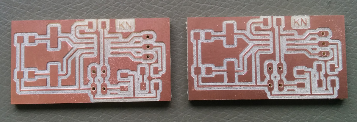
And here is the new board layout. The three pins on the right are MISO, MOSI and SCK for programming:
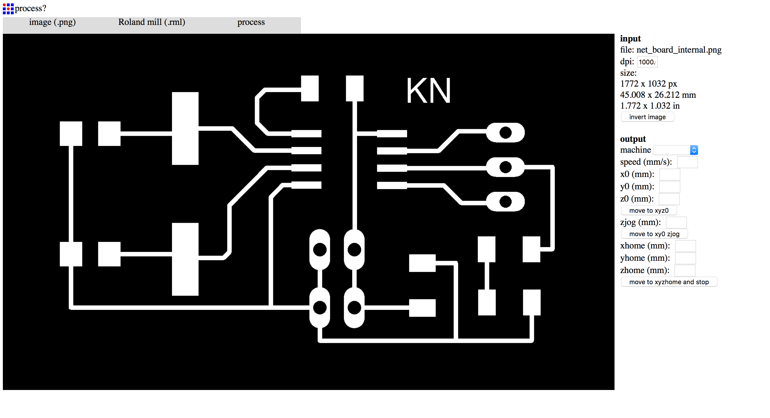
As the output device assignement I used again out local installation of the FabModules with our Roland MDX40A.
As the boards are small and fast to mill also here I added 8 offsets to have a better spacing between the copper.
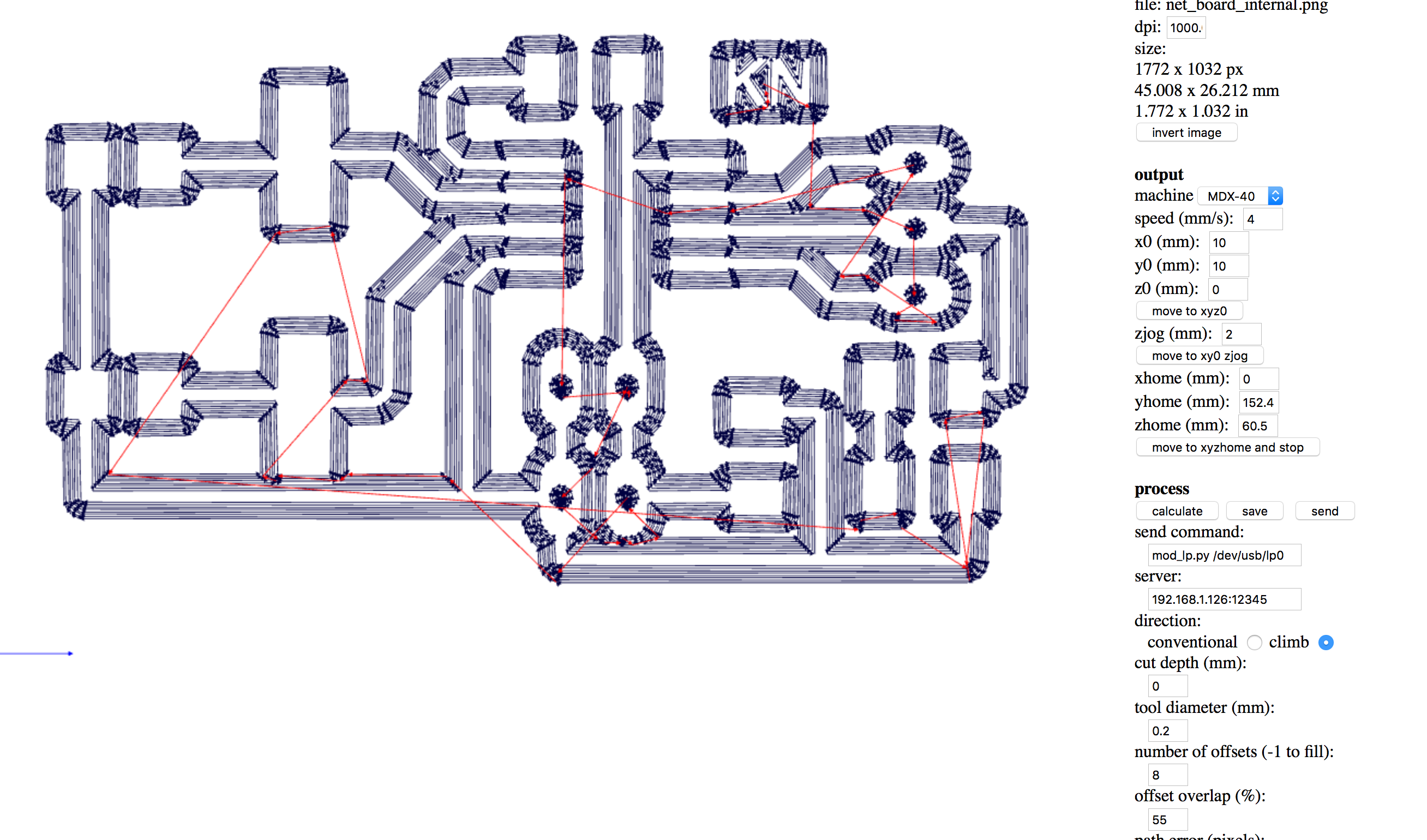
To save time, I decided to mill the board one near the other, in two different jobs but without changing the tool and doing all together the engraving. Then, after chainging the tool, I did the in the same way the cuts.
Here are the tools I used:
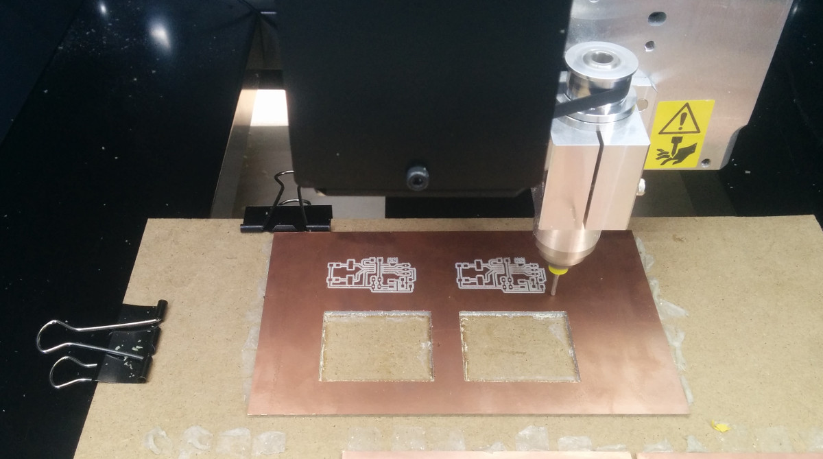
As you can see the milling process was ok and the boards were ready to be soldered:
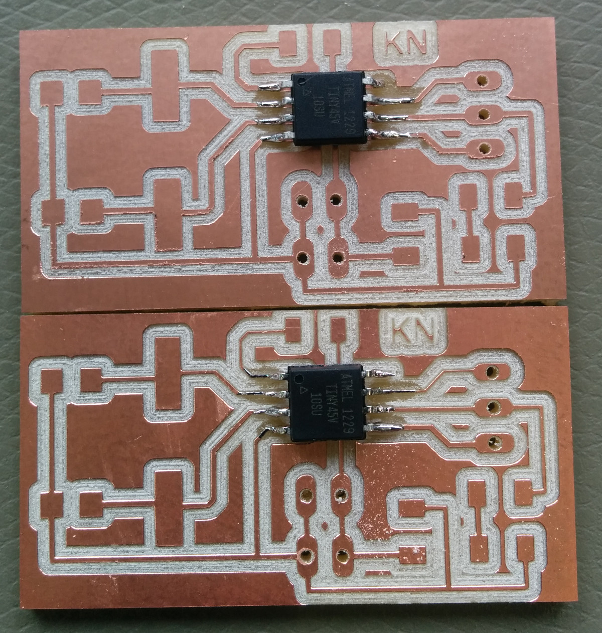
After having soldred the boards, I discover that I forgot to put the reset pin and...no problem! I soldered on the fly two pins near the 10K resistor of the Attiny45 reset pin:
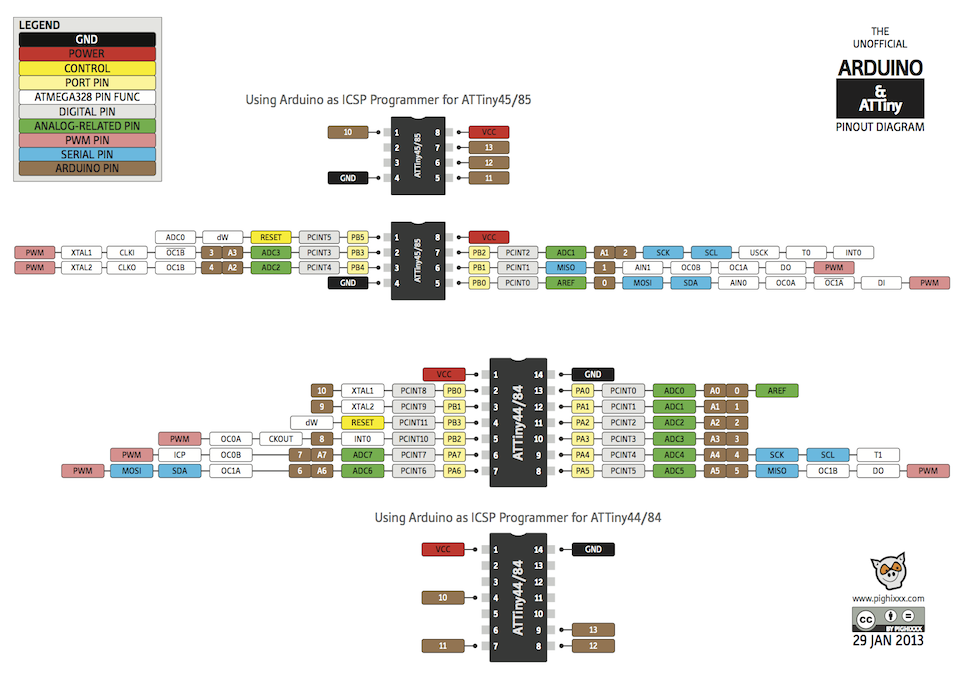
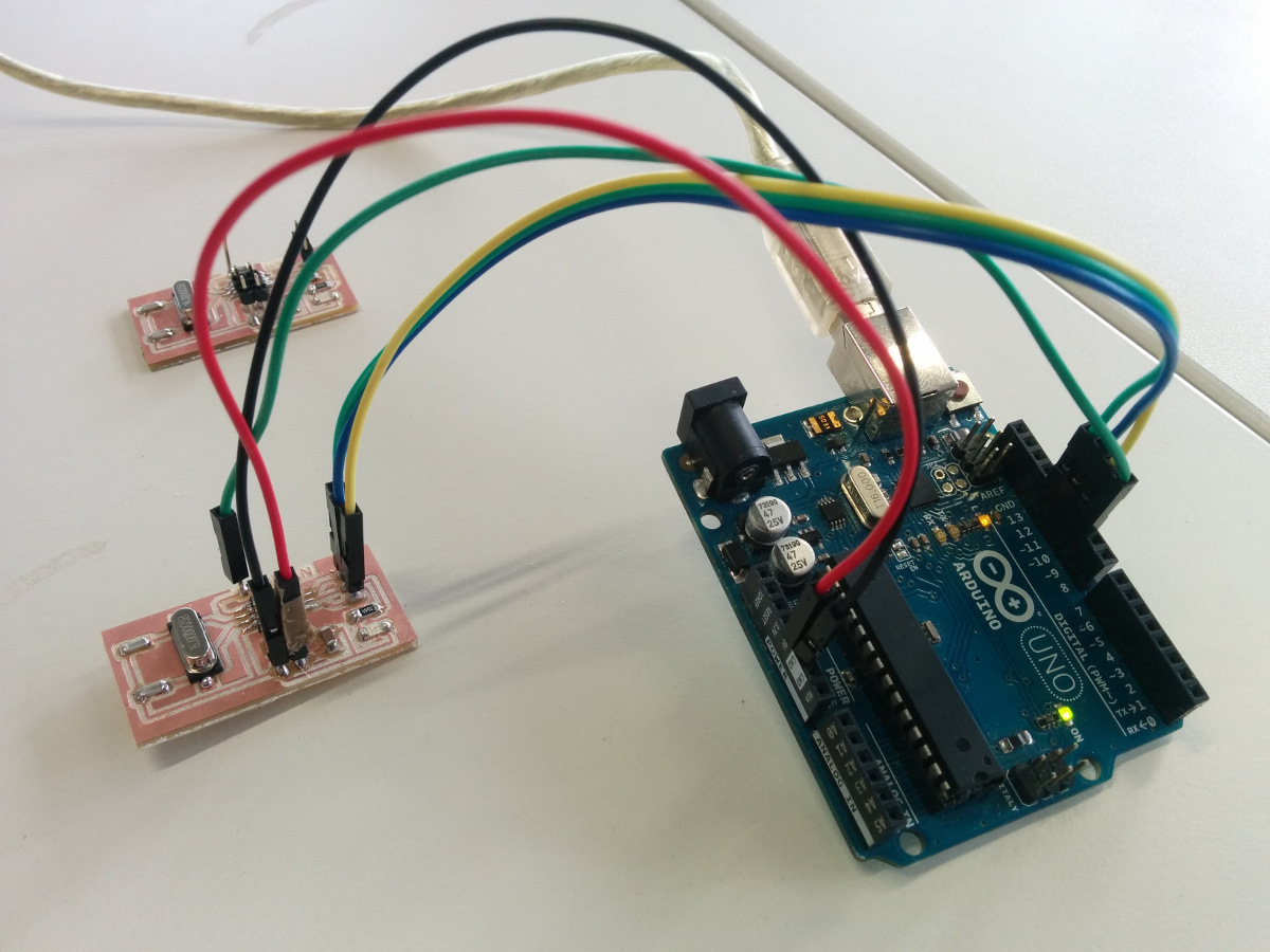
To program the board I used an Arduino a ISP and patched my Arduino IDE with the library that brings the compatibility with the little Attiny microcontrollers by David A. Mellis: Programming an ATtiny w/ Arduino 1.6 (or 1.0). I connected the little board with the Arduino as shown in the following pictures.
First of all I burnt the bootloader, to be able to set the correct Fuses on the microcontroller. And then I tried to upload of both board the blink examples, to further proof if they were working:
As the Attiny microcontroller have really limited resources is not possible to directly use the Wire.h Arduino library to use I2C. Instead I found the tutorial about I2C (master and slave) on the ATtiny85 which uses the TinyWire Slave Library and the TinyWire Master Library. As is written in the tutorial, for masters having different frequency you need to modifiy the header of the library, but is not explained how. So I just used the TinyWire Slave library on one of the boards and used the Wire.h to implement a master on the modified satshakit.
Code time!
Here is all the code I implemented for this assignent, which consist of:
- the code using Wire.h for the modified satshakit master
- the code using the TinyWire Slave library for one of the little boards
- the code that will read a digital input in the other small board
Here is the code for the master:
//code of the master modified satshakit
#include<Wire.h>

bool byteSend;

void setup() {

Wire.begin();
pinMode(13,OUTPUT);

byteSend = false;

}

void loop() {

Wire.beginTransmission(55);

if(!byteSend){

  Wire.write(100);
  byteSend = true;
  digitalWrite(13,LOW);

}else
if(byteSend){

  Wire.write(200);
  byteSend = false;
  digitalWrite(13,HIGH);

}

Wire.endTransmission();

delay(1000);


}
Here is the code of the slave:
//code of the Attiny45 slave
#include<TinyWireS.h>

byte bufferByte;

void setup() {

TinyWireS.begin(55);
pinMode(1,OUTPUT);
digitalWrite(1,LOW);

}

void loop() {

if(TinyWireS.available() > 0){

   bufferByte = TinyWireS.receive();

   if(bufferByte == 100){
    digitalWrite(1,HIGH);
   }else
  if(bufferByte == 200){

    digitalWrite(1,LOW);


  }

  }

}
And finally here is the code of the little board reading the digital input:
//code of the digital endpoint
void setup() {

  pinMode(2,INPUT);
  pinMode(1,OUTPUT);
  digitalWrite(1,LOW);

}

void loop() {


  if(digitalRead(2) == HIGH)
    digitalWrite(1,LOW);
  else
    digitalWrite(1,HIGH);

}
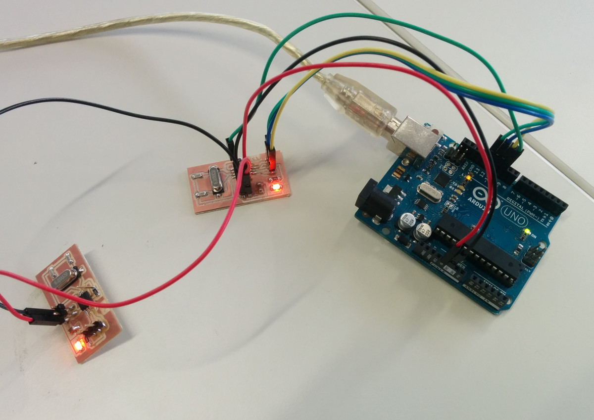
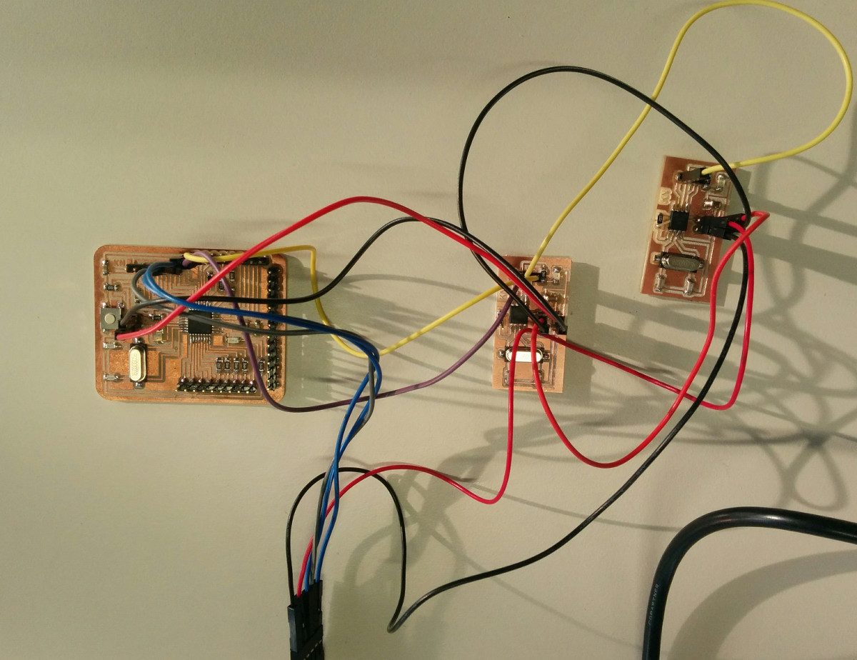
Here you can see the final connections of the complete setup of the three boards. Note that between the satshakit and the first little board I have connected SDA and SCL for the I2C, and that from the first little board to the last there is only one pin connected for the digital input. Of course the ground is shared among all of the boards.
Finally here is the video about of the successfull working synchronized & networked blink:
Downloads
EXTRA
During week 11 assignment of E11: Input Devices I already dealt with the communication between the satshakit and my ADCInputBoard. Following paragraphs are quotes of that assignment.The attiny45 does not have "real" searial communication. It is not full-duplex. You can read from RX (PB2). Neil implemented a software-serial communication that works with 9600 baud (see neils code on Input Devices).
So, Neils board has low-boud-rate serial OUTPUT communication.
If you want to use the serial library of the Arduino, you need to implement software-serial communication.
We checked if flashing the 45 enables soft serial communication. It does. But it will be slow: >9600 baud max if you use c code or >4800 baud max if you want to use the arduino serial communication. (The attiny85 would be able to work on 9600 baud max)
Benefits of serial communication:
- Software serial can be used when you have different voltages of differnt boards, communication with each other.
- You do not necessarily need an external clock.
Thats why I modified the board and added wired RTX to the FTDI connector, for initialization and later use of the Arduino serial communication library. Later, this still will be software-based serial communication but works under the hood and feels like typical serial communication (in the arduino environment).
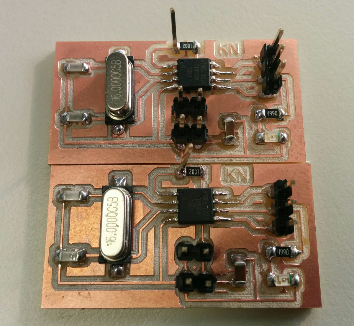
For stable measurements and communication I added a crystal (16Mhz) to the board.
I also wanted to have full duplex communication in my final design for the final project (for safety reasons).
In principle I understand that one can scale down the board according to constraints (e.g. power consumption, board size, etc.) but in my scenario I don't need this.
I did some simple calculations about the speed and the requiremed baud rate to determine if the attiny45 fulfils my requirements.
I assumed a maximum speed of 10 km/h that I want to drive with the fabKickBoardmax. 10km/h = 10.000m / 3600s = 2.777m/s Im my setting: 2,7777m/s / 0.11m = 24.54 rotations per second ADC3 has a 10-Bit resolution So I have to send 2 Bytes * 25 = 50 Bytes per second (for 10km/h). A baudrate of 9600 is capabe of 9600/8 = 1200 bytes per second. So, the attiny44 will fulfill my requirements....
Programming the board
Because my board has no hardware serial communication I have to use software serial communication.
- Open Arduino IDE.
- Load ArduinoISP from examples.
- Connect Arduino via USB to computer.
- Upload ArduinoISP to the board.
- Connected the Arduino to the ADCIputBoard. Pins MOSI, MISO and SCK are digital pin 11, 12 and 13. RST is pin 10.
- Burn the bootloader to the board.
- Write code you want to upload to the ADCInputBoard ...
Also, I want to use Arduino standard libraries for serial comunication. So I have to map the pins according to this scheme:
Following are the mappings in the code:
        // set RX TX for serial communicaton

        const byte rxPin = 1; // RXD = PB1 = 1

        const byte txPin = 0; // TXD = PB0 = 0


        // set up a new software serial object

        SoftwareSerial mySerial ( rxPin, txPin);
To read analoug input I have to map the pin, too.
       // to read from ADC

        int inputPin = A1; // PB2
As I use SCK as SHARED PIN .... remove SCK from ISP header of the ADCIputBoard (because it is used as shared pin with PB2 to read analog input)
- Then connect ADC, GND and VCC from ADCIputBoard
- Choose AtTiny from Tools->Board in the Arduino IDE.
- Choose sketch you want to upload.
- Choose Sketch->Upload Using Programmer.
Connect FTDI Cable and open serial monitor. Select the baudrate of 4800.
If you face problems with serial ouput, such as strange characters, first try to changed RX with TX or check the baud rate.
Finally, I still did not recieve all mySerial.print() outputs. It is an indcator for to much output. Thus, I reduced debugging outputs to a minimum and finally, it worked.
/*
 *  AUTHOR: Rob van den Tillaart; modified Ralph Martin; modified by Karsten Nebe
 *    DATE: 2016-05-30
 *     ORIGINAL URL: http://playground.arduino.cc/Code/HallEffect
 *
 * PURPOSE: use an A1301 or A1302 as magnetometer
 *
 * Pin Layout LH Package
 * =====================
 *  1     VCC 5V
 *  2     signal    connected to Analog 0
 *  3     GND
 *
 * Pin Layout UA Package
 * =====================
 *  1     VCC 5V
 *  2     GND
 *  3     signal    connected to Analog 0
 *
 */

#include <SoftwareSerial.h> // we need to establish software serial communication

#define NOFIELD 505L    // Analog output with no applied field, calibrate this


// check this link for mapping of Arduino and AtTiny45 pins http://orig06.deviantart.net/82c9/f/2013/038/3/7/attiny_web_by_pighixxx-d5u4aur.png

// set RX TX for serial communicaton
const byte rxPin = 1; // RXD = PB1 = 1
const byte txPin = 0; // TXD = PB0 = 0

// set up a new software serial object
SoftwareSerial mySerial ( rxPin, txPin);


// to read from ADC from pin 7 of the AtTiny (PB2)
int inputPin = A1; // PB2


long compensated;
long gauss;
int raw;


// Uncomment one of the lines below according to device in use A1301 or A1302
// This is used to convert the analog voltage reading to milliGauss
//#define TOMILLIGAUSS 1953L  // For A1301: 2.5mV = 1Gauss, and 1024 analog steps = 5V, so 1 step = 1953mG
#define TOMILLIGAUSS 3756L  // For A1302: 1.3mV = 1Gauss, and 1024 analog steps = 5V, so 1 step = 3756mG

void setup()
{
    mySerial.begin(4800);

}

void DoMeasurement()
{
// measure magnetic field
  raw = analogRead( inputPin );   // Range : 0..1024

  mySerial.println(raw);

  compensated = raw - NOFIELD;                 // adjust relative to no applied field
  gauss = compensated * TOMILLIGAUSS / 1000;   // adjust scale to Gauss


 /*
  mySerial.println(gauss);

  if (gauss > 0)     mySerial.println("(S)");
  else if(gauss < 0) mySerial.println("(N)");
  else               mySerial.println("*");
*/

  if(raw > 800) raw = 800;
  else if(raw < 200) raw = 200;

}

void loop()
{
    delay(10);
    DoMeasurement();
}