
E08: Embedded Programming
This week is about embedded programming. We are supposed to program our Hello World Board in as many ways as possible.
I used the Arduino IDE and command line (gcc). I also made several versions of programs to compare the efficiency of the different environments.
-
Assignment:
- 1: read a datasheet of a microcontroller
- 2: program your board to do something, with as many different programming languages and programming environments as possible; Make the board to send a message to the computer and vice verca; See how many ways of programming you can do.
- For extra credit: try another processor family Machines/Tools:
- Arduino UNO
- FabISP
- Hello World Board Software:
- Gcc, AVR
- Arduino IDE
- xCode
Notes from lecture + comments:
- We are using a harvard architecture. We are gonna be using a risk controller.
- We are using AVR. I tis also the processor on the Arduino.
- They are designed for modern compile tools.
- In AVR everything is handled in one cycle (single cycle instructions).
- There is a realtion of the power and clock speed.
- GCC is compiler that works across many architectures; ARVs are designed with GCC in mind.
- There are 2 versions of USB 2 Serial cables. The problem wih the 3.3 volts cable is, that VCC supplies not 3.3 volts but 5V - which will kill your board if it is jsut designed for 3.3V
- If you want to program your AVR using the Arduino IDE, check this: http://highlowtech.org/?p=1695
Links:
http://publications.gbdirect.co.uk/c_book/
using the arduino as programmer
Programming Digital Outputs on Atmel AVR Microcontroller’s | A beginner’s guide
Read the Datasheet
I found useful to overlap comments directly onto the original datasheet.
Here you can see my commented datasheet I have used to figure out about the microcontroller we have to use for this assigment:
Here is the link to download the commented datasheet.
How to MAKE your board doing something
I faced difficulties to program my Hello World Board (HWB).
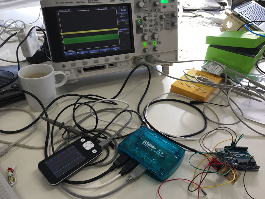
In order to eliminate problems in the tool-chain I wanted to test whether I can program my HWB by using an Arduino by following this instruction:
AVR-Programming-with-Arduino-AVRdude-and-AVR-gcc
However, I had to connect the board differently than in the first-step picture of the instructions.
Arduino->HWB
12->MISO (1)
13->SCK (2)
10->RESET (3)
VCC->VCC (4)
11->MOSI (5)
GND->GND (6)
In the tutorial above they use the ATTiny85 but I am using the 44. Thats Why I had to change the line of code as follows:
avrdude -c arduino -p attiny45 -P /dev/tty.usbmodemfd121 -U flash:w:led_flash.hex
However, it did not work. I still received the rc -1 error message.
Once again I started testing my board.
It turned out that I had a short circuit on my board. Systematically I tried to eliminate by desoldering each component and testing connections. At the end it was a bridge between a resonator and capacitor. Unfortunately I figured this out after I had removed almost all components :)
Thus, finally I re-soldered all components.
Then I tried to program it ... again.
Using the Arduino IDE to progam the HWB
I still wanted to test it with the Arduino because I did not knew whether my ISP works. This time I also wanted to use the Arduino IDE, by following these instructions on High-Low Tech Group :: MIT Media Lab
Learnings (so far):
- If you want to program your HWB using the Arduino you have to burn the bootloader. Only then, the HWB can handle the programming language used in Arduino IDE.
- You do not need to connect booth, the Arduino via USB and the HWB via USB.
However, if you to attach booth, make sure you cut the power suppy (VCC connection) from the Arduino to the HWB. It may cause damage to you computer. - Better always use an active USB-HUB.
- Dont forget to burn the boatloader before uploading your "Arduino code"
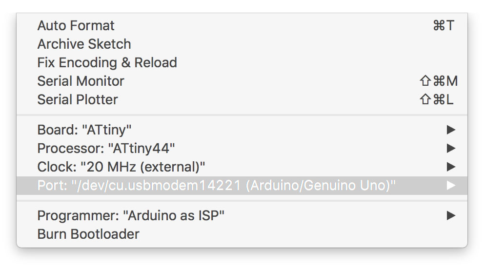
- These are the settings you need to make for the Arduino as ISP
There was another issue: My Mac did not show any serial port in the Arduino IDE. After some research it turned out that this seemed to be a "common" problem in El Capitan.
I used these Winchiphead CH340 serial bridge driver: http://blog.sengotta.net/signed-mac-os-driver-for-winchiphead-ch340-serial-bridge/ and they work fine.
MAKE a blink example (a simple one and one with better performance)
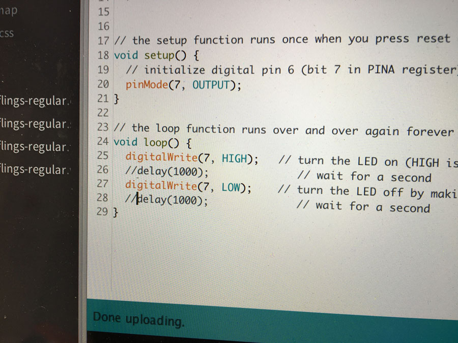
I made a simple blink example, which is a modified version of the standard blink example that comes with the Arduino IDE. The important difference is, that the digital pin 6 to which I have connected the LED on my HWB needs to be adressed as bit 7 in accordance to the PINA register.
/*
BlinkArdunio example for the Hello World Board of the FabAcademy assignment

Turns on an LED on for one second, then off for one second, repeatedly.

The LED is attached to digital pin 6 (bit 7 in PINA register)


Karsten Nebe
*/


// the setup function runs once when you press reset or power the board
void setup() {
// initialize digital pin 6 (bit 7 in PINA register) as an output.
pinMode(7, OUTPUT);
}

// the loop function runs over and over again forever

void loop() {

    digitalWrite(7, HIGH);   // turn the LED on (HIGH is the voltage level)
    delay(1000);              // wait for a second
    digitalWrite(7, LOW);    // turn the LED off by making the voltage LOW
    delay(1000);              // wait for a second
}
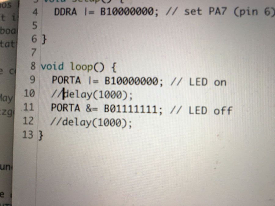
Yet another blink example - but more efficient
Next is another example tat does the same. However, instead of using the digitalWrite() I directly manipulated the registers.
/*
BlinkBasic is a more rudimentary example for the Hello World Board
It turns on an LED on for one second, then off for one second, repeatedly.
The LED is attached to digital pin 6 (bit 7 in PINA register)
Here, no "digitalWrite()" command has been used.

Karsten Nebe
*/

void setup() {
DDRA |= B10000000; // set PA7 (pin 6) as output
}

void loop() {
    PORTA |= B10000000; // LED on (bitwise logical OR)
    delay(1000);
    PORTA &= B01111111; // LED off (bitwise logical AND)
    delay(1000);
}
Comparison


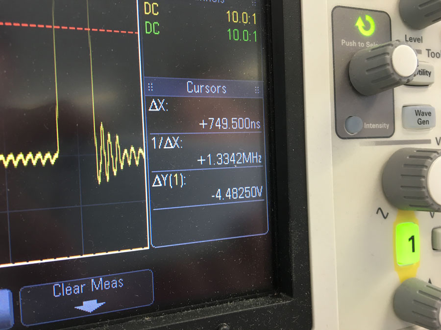
The same operation can be done by bitwise operations (here: OR and AND). The difference in speed is increddible. Booth operations (enable and disable a port) takes 749ns = 0,75us (1,33Mhz).
Using the command line to progam the HWB
If you want to program your HWB using the arduino, then you have to apply these commands:
make
make program-arduino-fuses
sudo make program-arduino
You also need to modify your Makefile by adding the following lines, whereas "/dev/ttyACM0" represents the port your Arduino is attached to. Thus, you may need to edit it accordingly (You can use the Arduino IDE menue Tools, to check for it. In my case it used to be "/dev/cu.usbmodem14221"
    program-arduino: $(PROJECT).hex
    avrdude -p t44 -b19200 -P /dev/ttyACM0 -c stk500v1 -U flash:w:$(PROJECT).c.hex

    program-arduino-fuses: $(PROJECT).hex
    avrdude -p t44 -b19200 -P /dev/ttyACM0 -c stk500v1 -U lfuse:w:0x5E:m
If you want to use your FabISP, you have to use thesse commands:makemake program-usbtiny-fusessudo make program-usbtiny
// LED Button Blink Program
// Karsten Nebe
#include <avr/io.h>
#define F_CPU 1e6
#include <avr/delay.h>

#define TRUE 1
#define FALSE 0

int main()
{
//SETUP
//Button is on PB2
//LED is PA7

PORTB = _BV(PB2); //Turn button pullup resistor on (value)
DDRA  = _BV(PA7); //Enable output on the LED pin (0= input; 1=output)
//PORTA = _BV(PA7); //Turns LED on (value)

//LOOP
while (TRUE)
{

    if ((PINB & _BV(PB2))) //button is not pushed
        {
        PORTA |= _BV(PA7); //turn LED on (bitwise OR)
        _delay_ms(1000);
        PORTA &= _BV(!PA7); //turn LED off (bitwise AND)
        _delay_ms(1000);

        }
    else
    {
        //PORTB= _BV(PB2); //Turn button pullup resistor on
    }
}

}
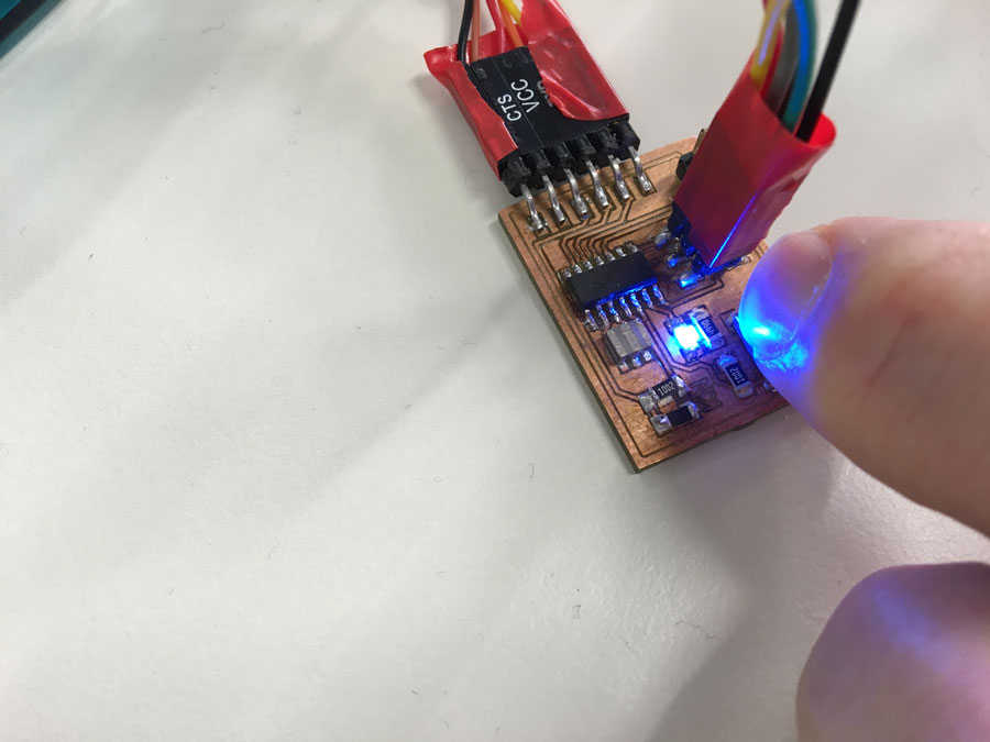
Finally - the HWB works :)
Download
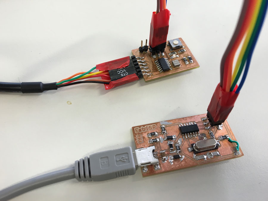
Program the HWB using the FabISP
Connect the FabISP and the HWB to your USB-Hub. Also connect the FabISP and the HWB using your FTDI cable. Then connect your USB-Hub to your computer.
Upload an Echo-Example program
For the echo example I used Neil's program hello.ftdi.44.echo.c and the corresponding Makefile.
//
//
// hello.ftdi.44.echo.c
//
// 115200 baud FTDI character echo, with flash string
//
// set lfuse to 0x5E for 20 MHz xtal
//
// Neil Gershenfeld
// 12/8/10
//
// (c) Massachusetts Institute of Technology 2010
// This work may be reproduced, modified, distributed,
// performed, and displayed for any purpose. Copyright is
// retained and must be preserved. The work is provided
// as is; no warranty is provided, and users accept all
// liability.
//

#include <avr/io.h>
#include <util/delay.h>
#include <avr/pgmspace.h>

#define output(directions,pin) (directions |= pin) // set port direction for output
#define set(port,pin) (port |= pin) // set port pin
#define clear(port,pin) (port &= (~pin)) // clear port pin
#define pin_test(pins,pin) (pins & pin) // test for port pin
#define bit_test(byte,bit) (byte & (1 << bit)) // test for bit set
#define bit_delay_time 8.5 // bit delay for 115200 with overhead
#define bit_delay() _delay_us(bit_delay_time) // RS232 bit delay
#define half_bit_delay() _delay_us(bit_delay_time/2) // RS232 half bit delay
#define char_delay() _delay_ms(10) // char delay

#define serial_port PORTA
#define serial_direction DDRA
#define serial_pins PINA
#define serial_pin_in (1 << PA0)
#define serial_pin_out (1 << PA1)

#define max_buffer 25

void get_char(volatile unsigned char *pins, unsigned char pin, char *rxbyte) {
   //
   // read character into rxbyte on pins pin
   //    assumes line driver (inverts bits)
   //
   *rxbyte = 0;
   while (pin_test(*pins,pin))
      //
      // wait for start bit
      //
      ;
   //
   // delay to middle of first data bit
   //
   half_bit_delay();
   bit_delay();
   //
   // unrolled loop to read data bits
   //
   if pin_test(*pins,pin)
      *rxbyte |= (1 << 0);
   else
      *rxbyte |= (0 << 0);
   bit_delay();
   if pin_test(*pins,pin)
      *rxbyte |= (1 << 1);
   else
      *rxbyte |= (0 << 1);
   bit_delay();
   if pin_test(*pins,pin)
      *rxbyte |= (1 << 2);
   else
      *rxbyte |= (0 << 2);
   bit_delay();
   if pin_test(*pins,pin)
      *rxbyte |= (1 << 3);
   else
      *rxbyte |= (0 << 3);
   bit_delay();
   if pin_test(*pins,pin)
      *rxbyte |= (1 << 4);
   else
      *rxbyte |= (0 << 4);
   bit_delay();
   if pin_test(*pins,pin)
      *rxbyte |= (1 << 5);
   else
      *rxbyte |= (0 << 5);
   bit_delay();
   if pin_test(*pins,pin)
      *rxbyte |= (1 << 6);
   else
      *rxbyte |= (0 << 6);
   bit_delay();
   if pin_test(*pins,pin)
      *rxbyte |= (1 << 7);
   else
      *rxbyte |= (0 << 7);
   //
   // wait for stop bit
   //
   bit_delay();
   half_bit_delay();
   }

void put_char(volatile unsigned char *port, unsigned char pin, char txchar) {
   //
   // send character in txchar on port pin
   //    assumes line driver (inverts bits)
   //
   // start bit
   //
   clear(*port,pin);
   bit_delay();
   //
   // unrolled loop to write data bits
   //
   if bit_test(txchar,0)
      set(*port,pin);
   else
      clear(*port,pin);
   bit_delay();
   if bit_test(txchar,1)
      set(*port,pin);
   else
      clear(*port,pin);
   bit_delay();
   if bit_test(txchar,2)
      set(*port,pin);
   else
      clear(*port,pin);
   bit_delay();
   if bit_test(txchar,3)
      set(*port,pin);
   else
      clear(*port,pin);
   bit_delay();
   if bit_test(txchar,4)
      set(*port,pin);
   else
      clear(*port,pin);
   bit_delay();
   if bit_test(txchar,5)
      set(*port,pin);
   else
      clear(*port,pin);
   bit_delay();
   if bit_test(txchar,6)
      set(*port,pin);
   else
      clear(*port,pin);
   bit_delay();
   if bit_test(txchar,7)
      set(*port,pin);
   else
      clear(*port,pin);
   bit_delay();
   //
   // stop bit
   //
   set(*port,pin);
   bit_delay();
   //
   // char delay
   //
   bit_delay();
   }

void put_string(volatile unsigned char *port, unsigned char pin, char *str) {
   //
   // print a null-terminated string
   //
   static int index;
   index = 0;
   do {
      put_char(port, pin, str[index]);
      ++index;
      } while (str[index] != 0);
   }

int main(void) {
   //
   // main
   //
   static char chr;
   static char buffer[max_buffer] = {0};
   static int index;
   //
   // set clock divider to /1
   //
   CLKPR = (1 << CLKPCE);
   CLKPR = (0 << CLKPS3) | (0 << CLKPS2) | (0 << CLKPS1) | (0 << CLKPS0);
   //
   // initialize output pins
   //
   set(serial_port, serial_pin_out);
   output(serial_direction, serial_pin_out);
   //
   // main loop
   //
   index = 0;
   while (1) {
      get_char(&serial_pins, serial_pin_in, &chr);
      put_string(&serial_port, serial_pin_out, "hello.ftdi.44.echo.c: you typed \"");
      buffer[index++] = chr;
      if (index == (max_buffer-1))
         index = 0;
      put_string(&serial_port, serial_pin_out, buffer);
      put_char(&serial_port, serial_pin_out, '\"');
      put_char(&serial_port, serial_pin_out, 10); // new line
      }
   }
To program the HWB (connect the WHB and the FabISP with your computer and booth using the FTDI cable) you need to call these commands:
makemake program-usbtiny-fusessudo make program-usbtinyThen, I wanted to test the communication using Neil's Python script.
#!/usr/bin/env python
#
# term.py
#
# term.py serial_port port_speed
#
# Neil Gershenfeld
# CBA MIT 7/27/07
#
# (c) Massachusetts Institute of Technology 2007
# This work may be reproduced, modified, distributed,
# performed, and displayed for any purpose. Copyright is
# retained and must be preserved. The work is provided
# as is; no warranty is provided, and users accept all
# liability.
#

import sys,time,serial
from Tkinter import *
from select import *

NROWS = 25
NCOLS = 80

def key(event):
   #
   # key press event handles
   #
   key = event.char
   #print 'send',ord(key)
   if (ord(key) == 13):
      key = chr(10)
   ser.write(key)

def quit():
   #
   # clean up and quit
   #
   sys.exit()

def idle(parent):
   #
   # idle loop
   #
   wait = ser.inWaiting()
   if (wait != 0):
      #
      # read character
      #
      byte = ser.read()
      widget_text.config(state=NORMAL)
      #print byte,ord(byte)
      if (ord(byte) == 10):
         #
	 # CR
	 #
	 widget_text.insert(INSERT,'\n')
	 if (int(float(widget_text.index(END))) > (NROWS+1)):
	    widget_text.delete(1.0,2.0)
      #if (ord(byte) == 13):
         #
	 # CR
	 #
	 #widget_text.insert(INSERT,'\n')
	 #if (int(float(widget_text.index(END))) > (NROWS+1)):
	 #   widget_text.delete(1.0,2.0)
      elif (byte == 8):
         #
         # BS
         #
         widget_text.delete(INSERT+"-1c",INSERT)
      else:
         #
         # character
         #
         widget_text.insert(INSERT,byte)
      widget_text.config(state=DISABLED)
   time.sleep(0.001)
   parent.after_idle(idle,parent)

#
#  check command line arguments
#
if (len(sys.argv) != 3):
   print "command line: term.py serial_port speed"
   sys.exit()
port = sys.argv[1]
speed = int(sys.argv[2])
#
# open serial port
#
ser = serial.Serial(port,speed)
ser.setDTR()
#
# flush buffers
#
ser.flushInput()
ser.flushOutput()
#
# set up UI
#
root = Tk()
root.bind('',key)
root.title('term.py')
#
widget_quit = Button(root, text="quit",command=quit)
widget_quit.pack()
#
address_frame = Frame(root)
Label(address_frame,text="port: "+port).pack(side='left')
Label(address_frame,text="  speed: "+str(speed)).pack(side='left')
address_frame.pack()
#
widget_text = Text(root, bg='white', bd=5, width=NCOLS, height=NROWS, font=('arial',10,'bold'))
#widget_text.bind('',key)
widget_text.config(state=DISABLED)
widget_text.pack()
#
# begin event loop
#
root.after(100,idle,root)
root.mainloop()
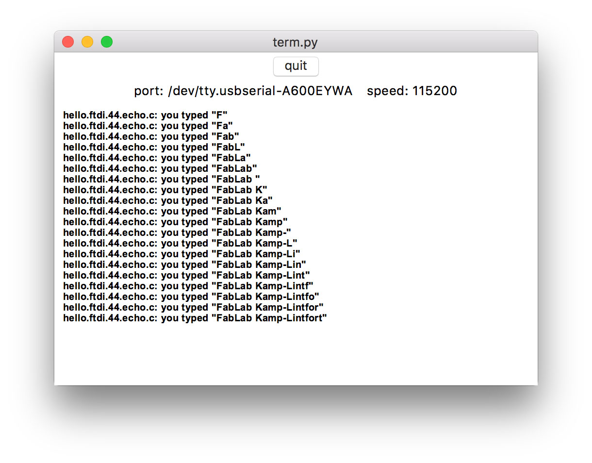
To test the communication using the python script you have to entersudo python term.py /dev/tty.usbserial-A600EYWA 115200 whereas "tty.usbserial-A600EYWA" represents your USB2Serial port. It can be found by entering
ls -al /dev/tty.usb*However, in my case I had lots of trouble to find the USB2Serial device. It just did not appear. After quite a while I realized it must be a drivers problem. I did some reseach on it and discovered that Mac OS El Capitan does not support FTDI properly.
Thus, I installed the FTDI Driver (D2XX Direct Drivers; v2.3), which can be found at http://www.ftdichip.com/Drivers/VCP.htm.
And then tried again and again - wih no success.
Surprisingly the Mac did recognize the FabISP and the FT232R USB UART while entering:
system_profiler SPUSBDataType
kn / $ system_profiler SPUSBDataType
USB:

    USB 3.0 Bus:

      Host Controller Driver: AppleUSBXHCILPTH
      PCI Device ID: 0x8c31
      PCI Revision ID: 0x0005
      PCI Vendor ID: 0x8086

        Apple Internal Keyboard / Trackpad:

          Product ID: 0x0263
          Vendor ID: 0x05ac  (Apple Inc.)
          Version: 2.25
          Speed: Up to 12 Mb/sec
          Manufacturer: Apple Inc.
          Location ID: 0x14400000 / 3
          Current Available (mA): 1000
          Current Required (mA): 40
          Extra Operating Current (mA): 0
          Built-In: Yes

        BRCM20702 Hub:

          Product ID: 0x4500
          Vendor ID: 0x0a5c  (Broadcom Corp.)
          Version: 1.00
          Speed: Up to 12 Mb/sec
          Manufacturer: Apple Inc.
          Location ID: 0x14300000 / 2
          Current Available (mA): 1000
          Current Required (mA): 94
          Extra Operating Current (mA): 0
          Built-In: Yes

            Bluetooth USB Host Controller:

              Product ID: 0x8289
              Vendor ID: 0x05ac  (Apple Inc.)
              Version: 1.12
              Speed: Up to 12 Mb/sec
              Manufacturer: Apple Inc.
              Location ID: 0x14330000 / 5
              Current Available (mA): 1000
              Current Required (mA): 0
              Extra Operating Current (mA): 0
              Built-In: Yes

        Hub:

          Product ID: 0x3301
          Vendor ID: 0x03eb  (Atmel Corporation)
          Version: 3.00
          Speed: Up to 12 Mb/sec
          Location ID: 0x14200000 / 20
          Current Available (mA): 1000
          Current Required (mA): 64
          Extra Operating Current (mA): 0

            FT232R USB UART:

              Product ID: 0x6001
              Vendor ID: 0x0403  (Future Technology Devices International Limited)
              Version: 6.00
              Serial Number: A600EYWA
              Speed: Up to 12 Mb/sec
              Manufacturer: FTDI
              Location ID: 0x14230000 / 24
              Current Available (mA): 1000
              Current Required (mA): 90
              Extra Operating Current (mA): 0

            FabISP:

              Product ID: 0x0c9f
              Vendor ID: 0x1781
              Version: 1.04
              Speed: Up to 1.5 Mb/sec
              Location ID: 0x14220000 / 22
              Current Available (mA): 1000
              Extra Operating Current (mA): 0
Also ioreg -p IOUSB -w0 -l showed details about USB IO devices but they did not appear as devices at "/dev/tty*"I did further research and found the hint "If using a device with standard FTDI vendor and product identifiers, install D2xxHelper to prevent OS X 10.11 (El Capitan) claiming the device as a serial port (locking out D2XX programs)."
So I installed the D2xxHelper and treid again. With no success.
I looked up the FTDI Drivers Installation guide for MAC OS X, Version 1.3
In Section 7 I found interesting details.
7 Disabling the Apple-provided VCP on OS X 10.9 and later
A VCP driver for most FTDI USB to serial converters is provided as part of the kernel in OS X 10.9 and later. OS X loads this driver (AppleUSBFTDI.kext) when a device with standard FTDI vendor and product identifiers is connected. To use FTDI‟s own VCP instead, or to use D2XX programs, AppleUSBFTDI must be disabled, unloaded or blocked, as follows.
...
7.3 Block with D2xxHelper (OS X 10.9 and later)
Note: this is the only non-temporary method which works on 10.11 El Capitan.
FTDI provides a signed kernel extension (D2xxHelper.kext) which contains no code but acts to prevent OS X from matching an FTDI chip (with standard vendor and product identifiers) with a VCP driver, either Apple‟s or FTDI’s. This leaves the device unclaimed, and available for D2XX programs only.
1. Disconnect all FTDI devices.
2. Download and run the D2xxHelper installer from http://www.ftdichip.com/Drivers/D2XX.htm
3. Reboot.
4. Reconnect the FTDI devices.
FINALLY, it worked!
Download
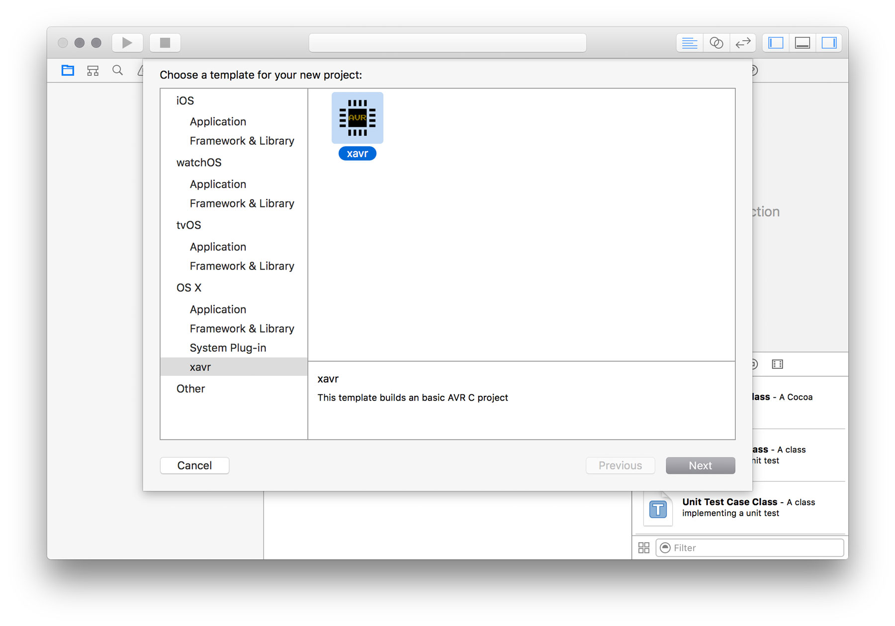
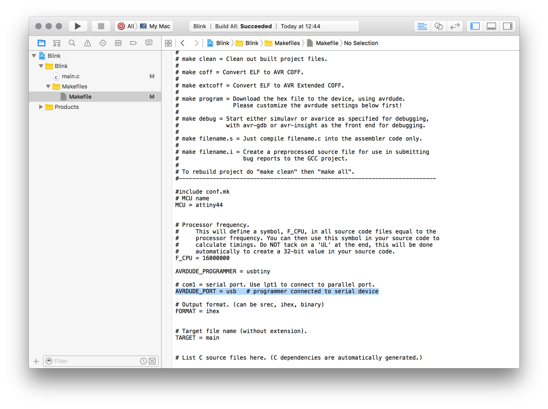
Using xCode for AVR C developement (using the FabISP as programmer)
Due to research I found, that xCode can be used as IDE for programming AVR, too.
Jawher Moussa posted a tutorial on how to setup your XCode for AVR developement (in the C programming language) using X-AVR.
Prequisites
avr-gcc must be installed and in the PATH variable (detectable via a which avr-gcc)
avrdude must be installed and in the PATH variable (detectable via a which avrdude)
Simply install AVR Crosspack to satisfy these prequisites.
Another option is to use homebrew:
brew install avrdude
brew tap larsimmisch/avr
brew install avr-libc
Then, clone the git repository:
git clone https://github.com/jawher/xavr.gitRun
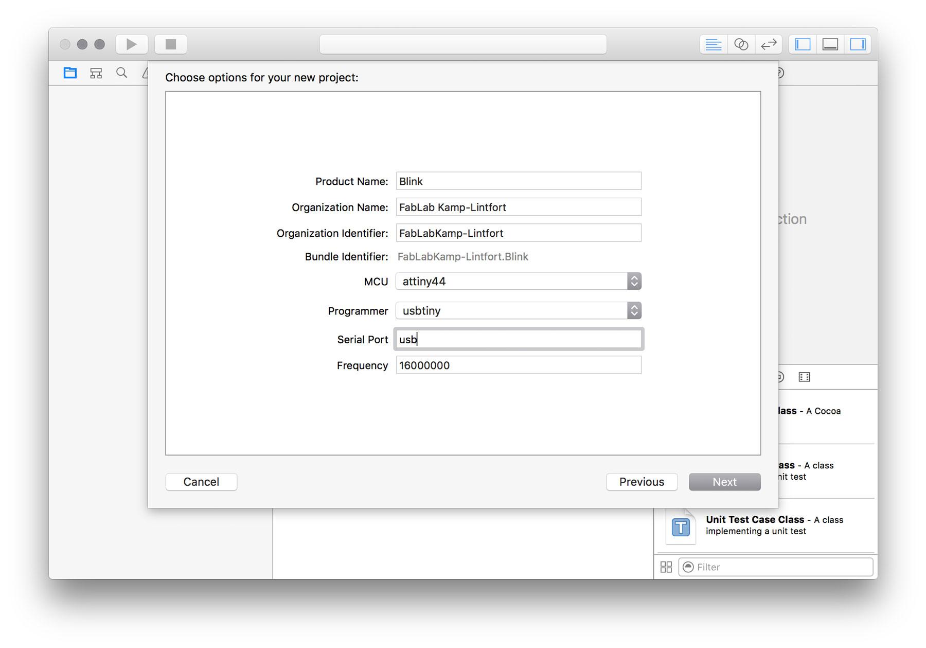
python setup.py to generate and install the XCode project template.Start xCode and open a new Project

Take Away's
- When usng the Arduino IDE - the pins of your ATtiny are not identical with the pins on the Arduino UNO (or other). Here, for the blink example, the digital pin 6 to which I have connected the LED on my HWB needs to be adressed as bit 7 in accordance to the PINA register. Therefore you need to have a look into the processors datasheet.
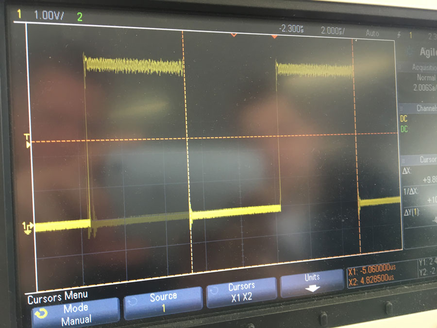
- If performance matters: If you use the Arduino IDE and the code a simple operation, e.g. to enable and disable a port, by using digitalWrite() takes 9,8us (101kHz).
The same operation can be done by bitwise operations (here: OR and AND). The difference in speed is incredible. Booth operations (enable and disable a port) takes 749ns = 0,75us (1,33Mhz). (see comparison)