
E04: Electronics production
In this assignment it was requested to make the FabISP in-circuit programmer, which is an in-system programmer for AVR micro controllers. I choose not to just copy it (from one of the links provided in the course material) but to use EAGLE to create and mill the board.
Thus, I anticipated what might be expected in week 06 (electronics design)
However, in principle this worked quite well. I did the schematics on my own but at the end, when it came to the generation of the board I struggled with the optimization. I could not find a way (in the given time) to come up with a one sided (top layer) board, without vias. Due to limitations of time I decided to copy the board of David A. Mellis.
Even though I copied the board at the end, in principle I understood the process and made (MAKEd) everything by myself. Finally I soldered the ISP and got my first experiences in soldering smd.
-
Assignment:
- Make the FabISP in-circuit programmer Machines/Tools:
- CNC milling machine (Cirqoid), soldering rod & stand, tin-solder, cleaning-sponge, flux-pen Software:
- EAGLE, cirQWizard
Notes from lecture + comments:
- For flexible or very big circuits you can use the vinyl cutter to cut foil of copper.
- Kapton can be also be used for flexible cirquits.
- Don't use copper in a CO2 laser cutter.
- FR4 is glass based; it cannot be machined.
- FR1 can be machined beautifully.
- Design rules define the skinny (width/spacing, e.g. 15, 5 mils) of a trace.
- Octopart is a search-engine for components.
- Do a line-mill check
How to MAKE it
The last time I used EAGLE was in 1995 and I quickly realized that I cannot remember anything. So I could say, this is my fist time, using EAGLE to create a PBC.
To get started with EAGLE I recommend to follow two tutorials, provided by Jerry Blum.
Tutorial 1 for CadSoft Eagle: Schematic Design
Tutorial 1 guides you through the process of designing a PCB. It shows how to „get the program up and running, how to navigate the interface, how to design your first schematic, and how to use DesignConnect to build a Bill-of-Materials.“
Tutorial 2 for CadSoft Eagle: Printed Circuit Board Layout
The second tutorial shows „how to turn your schematic into a board design that you can get manufactured! Specifically, I’ll cover part layout, automatic and manual routing, layer and grid controls, ULPs, ground pours, net classes, and much more!“
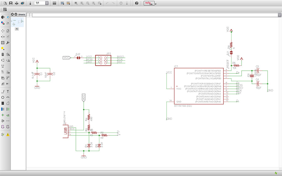
Creating the schematic
(There are further standard operations, such as rotate, delete, etc. which are explained in Jerry's 1st tutorial and do not eed to be mentioned here. I just state the most relevant steps in a logical order.)
- First, you create a new project and create a new schematic (right click on projects name in the project treeview of EAGLEs starting dialog).
- Add the relevant libraries (Menu:Libraries->Use) to your project, i.e. fab.lbr and supply1 and mabye supply2 from the EAGLEs standards libraries.
-
Start adding ("Add" icon) the needed components to your layout.
As a basis for the schematic I used the schematic pdf provided by David.
- Roughly place and arrange the components in the way you like them to be. You will change their position using the "Move" command.
You may want to add/use GND and VCC as components (even though, they could also just be Labels, as shown below). I recommend to use the components. - Create connections using "Net".
- Name the components using "Name" and set their values using "Values";
-
Labels are used to label a net/wire. Labels can have a different appearance. They are used to connect components virtually. This helps to get a better and structured layout as you can create groups of components, as shown in the following picture.
- When you are finished with the schematic you can change to the board view.
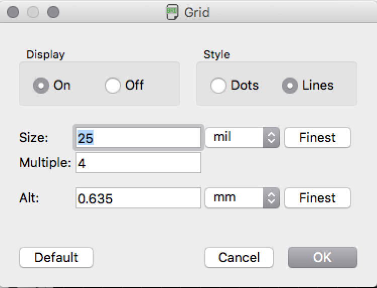
- First, I reccommend to change the grid to 25mil, which is the standard distance on breadboards, etc.
- Then, the next you have to do is to arrange the components. Initially, all of them are placed outside the board. In EAGLE light you have to place all of them at some place on the board to start.
- Later, you may want to resize the board and also, to create a GND layer. See Jerry's 2nd tutorial for the basics.
- "Ratsnest" is used to calculate the shortest awire.
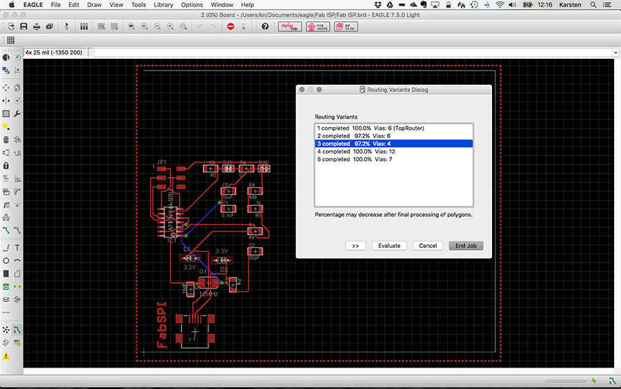
- "Autoroute" calculates the best routing. IMPORTANT: don't press "End Job" in the dialog unless you are satisfied with the final design.
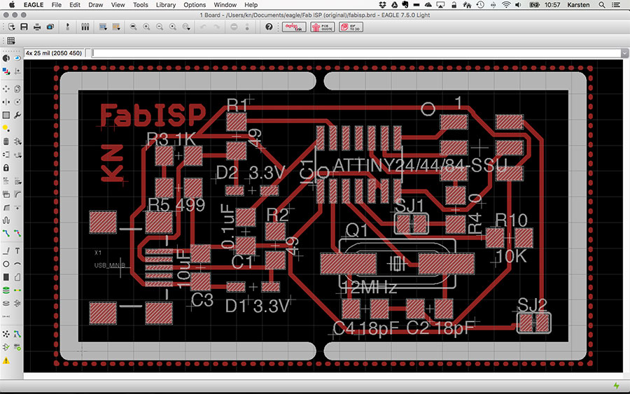
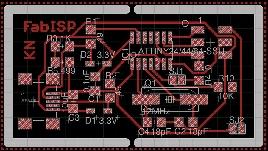
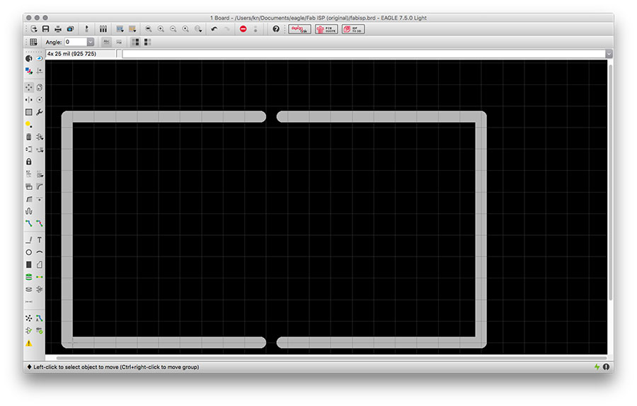
- Create the border for the breakout board. Use Layer 46 and draw lines with a line width of 40.
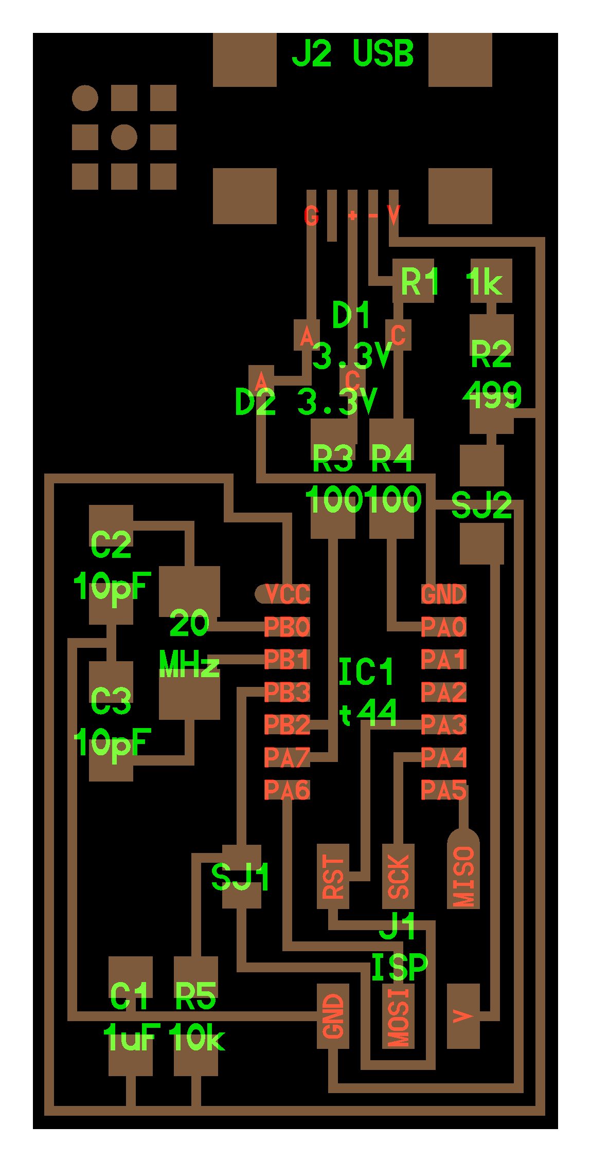
- Finally, the board looked like this:
CAM processing in EAGLE
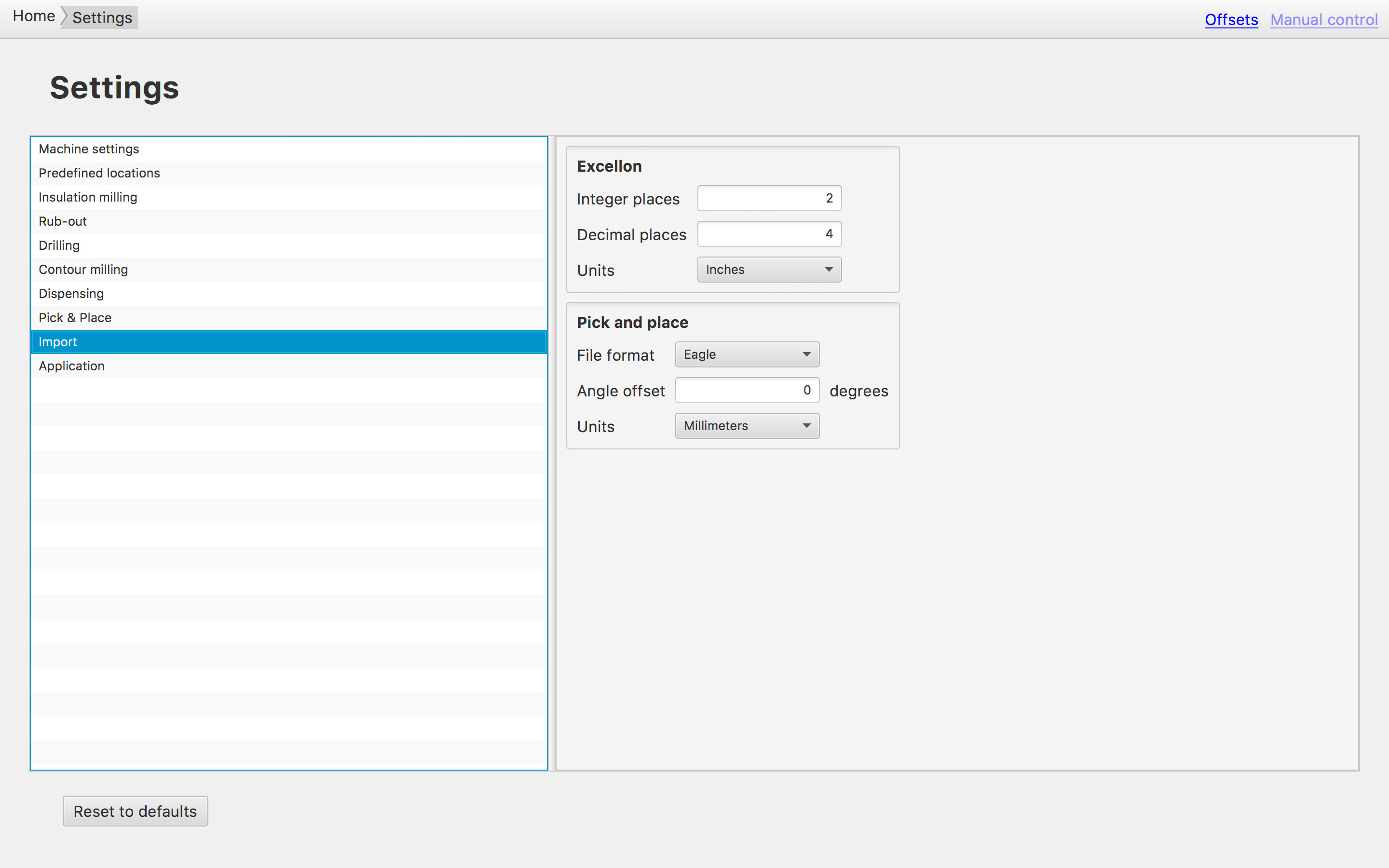
Before milling the board, we need to convert the data in a machine-readable format according to the specifics of the milling machine you are using. This happens though a file in Gerber format (i.e. RS-274X extended gerber format).
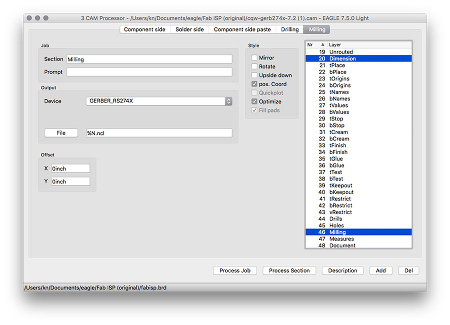
- In EAGLEs board view chose 'File->CAM Processor' in the menu.
- A new dialog opens. Click 'File->Open->Job' and open the gerber-file cqw-gerb274x-7.2.cam
- Goto the tab 'Milling' and select layer '20 Dimensions'.
- Then, click on 'Process Job'.
- Click on File->Save Job
- Click on 'Close' and 'Save'.
- You are now in the board view again. Click on 'File->Run ULP' and open file 'mount-mark-smd.ulp'.
- Confirm to save (2 times).
- Confirm 'Mount Data'.
Milling
In our FabLab we have two smaller CNC milling machines that can be used for printed circuit board prototyping:
a Roland Modela MDX-40A and a Cirqoid-CNC.
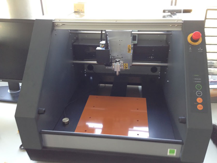
(I choose the Cirqoid for this assignment.)
The Cirqoid is a CNC machine (controlled using standard G-Code). 'The machine accepts various operation specific heads: spindle, solder paste syringe or pick-and-place head. The machine includes all control electronics, built-in air tank for solder paste dispensing and built-in vacuum generator for SMD components placement.' (cirqoid.com)
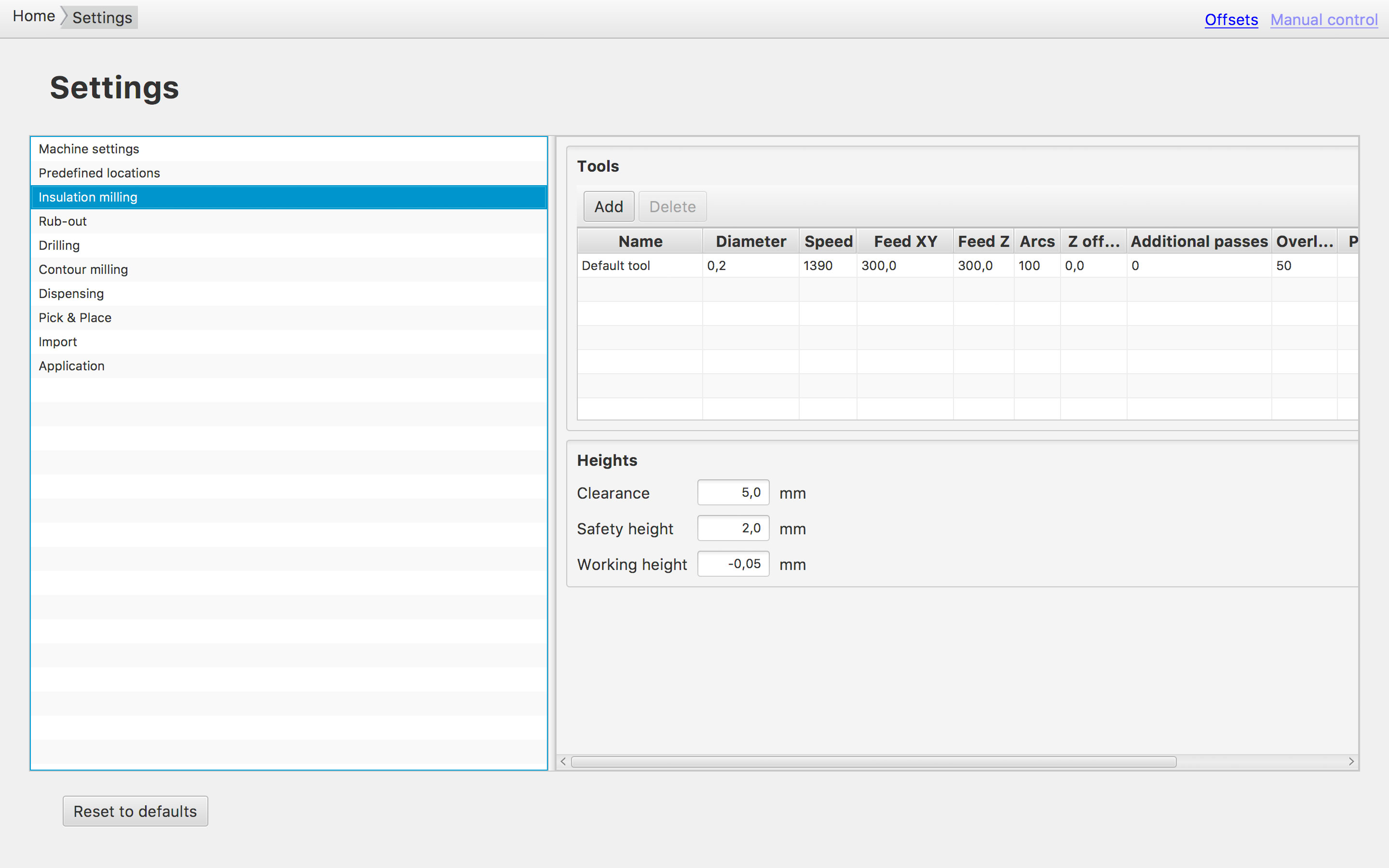
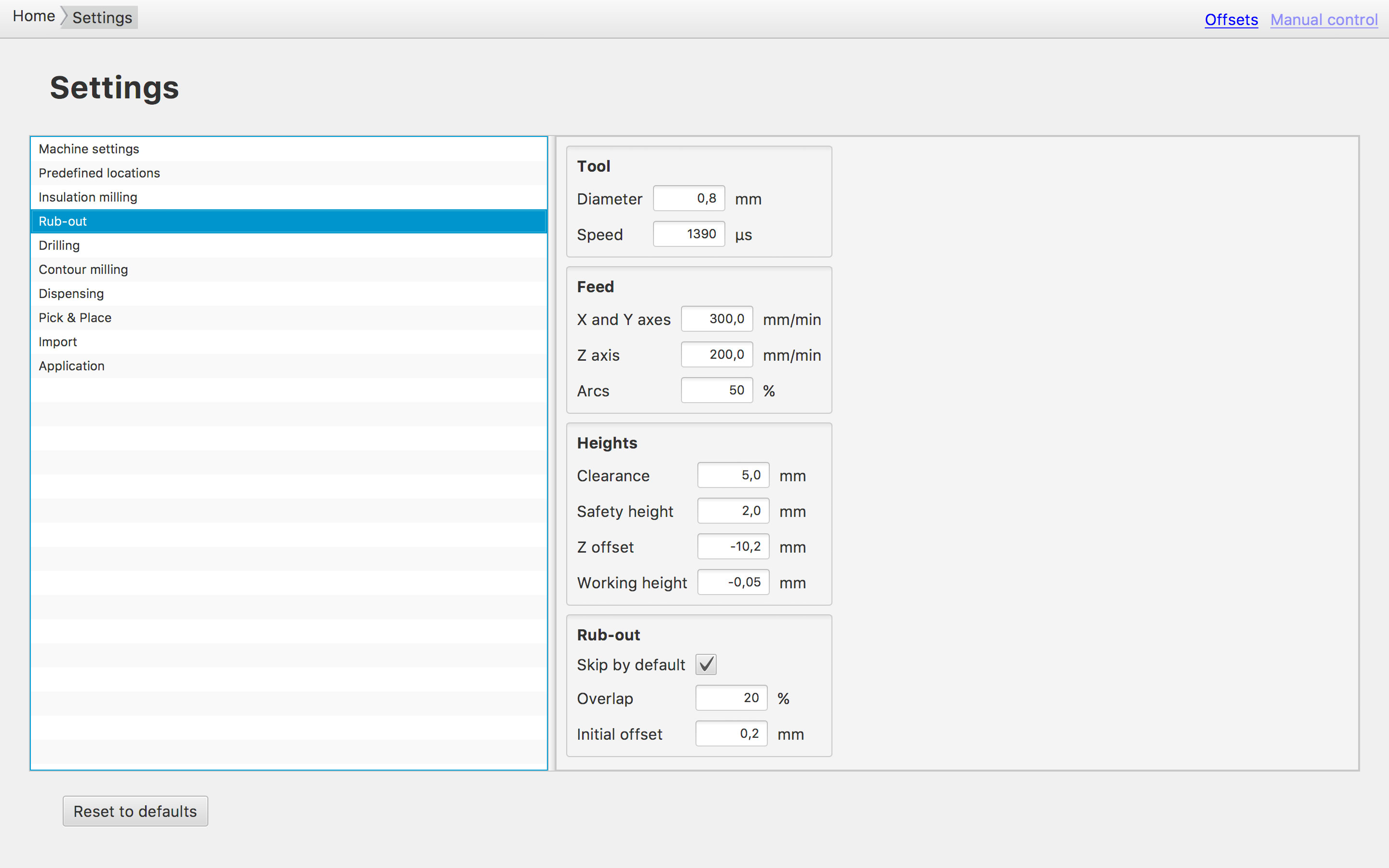
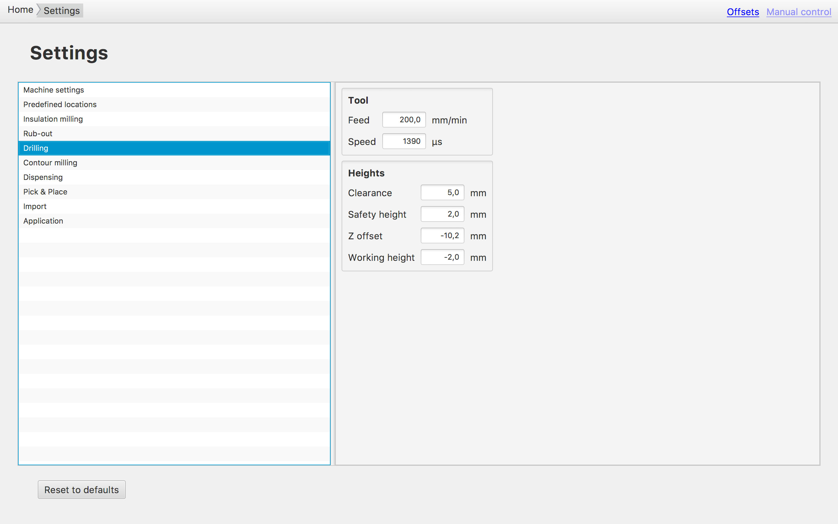
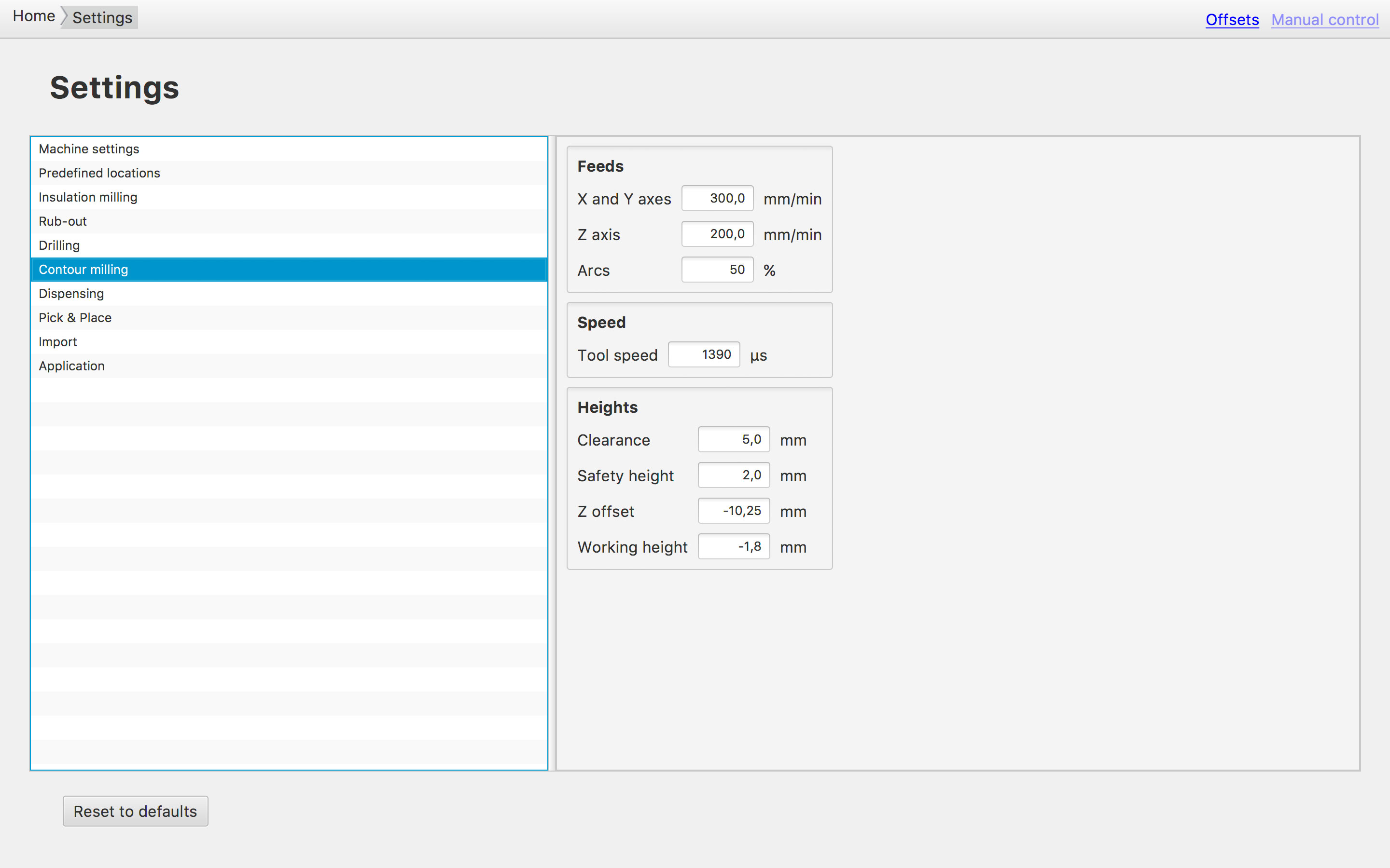
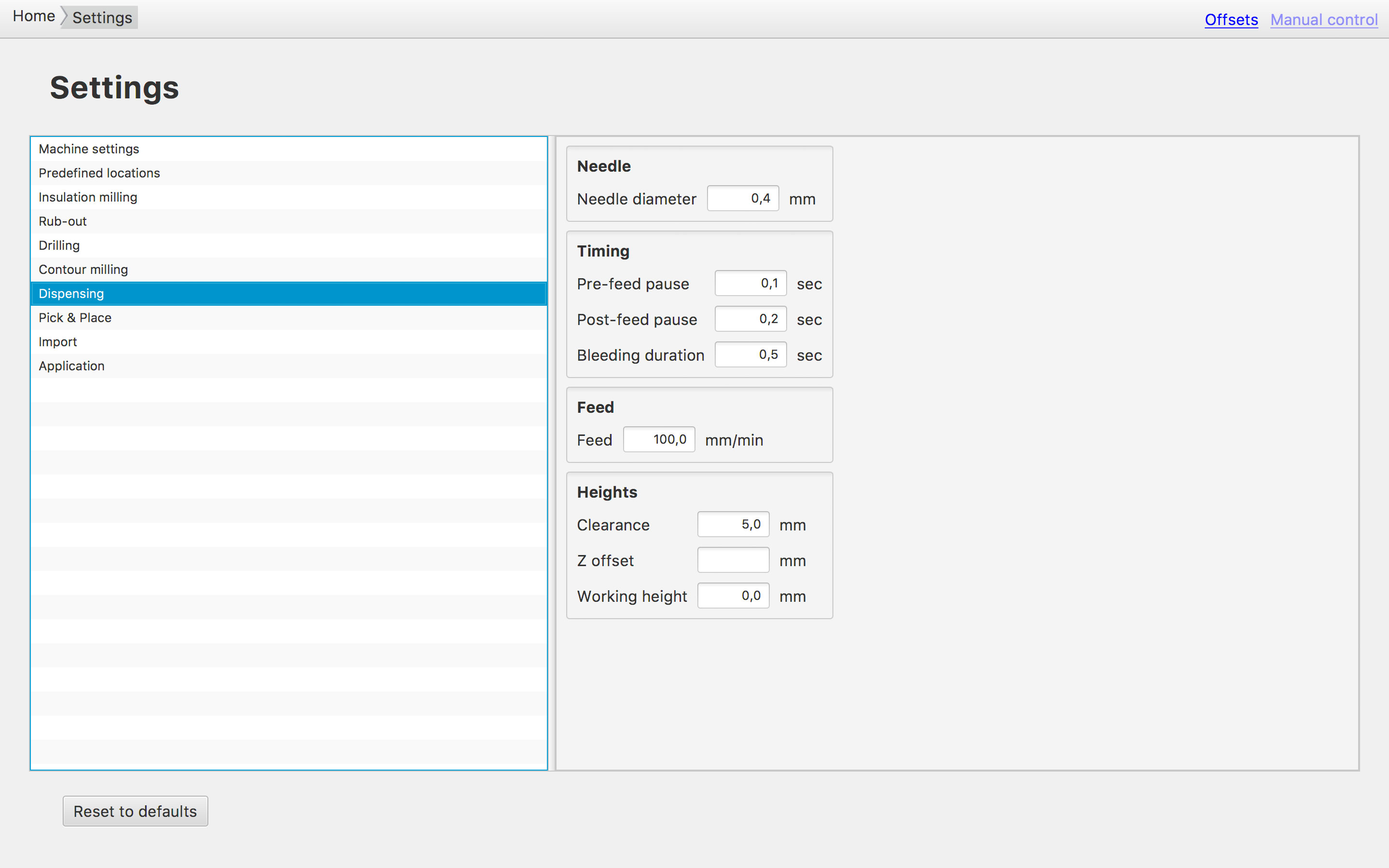
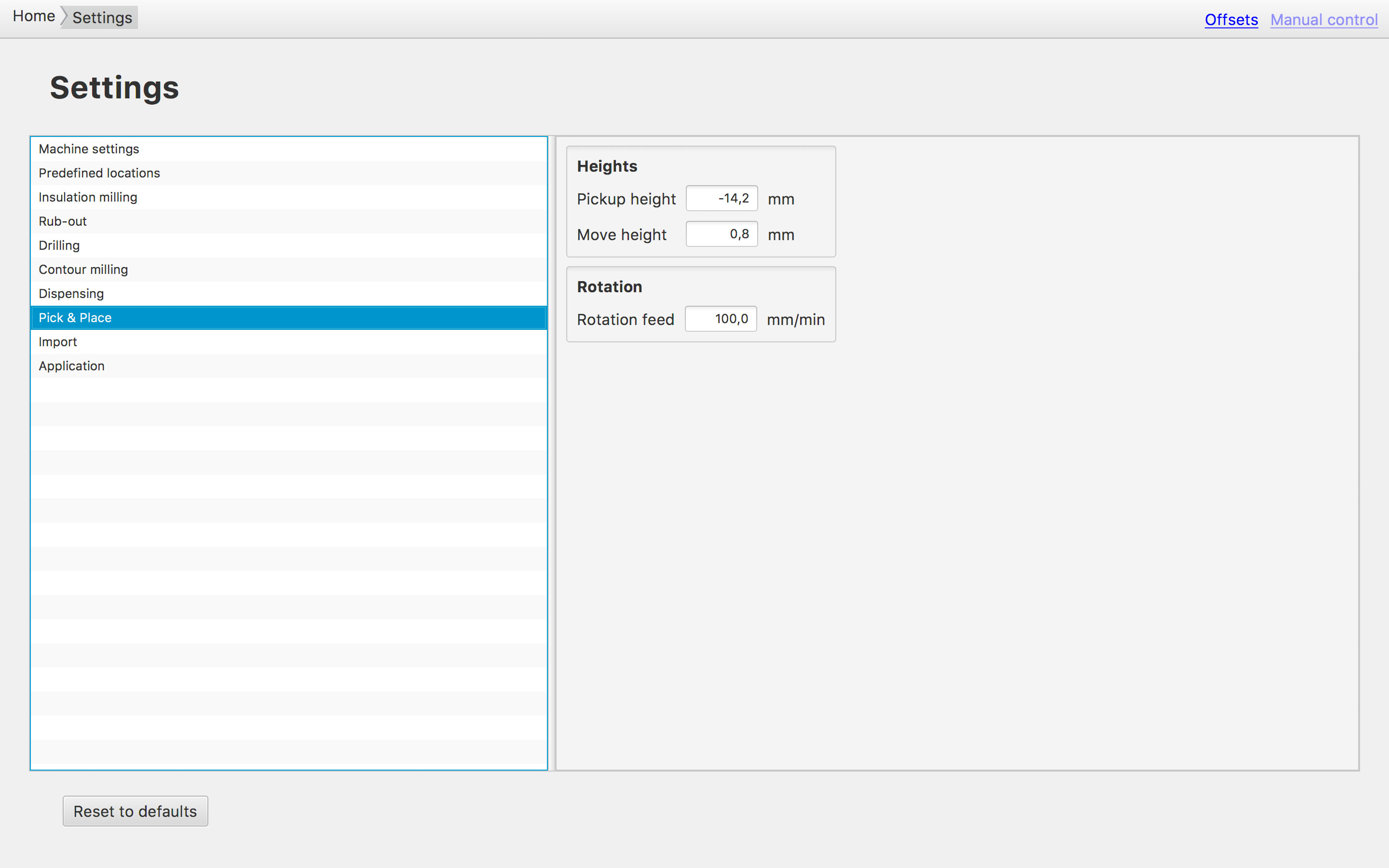
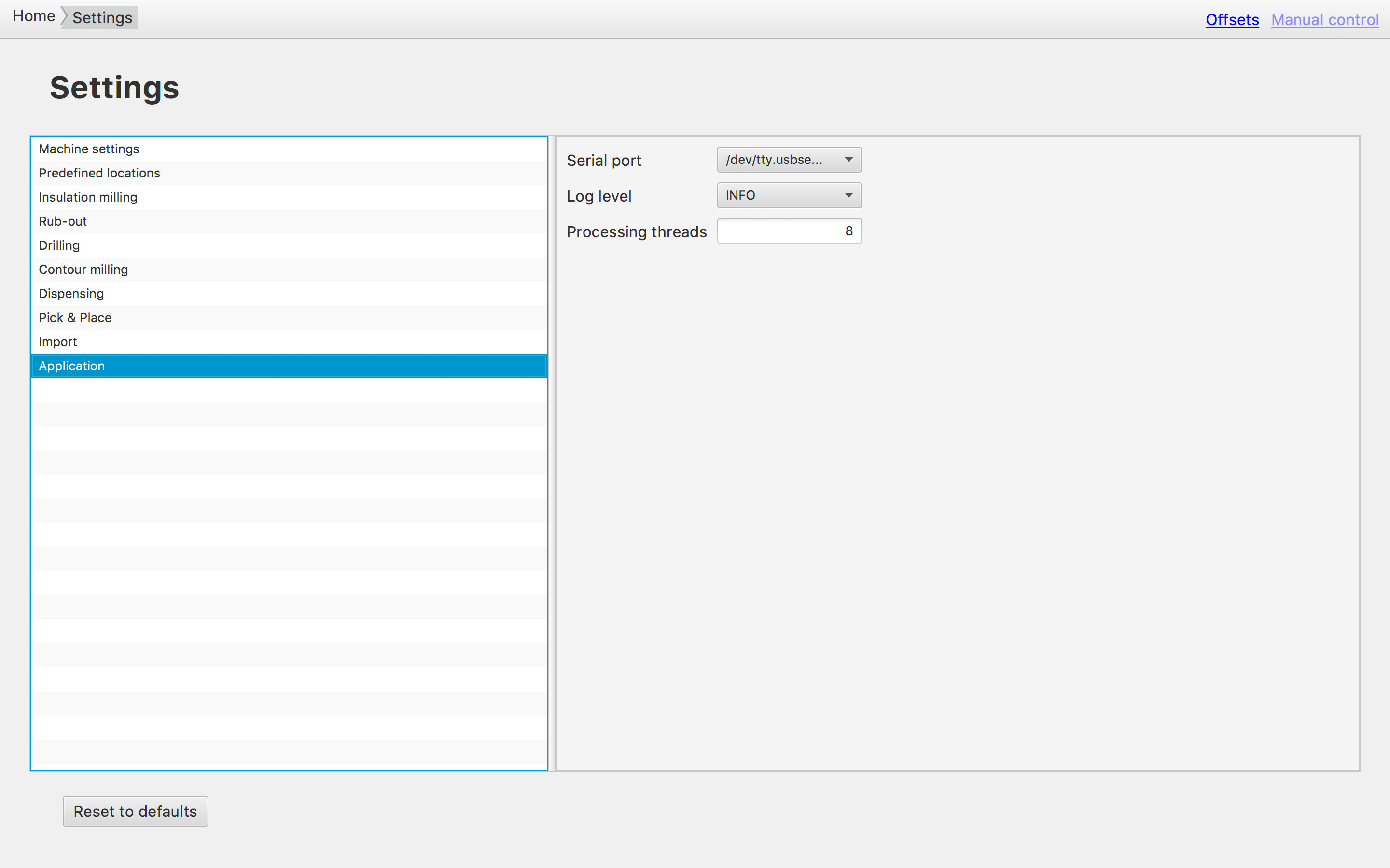
To run the Cirqoid we use cirQWizard. This is a cross-platform open source software designed to control PCB prototyping machines.
In front, I have to say that the software has its difficulties. It took us a while to figure out how to operate the machine in an efficient (and effective) way. Following notes might help to (better) deal with the machines difficulties:
- The machine needs 'homing' before you can do anything. (You can home several times - the more often, the better).
- The machines just comes with standard sizes of tools (endmills).
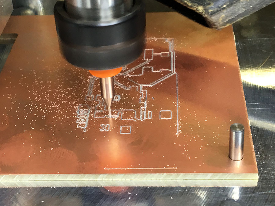
- We use the 0.20 - 0.50 endmill (orange) for the trace milling.
- We use the 2mm endmill for the dimensions (cutting the final size of the board).
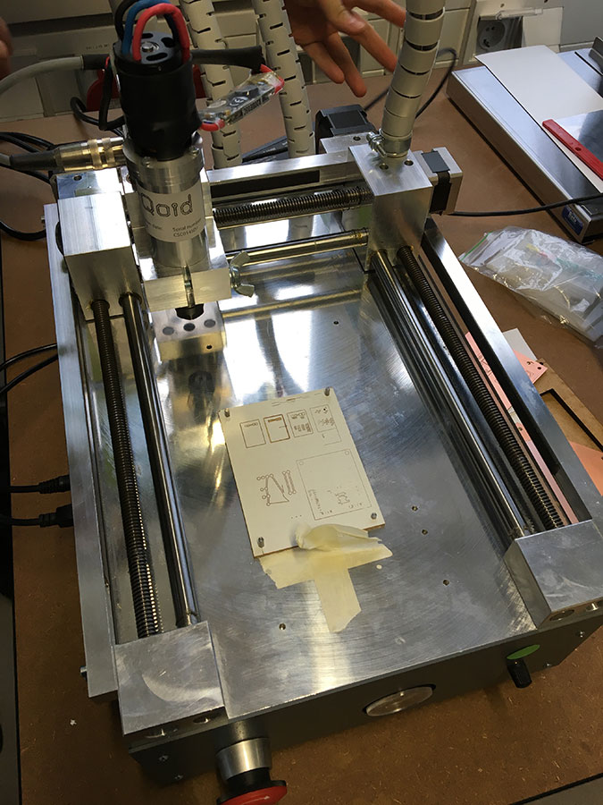
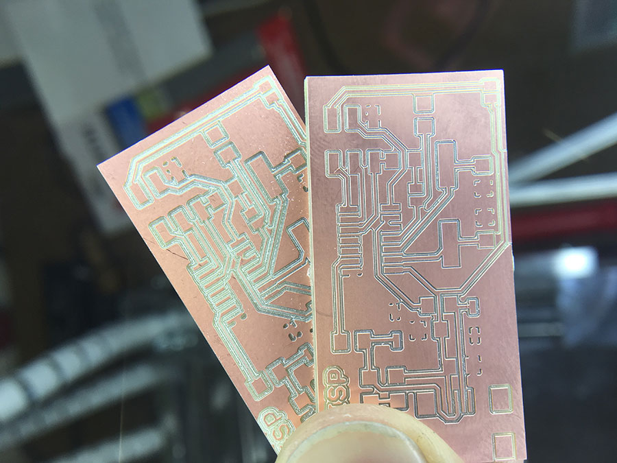
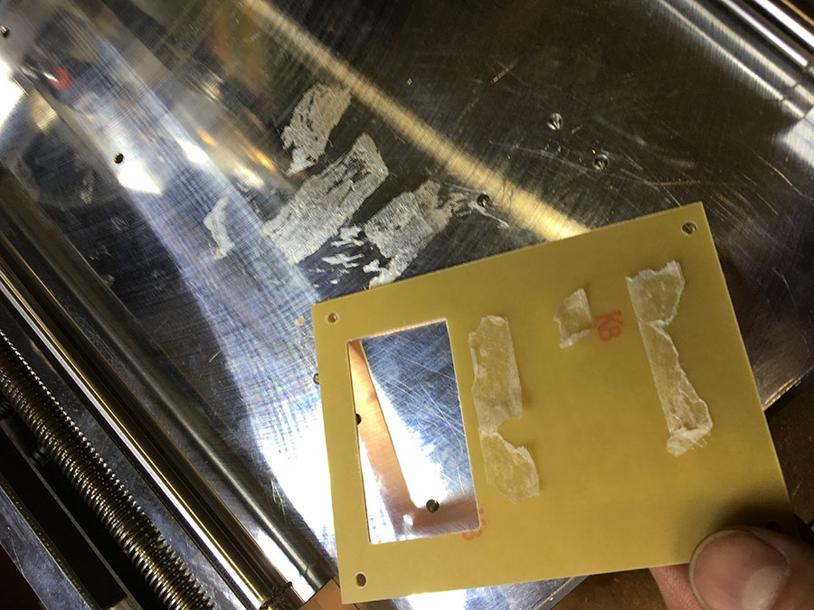
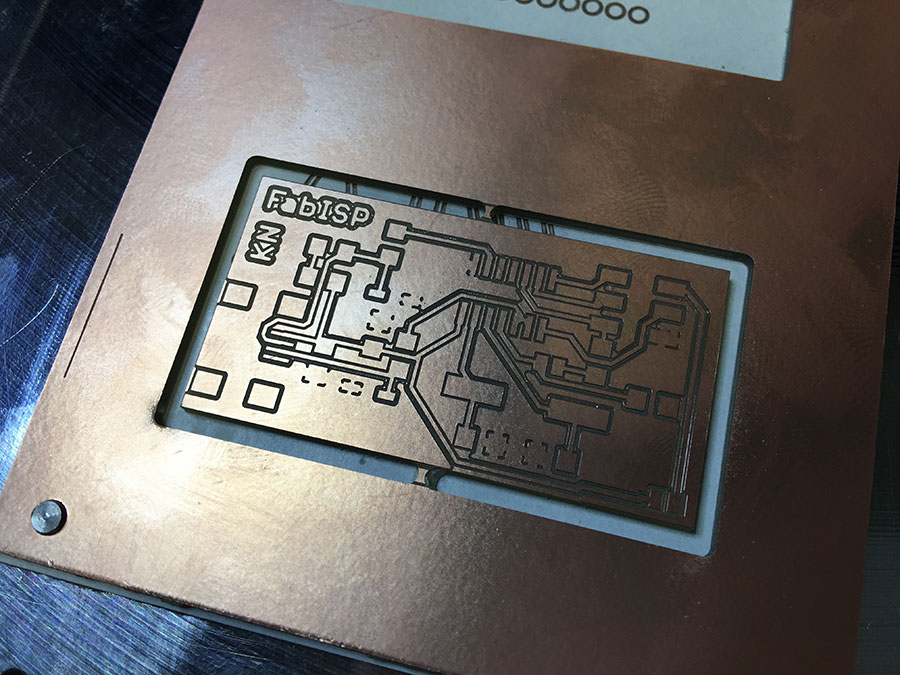
You have to find and set the proper settings in EAGLE. For example, you have to set the width of the lines that define the dimensions of your board to the value 62. This makes the 2mm endmill work to cut your board without loosing traces of your board. - You may want to fix the board using thin double-sided tape (in addition to the fixation pins). If you just use the fixation pins, the board might bend especially in the center. This results in different depths of the traces and therewith also in different width. I used 3 stripes of tape. At the end it was a bit difficult to remove it from the work bench (also to remove the leftover of glue) but the result was very good. The following picture shows the difference in traces when sticking (right) or just fixing (left) the board to the work bench.
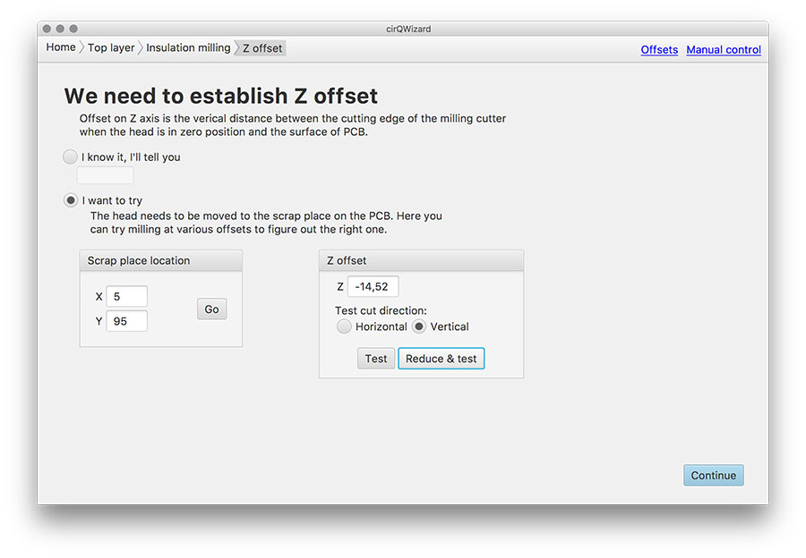
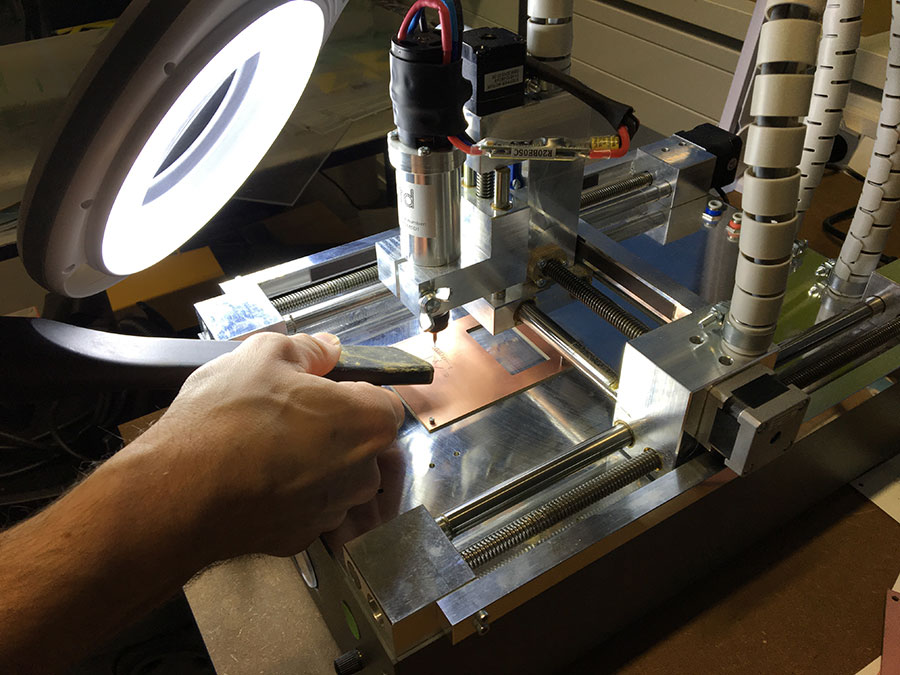
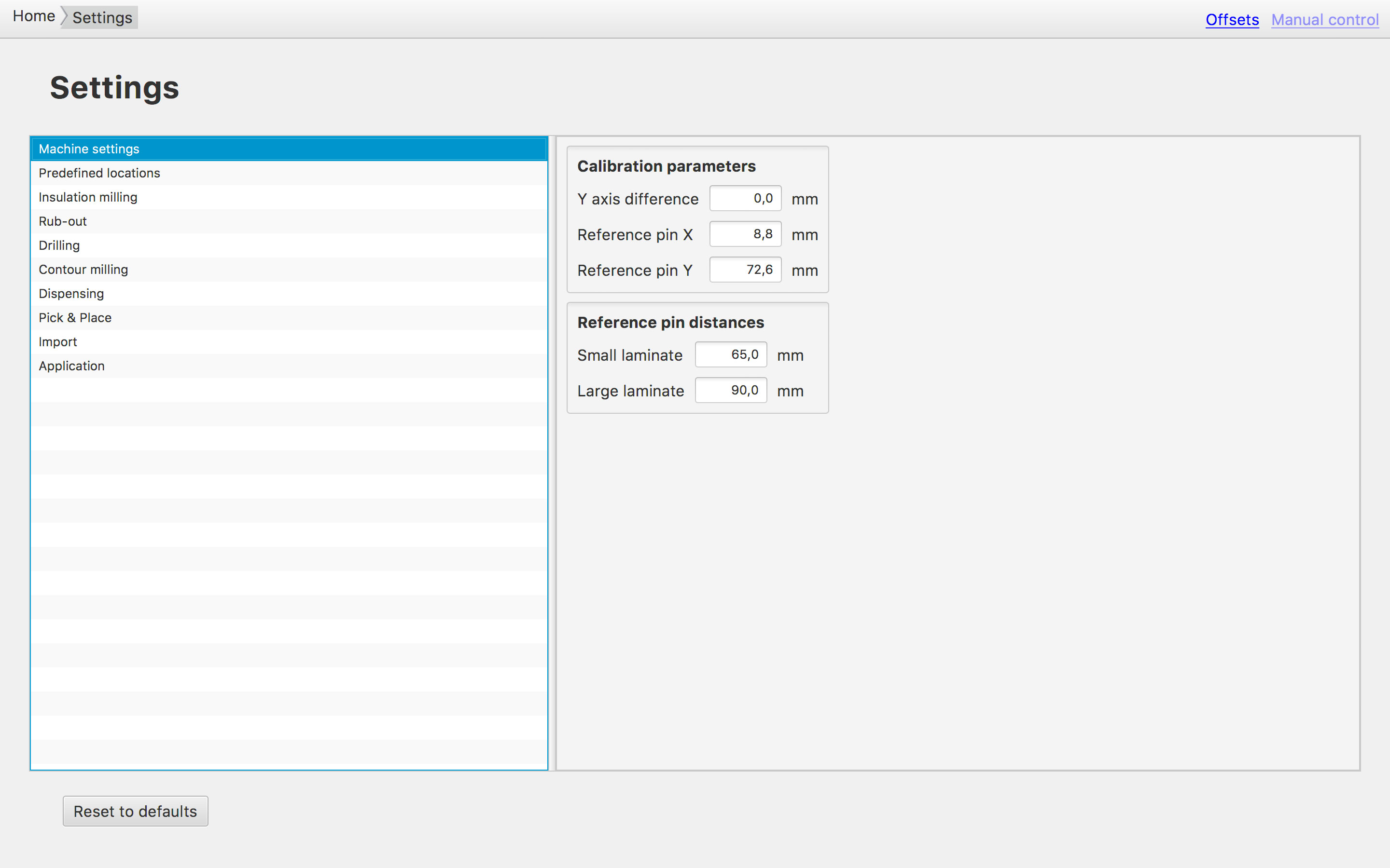
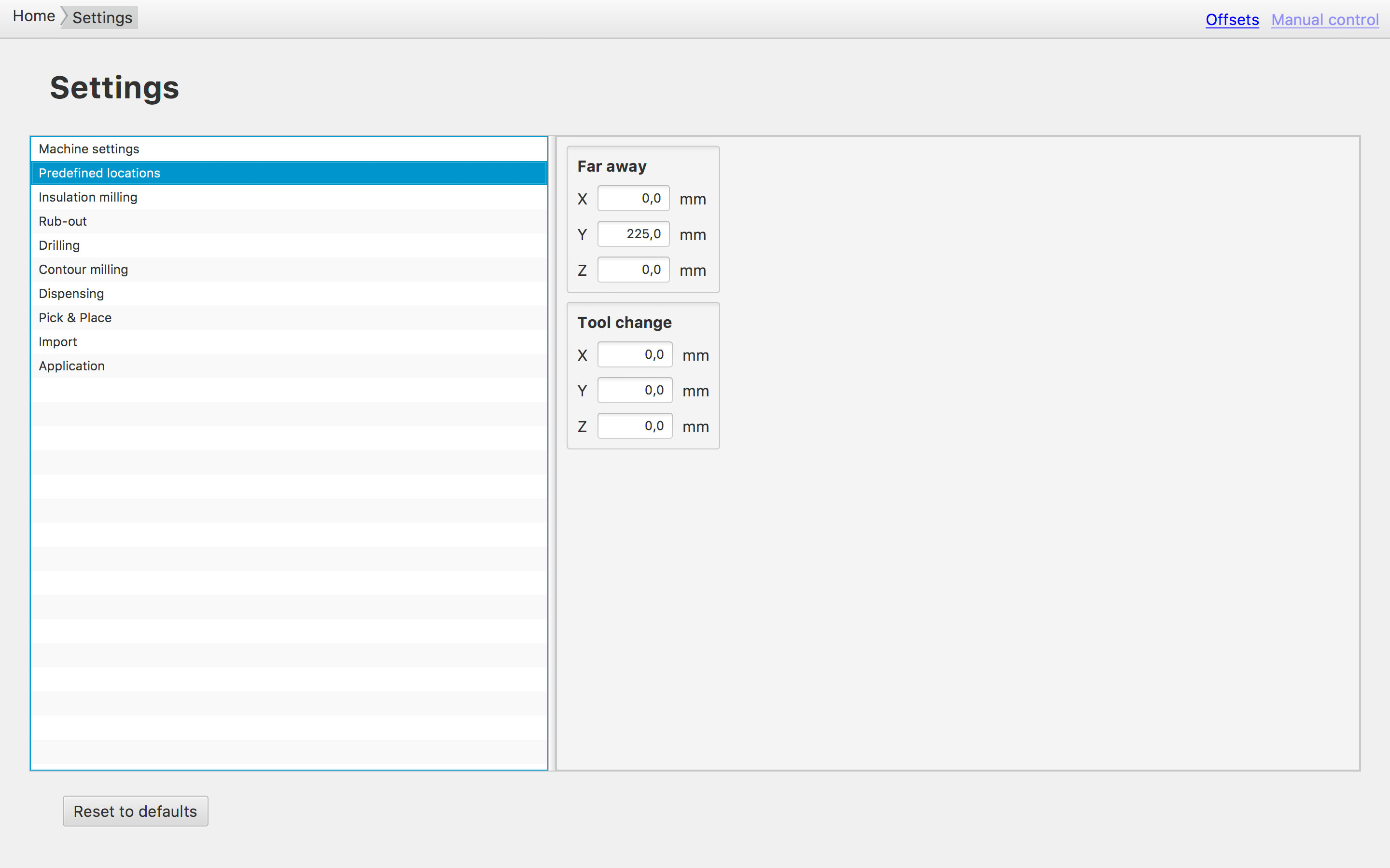
- Setting the Z-offset is challenging because of the controls in cirQWizard. The recommendation is, to use the "Manual control" in order to find a save position (especially the height) of the endmill close to the board. Find a scrap place on your board that does not interfere with the (later) area of your board. Be aware of the "Test cut direction". The test cuts length is approximately 5mm.
Then start making test-cuts using "Reduce & test" until you have made a nice scrap. Take your time! Once you have found the right offset, make note of it.
- You may want to use the vacuum cleaner while milling. It helps the machine to make nicer traces. Just make sure that you do not derail the milling process by touching the spindle.
- You may want to make a board to break out. This keeps the board in position until the very end (avoids shifting during milling). You create a dimensions layer in EAGLE that contains little gaps (here: 2mils).
Soldering
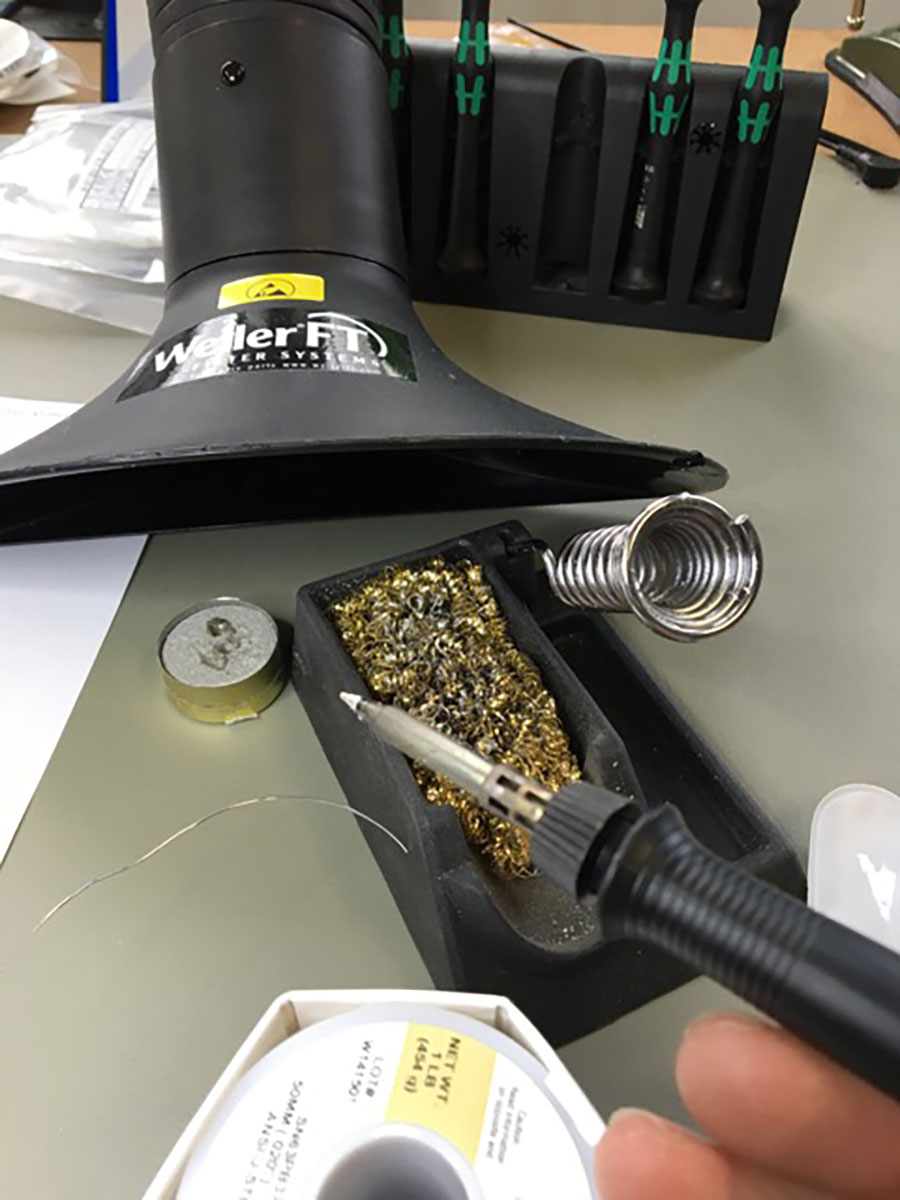
First, prepare the workplace. Put all the components in place, the material and tools (soldering rod & stand, tin-solder, cleaning-sponge, flux-pen). Also clean your board using fine sandpaper (e.g. 600 grain size) and wash it with dish liquid to remove fats.

While soldering, it is sometimes recommended to put some tin-solder onto a pad before you place the component. It works best, if you do this only on one pad. If you put tin-solder to more pads of one component it is harder to place/arrange the component because it is tough to have all pads heated up at the same time. As a result the components may slope.
I have to say, the soldering was way easier then expected. I was fun doing it.
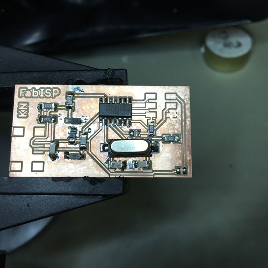
At the end I realized, that I made a mistake. By accident I must have deleted one trace (from R10 to SJ2). I fixed it using a wire as you can see in the lower right corner.
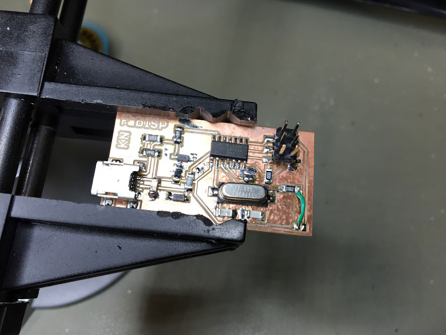
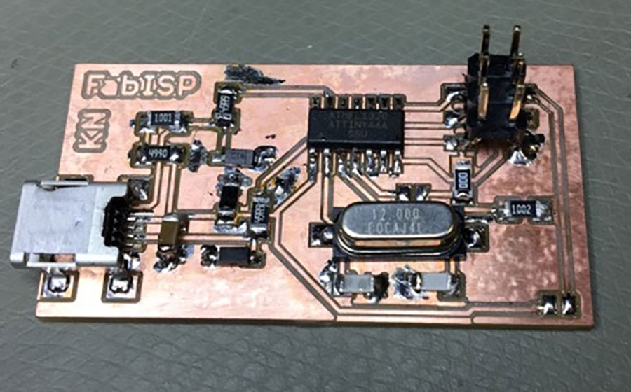
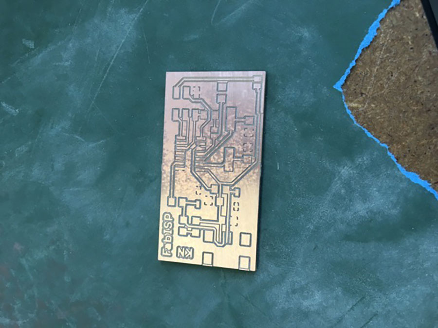
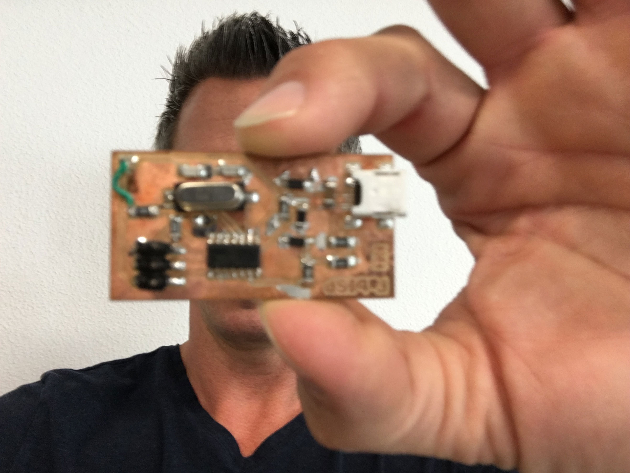
Finally, I got my first smd-board ready to go. However, before connecting it to my computer I performed a quality check.
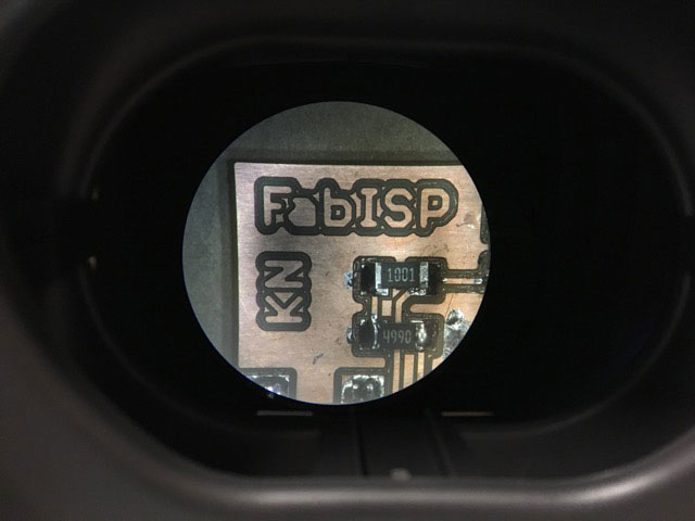
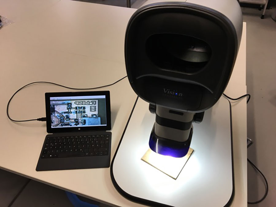
Quality Check
I first checked the board visually using a microscope. By doing this I found a solder bridge which was not intended to be there. By heating the pins, the solder easily moved away.
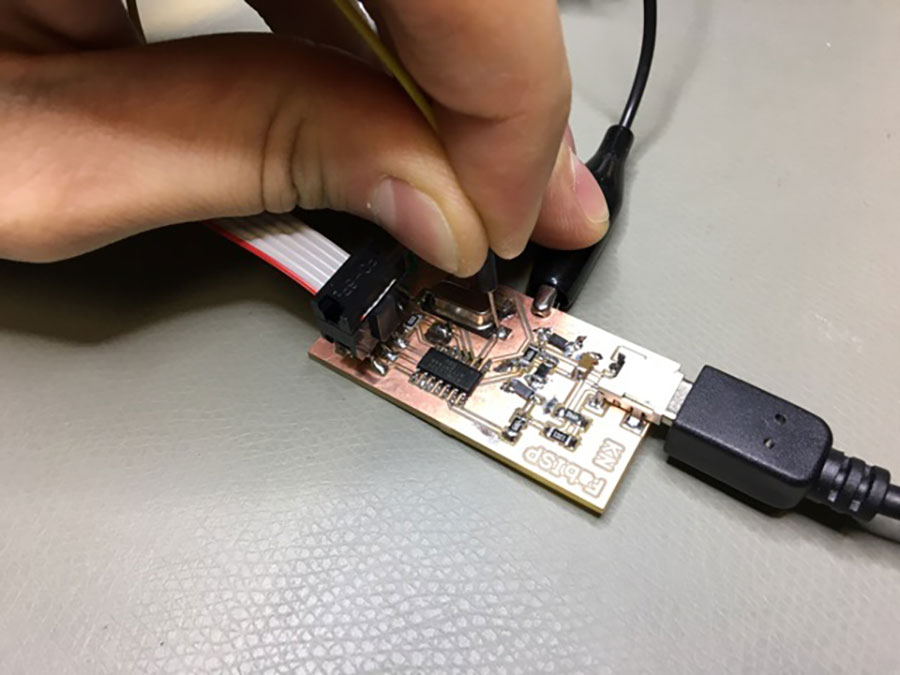
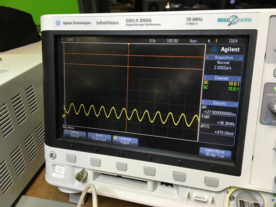
After visual control I did some continuity tests and measurements (e.g. checking the clock signal using the oscilloscope). Also, because I faced some problems in programming the ISP (see below). By doing this I discovered that the clock didn't send a signal. The reason for that was, that SJ1 ans SJ2 needed to be closed. (again, see below).
Programming the ISP
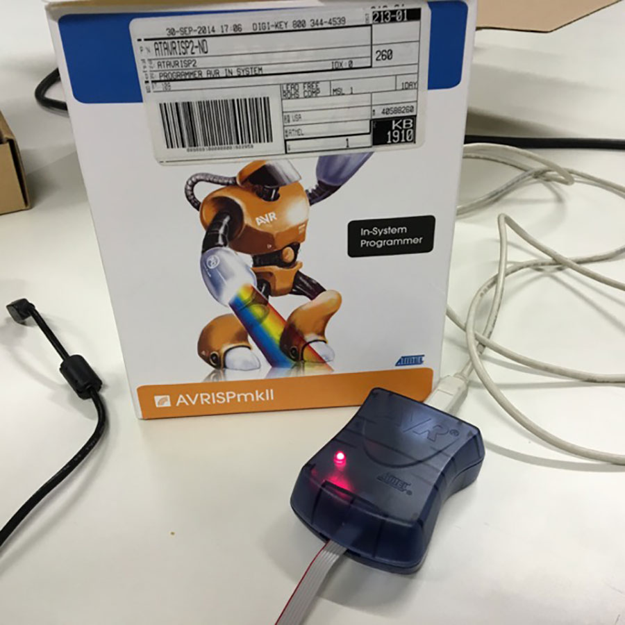
To program my FabISP I used the AVR ISP mark II programmer.
I downloaded the CrossPack for AVR® Development from Objective Development.
'CrossPack is a development environment for Atmel’s AVR® microcontrollers running on Apple’s Mac OS X, similar to AVR Studio on Windows. It consists of the GNU compiler suite, a C library for the AVR, the AVRDUDE uploader and several other useful tools.' (CrossPack for AVR® Development)
By having it installed I can run avrdude as required in David's instructions.
Following Davids instructions, I faced problems in executing the 'make fuse' command. Following error message appeared:
make fuse
avrdude -c avrispmkii -P usb -p attiny44 -U hfuse:w:0xDF:m -U lfuse:w:0xFF:m
avrdude: stk500v2_command(): command failed
avrdude: stk500v2_program_enable(): bad AVRISPmkII connection status: Target not detected
avrdude: initialization failed, rc=-1
Double check connections and try again, or use -F to override
this check.
avrdude done. Thank you.
make: *** [fuse] Error 1
It took me a while to solve the problem. First I thought it was a USB problem but it wasn't. Then I checked the board again visually and by measurements (see above). It turned out that the clock did not work. 'Target not detected' also implied, that there was no connection to talk to the AtTiny. I then realized that there must be a vcc problem. After reading the AVRISP MkII manual (see below) I found the solution:
-
SJ1 and SJ2 must be soldererd!
SJ1 (between the crystal and microcontroller needs to be closed to program the ATtiny44 on the FabISP. (Connects reset on the 2x3 ISP header with reset on the ATtiny44.)
SJ2 (lower right corner of the board needs to be closed to provide power to the target board being programmed by the FabISP. (Connects VCC on the board with VCC on the ISP header.) -
USB power (connect AVR programmer AND connect the Fab ISP to USB). So you have 2 USB cables connected to your computer.
“When using the AVRISP MkII programmer 'VCC must be connected to the target board in order to get correct operation and voltages on the ISP/PDI lines. VCC does not draw any power from the target.“
http://www.atmel.com/webdoc/avrispmkii/index.html make cleanmake hex- Modify the Makefile: “AVRDUDE = avrdude -c avrispmkii -P usb -p $(DEVICE)“
(sudo) make fuse(sudo) make program- Desolder SJ1 and SJ2
Another way to program the ISP: using Arduino as ISP
After using the AVR ISP mark II programmer I decided to try with an Arduino, as it is more easy to find in Fab Labs and you can of course use it for other purposes. Also there are several tutorials on how to do this for example the one in the official Arduino pages: Arduino as ISP.As written in the tutorial you have to make sure to load the Arduino as ISP sketch before try to use the Arduino as an ISP. To do this I did the following steps:
- open the Arduino IDE
- open the arduino as ISP sketch doing File->Examples->1.1ArduinoISP->ArduinoISP
- press the upload button
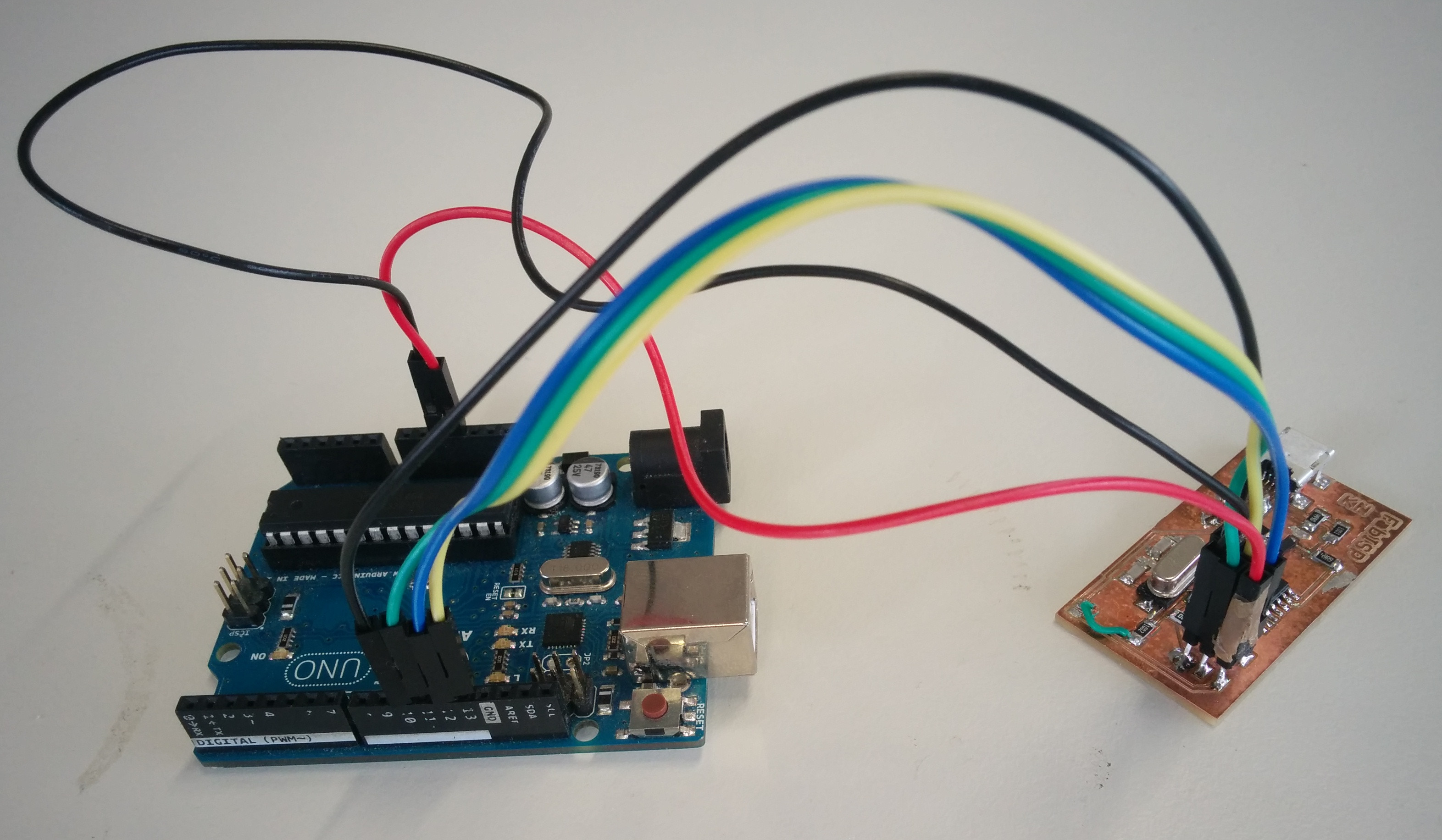
Then I connected the Arduino to the FabISP looking at connections info of the following images:
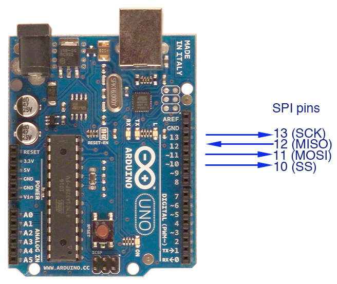
As shown in the next image:
Checking the lecture I remember that we need to modify the Makefile in order to use another programmer. In this case the avrdude string to identify the Arduino as programmer is "stk500v1". Trying with this change, I got programming errors about the invalid port. So I added a parameter to specify the speed of the serial connection: "-b19200", and the arduino serial port "/dev/tty.usbmodem1411". Then it has worked.
In the end I had to change the following line of the Makefile from:
avrdude -c avrispmkii -P usb -p attiny44to this one:
avrdude -c stk500v1 -P /dev/tty.usbmodem1411 -p attiny44 -b19200
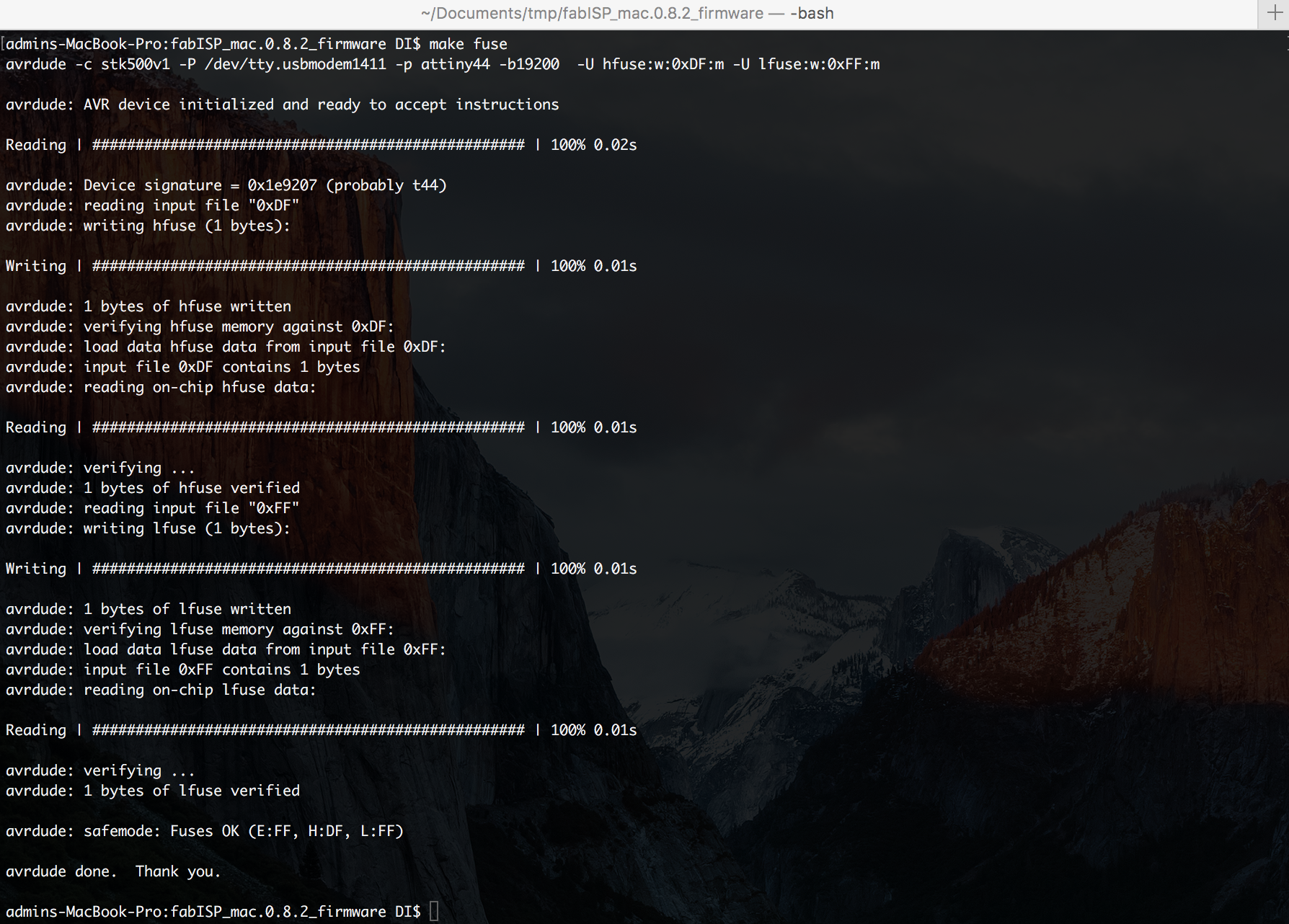
Here you can see a screenshot about the successful fuses:
And following here is the complete successful log of the FabIsp programming:
admins-MacBook-Pro:fabISP_mac.0.8.2_firmware DI$ make clean
rm -f main.hex main.lst main.obj main.cof main.list main.map main.eep.hex main.elf *.o usbdrv/*.o main.s usbdrv/oddebug.s usbdrv/usbdrv.s
admins-MacBook-Pro:fabISP_mac.0.8.2_firmware DI$ make hex
avr-gcc -Wall -Os -DF_CPU=20000000   -Iusbdrv -I. -DDEBUG_LEVEL=0 -mmcu=attiny44 -c usbdrv/usbdrv.c -o usbdrv/usbdrv.o
avr-gcc -Wall -Os -DF_CPU=20000000   -Iusbdrv -I. -DDEBUG_LEVEL=0 -mmcu=attiny44 -x assembler-with-cpp -c usbdrv/usbdrvasm.S -o usbdrv/usbdrvasm.o
avr-gcc -Wall -Os -DF_CPU=20000000   -Iusbdrv -I. -DDEBUG_LEVEL=0 -mmcu=attiny44 -c usbdrv/oddebug.c -o usbdrv/oddebug.o
avr-gcc -Wall -Os -DF_CPU=20000000   -Iusbdrv -I. -DDEBUG_LEVEL=0 -mmcu=attiny44 -c main.c -o main.o
main.c:88:13: warning: always_inline function might not be inlinable [-Wattributes]
 static void delay ( void )
             ^
avr-gcc -Wall -Os -DF_CPU=20000000   -Iusbdrv -I. -DDEBUG_LEVEL=0 -mmcu=attiny44 -o main.elf usbdrv/usbdrv.o usbdrv/usbdrvasm.o usbdrv/oddebug.o main.o
rm -f main.hex main.eep.hex
avr-objcopy -j .text -j .data -O ihex main.elf main.hex
avr-size main.hex
   text    data     bss     dec     hex filename
      0    1986       0    1986     7c2 main.hex
admins-MacBook-Pro:fabISP_mac.0.8.2_firmware DI$ make fuse
avrdude -c stk500v1 -P /dev/tty.usbmodem1411 -p attiny44 -b19200  -U hfuse:w:0xDF:m -U lfuse:w:0xFF:m

avrdude: AVR device initialized and ready to accept instructions

Reading | ################################################## | 100% 0.02s

avrdude: Device signature = 0x1e9207 (probably t44)
avrdude: reading input file "0xDF"
avrdude: writing hfuse (1 bytes):

Writing | ################################################## | 100% 0.01s

avrdude: 1 bytes of hfuse written
avrdude: verifying hfuse memory against 0xDF:
avrdude: load data hfuse data from input file 0xDF:
avrdude: input file 0xDF contains 1 bytes
avrdude: reading on-chip hfuse data:

Reading | ################################################## | 100% 0.01s

avrdude: verifying ...
avrdude: 1 bytes of hfuse verified
avrdude: reading input file "0xFF"
avrdude: writing lfuse (1 bytes):

Writing | ################################################## | 100% 0.01s

avrdude: 1 bytes of lfuse written
avrdude: verifying lfuse memory against 0xFF:
avrdude: load data lfuse data from input file 0xFF:
avrdude: input file 0xFF contains 1 bytes
avrdude: reading on-chip lfuse data:

Reading | ################################################## | 100% 0.01s

avrdude: verifying ...
avrdude: 1 bytes of lfuse verified

avrdude: safemode: Fuses OK (E:FF, H:DF, L:FF)

avrdude done.  Thank you.

admins-MacBook-Pro:fabISP_mac.0.8.2_firmware DI$ make program
avrdude -c stk500v1 -P /dev/tty.usbmodem1411 -p attiny44 -b19200  -U flash:w:main.hex:i

avrdude: AVR device initialized and ready to accept instructions

Reading | ################################################## | 100% 0.02s

avrdude: Device signature = 0x1e9207 (probably t44)
avrdude: NOTE: "flash" memory has been specified, an erase cycle will be performed
         To disable this feature, specify the -D option.
avrdude: erasing chip
avrdude: reading input file "main.hex"
avrdude: writing flash (1986 bytes):

Writing | ################################################## | 100% 2.88s

avrdude: 1986 bytes of flash written
avrdude: verifying flash memory against main.hex:
avrdude: load data flash data from input file main.hex:
avrdude: input file main.hex contains 1986 bytes
avrdude: reading on-chip flash data:

Reading | ################################################## | 100% 1.44s

avrdude: verifying ...
avrdude: 1986 bytes of flash verified

avrdude: safemode: Fuses OK (E:FF, H:DF, L:FF)

avrdude done.  Thank you.

avrdude -c stk500v1 -P /dev/tty.usbmodem1411 -p attiny44 -b19200  -U hfuse:w:0xDF:m -U lfuse:w:0xFF:m

avrdude: AVR device initialized and ready to accept instructions

Reading | ################################################## | 100% 0.03s

avrdude: Device signature = 0x1e9207 (probably t44)
avrdude: reading input file "0xDF"
avrdude: writing hfuse (1 bytes):

Writing | ################################################## | 100% 0.01s

avrdude: 1 bytes of hfuse written
avrdude: verifying hfuse memory against 0xDF:
avrdude: load data hfuse data from input file 0xDF:
avrdude: input file 0xDF contains 1 bytes
avrdude: reading on-chip hfuse data:

Reading | ################################################## | 100% 0.01s

avrdude: verifying ...
avrdude: 1 bytes of hfuse verified
avrdude: reading input file "0xFF"
avrdude: writing lfuse (1 bytes):

Writing | ################################################## | 100% 0.01s

avrdude: 1 bytes of lfuse written
avrdude: verifying lfuse memory against 0xFF:
avrdude: load data lfuse data from input file 0xFF:
avrdude: input file 0xFF contains 1 bytes
avrdude: reading on-chip lfuse data:

Reading | ################################################## | 100% 0.01s

avrdude: verifying ...
avrdude: 1 bytes of lfuse verified

avrdude: safemode: Fuses OK (E:FF, H:DF, L:FF)

avrdude done.  Thank you.

admins-MacBook-Pro:fabISP_mac.0.8.2_firmware DI$
Download
Take Away's
- Soldering was easier than expected.
- The process took longer than expected :)