week 15 | 2016/05/11 - 2016/05/18 | networking and communications
20
This week we had to establish a connection between at least two processors.
This assignment is even very helpful for my final project, because every bogie will include its own processor and will communicate to my mainboard in the middle part. To test if my code works, I made a very simple PCB, which is capable to communicate with a clone of itself via UART.
20
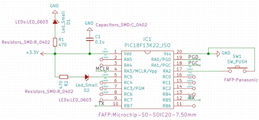
The PCB itself is very simple. I used a small PIC18 as processor. One LED (D1) which indicates if the board is powered. The second LED (D2) is assigned to the RC5 pin. The button (SW1) is used as simple input device. When you push the button on one board, the LED (D2) will flash on the other board, which is connected via UART (see pins 10 and 11 - TX and RX).
21
20
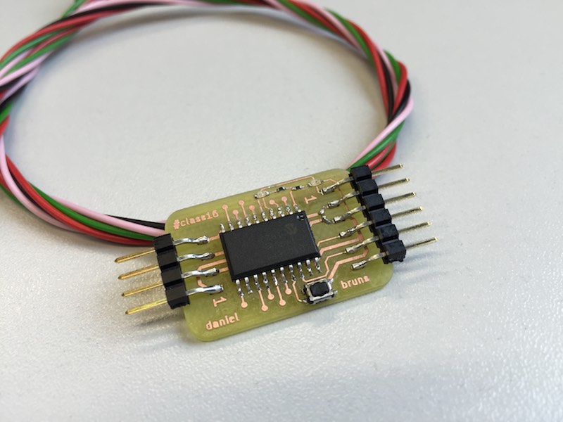
As this board should be a simple example to check if the UART connection works, I made it with simple 0.1" pin header. The 4pin header is for the UART to the other board. The 6pin header is the ICSP header to program the PIC.
22
23
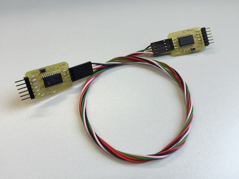
To include the "two processor" factor, I made a cable which is between both milled PCBs. As you can see, both boards are completely identical.
24
20
As my code is not finished yet, the communication does not work - but I'm still working on this. When there are further information, I'll add them to my repository.
20
Download my KiCad design files, to make your own board!

This work by Daniel Bruns is licensed under a Creative Commons Attribution-NonCommercial-ShareAlike 4.0 International License.