Output devices.
Thirteenth week
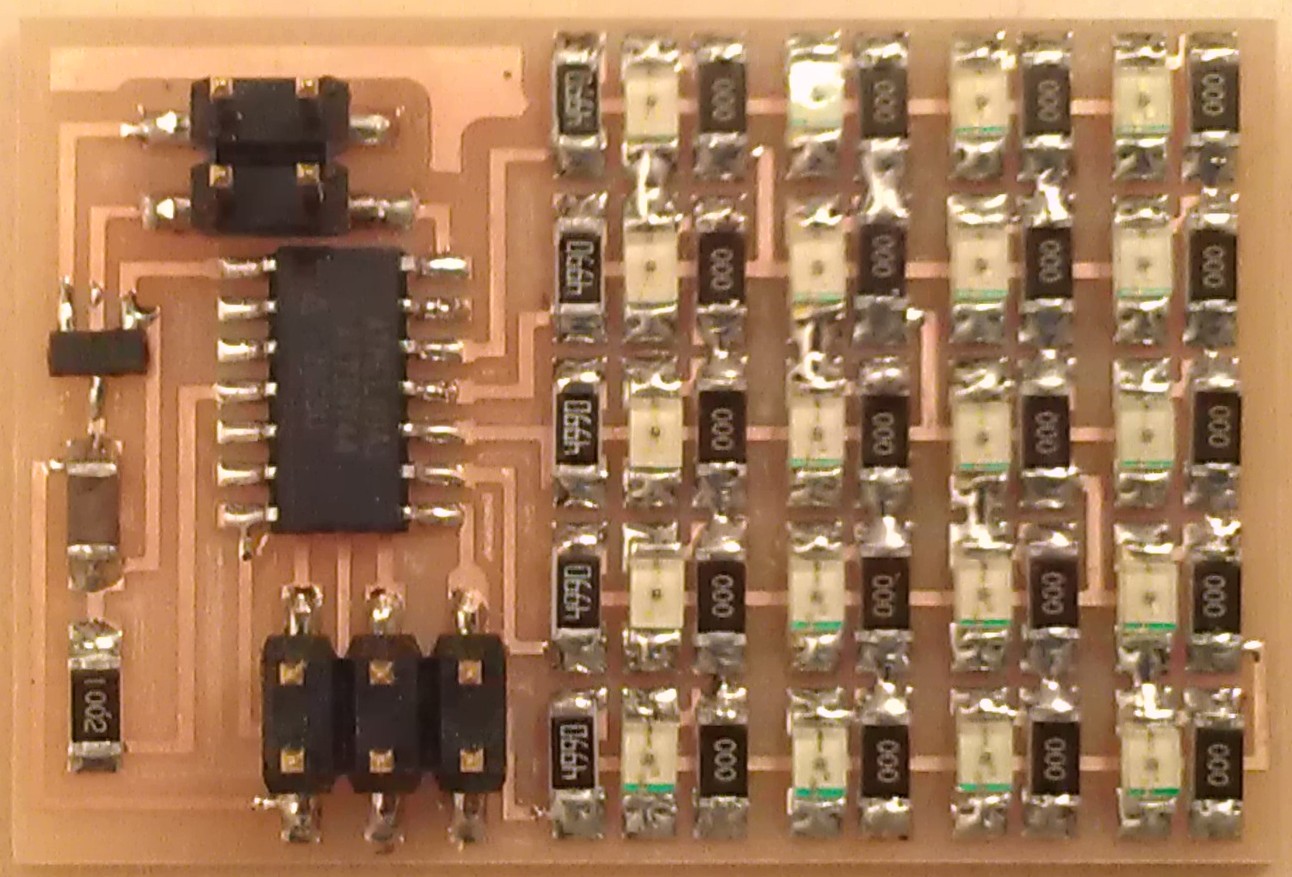
In this week we must make an output device. I've chosen a led array, to advance the job with my final project.
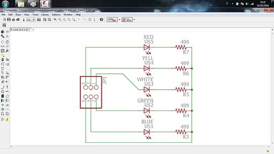
For my projec wasn't necessary all that lines, so I thinked a smaller one, with just five leds, one green, one yellow and three reds.
However I decided to try something else too: a separated board for devices and a different one for the microcontroller.
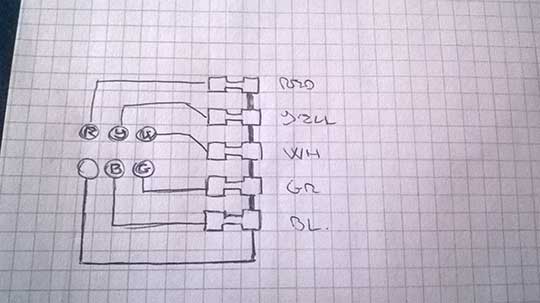
When my brain started melting, making the Eagle traces, I thinked something simple and stupid but very useful: draw the traces by hand first.
This thing simplified my work a lot, and avoided my usual huge waste of time of making traces.
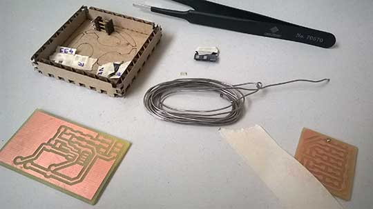
Files here: Led traces and Led board.
I exported the png image, always in a 1600 resolution, and modified the file with a drawing program, to make traces and board files.
So I fast started with the led board milling.
The milling process was made with the Roland SMR-20 using Fab Modulesto modify the png files.
I set five offsets for the interiors, and 0,2 depth for the board.
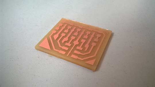

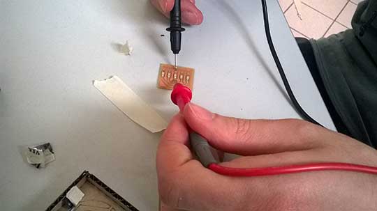
The cutted board, and than the soldering process.
To be sure that the leds was correctly placed, I use a "technique": I touch the led with the tester, and the (low) amount of energy was sufficent to turn on the led lights.
I connected the light board with the sound board of the eleventh week, and connected by cables in the fifteenth week.
Copyleft © Alessandro Patrizi 2016