
NETWORKING AND COMMUNICATIONS
WEEK 14
Task:
Design and build a wired &/or wireless network connecting at least two processors
Build a wired network
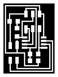
Hellobus.45
The assigment of this week is make the asyn serial communication board between one bridge and tree nodes. It is maily used for communication between diffrents parts. The master only can trasnfer data and slave are the devices that respond to the master
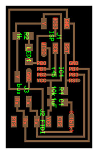
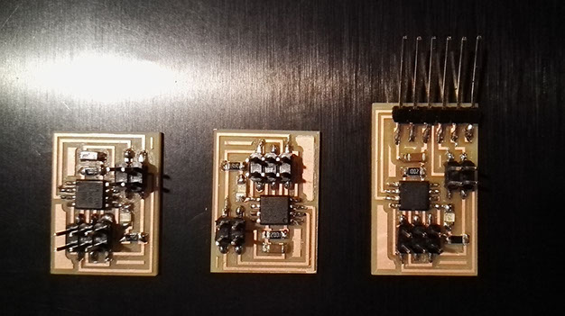
BRIDGE
-
Components:
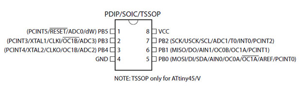
- ATtiny45
- Resistor 1k
- Resistor 10k
- Capacitor 1uF
- Led SMD
- 2 x 3 jumper jack
- 1 x 6 jumper jack

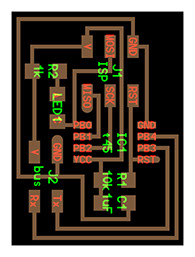
NODE X2
- Components:
-
- ATtiny45
- Resistor 1k
- Resistor 10k
- Capacitor 1uF
- Led SMD
- 2 x 3 jumper jack
- 2 x 2 jumper jack

BRIDGE
(MASTER)
NODE
(SLAVE)
NODE
(SLAVE)
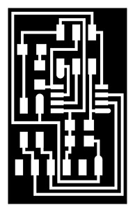
Follow the workflow of the pcb board milling and welding process in this week (week 04)
Programming
Linux
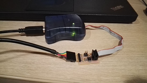
BRIDGE
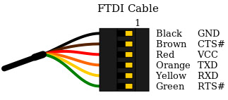
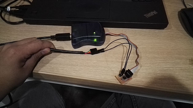
Connect the AVRISP mkII to the bridge board and FTDI cable (5V), the AVRISP who writes the data on the bridge board and the FTDI cable is used used as a transmitter of data to the computer and as a power supply.
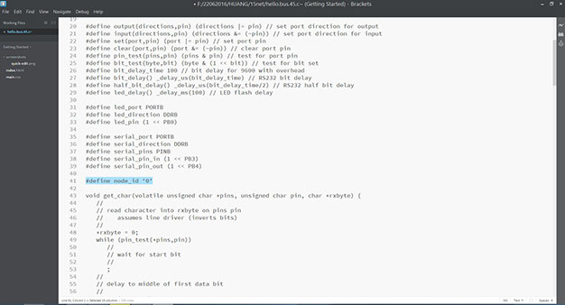
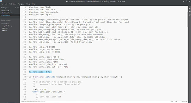
The next step is download hello.bus.45.c, open it with brackets or notepad and modify the C file as the image below :
#define node_id '0'
Open the terminal in ubuntu and write this code for flash the node board.
sudo make -f hello.bus.45.make program-avrisp2

NODE
Connect just GND and VCC pinouts of the FTDI cable the the node board GND and VCC pinout as a power supply with jumper wires.
Repeat the previous steps, but now modify the hello.bus.45.c file and write instead "0" to "1" , Repeat this step for the next node and write instead "1" to "2"
#define node_id '0'
Modify the hello.bus.45.c file and write instead "0" to "1" for the node 1
Modify the hello.bus.45.c file and write instead "0" to "2" for the node 2

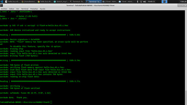
Screenshot of the flash verified
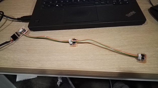
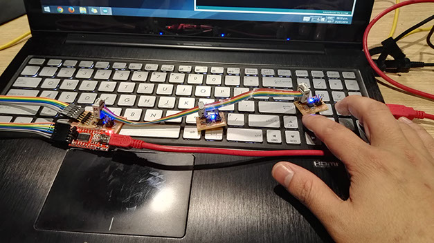
Connect the boards with a energy cable flat and connect FTDI Cable to the bridge board
ARDUINO IDE
Open Arduino ide
- Tools / Serial Monitor
- Select Bauds ratio 9600
- Write "0", "1" or "2" and check the leds of the board turn on consecutively
.jpg?crc=472172359)
.jpg?crc=3825416865)
Problems / fix
At the beginning , I couldn't flash the boars because I had the LEDs flipped , so I returned to weld it again and could flash the board
The LEDS has cathode and anode. So before to soldering the board I need to check the schematic.
Learning outcomes
- Demonstrate workflows used in network design and construction
- Implement and interpret networking protocols
Have you:
- Described your design and fabrication process using words/images/screenshots
- Explained the programming process/es you used.
- Outlined problems and how you fixed them
- Included original design files and code
Download files of week 15
Copyright © Jorge Huang Li - FAB ACADEMY 2016