
OUTPUT DEVICES
WEEK 13
Task:
Add an output device to a microcontroller board you've designed and program it to do something
Tools and equipment:
- Milling machine: Roland MDX-20 mill
- Milling cutter: 1/64 for mill the circuits and 1/32 for cut the board
- Welding tools: Soldering iron stand, soldering wire and solder paste
- Multimeter
Software:
- Eagle
- Gimp
Environment:
- Ubuntu terminal
- Python
Output device
Hello.servo.44
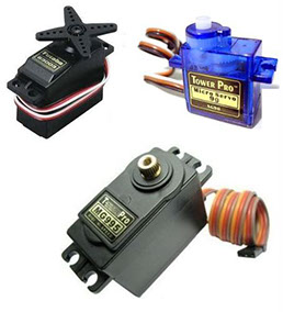
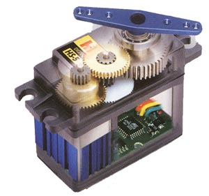
For the assignment of this week is similar to the input devices week (week 11), but in this case we going to use attiny44a microcontroller for program the output devices. The idea of this week is make a board that I can use for my final project. The servomotor is similar to DC motor that has the ability to placed in any position within 180 degrees.
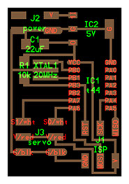
Componets:
- Attiny 44a
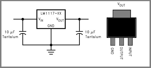
- Regulator 5v SOT-223
- Capacitor 22uF
- Resistor 10k ohms
- Cristal 20 mhz
- 2x3 Header 6 FTDI
- 2x2 Header 4
- Board

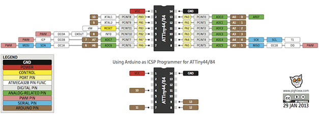
DATASHEET
ATtiny44/ATtiny84 microcontroller is small and cheap that can run simple programs. The only disadvantage is that it has low memory to program many functions.
- Parameter
-
- 14 Pin count
- 4 kBytes of flash memory
- 256 Bytes EEPROM
- 256B SRAM
- 4 PWM pin
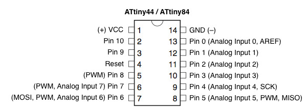
According to the datasheet, the microcontroller ATtiny44 can support up to 4 servo motors and the regulator 5v SMD provide well regulated power supply without low drop output current capacity.
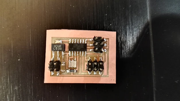
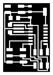
Heroshoot of the board hello.servo.44
Follow the making of the pcb board milling and welding process in this week (week 04)
Program
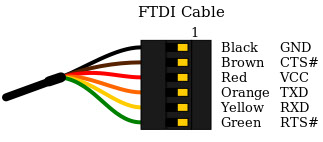
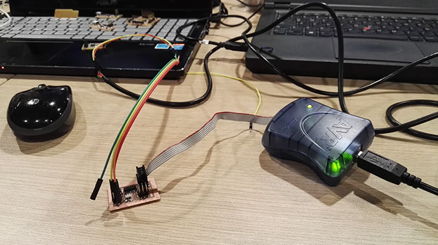
Connect the AVRISP mkII to the hello.servo.44 board and FTDI cable (5V), the AVRISP who writes the data on the hello.servo.44 board and the FTDI cable is used used as a transmitter of data to the computer and as a power supply.
sudo make -f hello.servo.44,make program-avrisp2
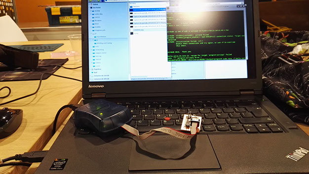
Remember to connect FTDI cable to the board as a power supply (I forget it, but I fixed it), because I can't flash it correctly without it.
Ready for flash the hello.servo,44. Then download the hello.servo.44 code
Open the terminal in ubuntu and write this code for flash the hello.servo.44 board.
sudo make -f hello.servo.44,make program-avrisp2
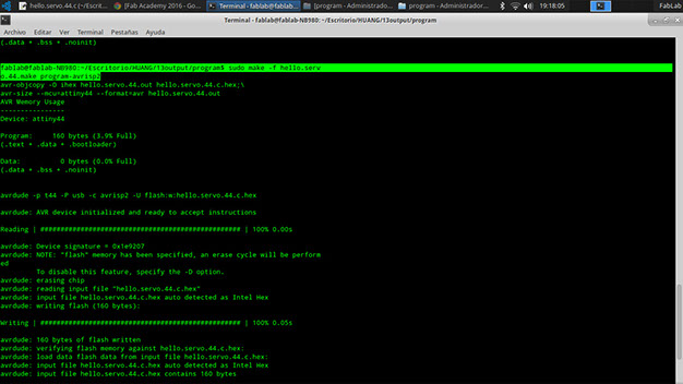
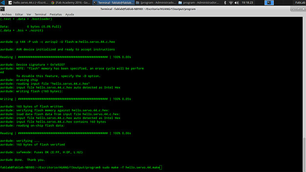
Screenshot of the flash verified
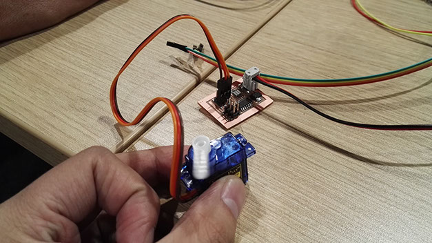
Disconnect all the wires, the FTDI cable not support 5v stable energy, so connect a battery of 9v to the GND and VCC pins; and connect the servomotor to the GND, VCC and SIGNAL.

GIFT of the servomotor working
Learning outcomes
- Demonstrate workflows used in circuit board design and fabrication
- Implement and interpret programming protocols
Have you
- Described your design and fabrication process using words/images/screenshtos.
- Explained the programming process/es you used and how the microcontroller datasheet helped you.
- Outlined problems and how you fixed them
- Included original design files and code
Download files
Copyright © Jorge Huang Li - FAB ACADEMY 2016