
INPUT DEVICES
WEEK 11
Task:
Measure something> add a sensor to microcontroller board that you have designed and read it
Tools and equipment:
- Milling machine: Roland MDX-20 mill
- Milling cutter: 1/64 for mill the circuits and 1/32 for cut the board
- Welding tools: Soldering iron stand, soldering wire and solder paste
- Multimeter
Software:
- Fabmodules
- Eagle
- Gimp
Temp Sensor
A thermistor is a resistive temperature sensor. Its operation is based on the variation of resistivity semiconductor with temperature. The term comes from thermistor temperature sensitive resistor. Two types of thermistor :
- NTC (negative temperature coefficient )
- PTC ( positive temperature coefficient )

Componets:
- Attiny 45
- Jack pin
- 3 x 10k Resistor
- NTC Temperature sensor
- 6 Header 6 FTDI
- 2x3 Header
- Capacitor 1uF
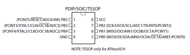
Datasheet
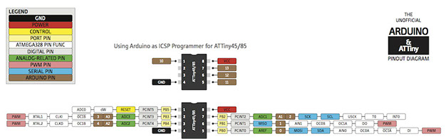
ATtiny45/ATtiny85 microcontroller is small and cheap that can run simple programs. The only disadvantage is that it has low memory to program many functions.
- Parameter
-
- 8 Pin count
- 4 kBytes of flash memory
- 256 Bytes EEPROM
- 256B SRAM
- 4 analog pin
Analog signal
An analog signal is a voltage or current which varies smoothly and continuously . A sine wave is an analog signal of a single frequency. Voltages voice and video are analog signals that vary according to the sound or variations of light corresponding to the information being transmitted .
Digital signal
Digital signals , in contrast to analog signals do not vary continuously, but change in steps or in discrete increments . Most digital signals use binary or two state codes.
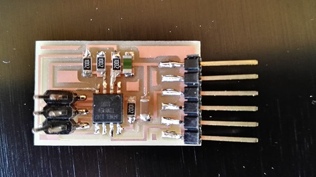
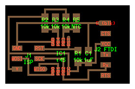
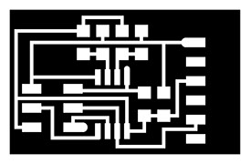
Screenshot of the temp board
Follow the making of the pcb board milling and welding process in this week (week 04)
Programming
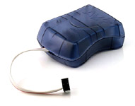
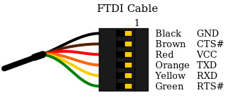
Connect the AVRISP mkII to the hello.temp.45 board and FTDI cable (5V), the AVRISP who writes the data on the temp board and the FTDI cable is used used as a transmitter of data to the computer and as a power supply.
Open the terminal in ubuntu and write the code for flash the hello board.
Ready for flash the hello.temp.45.make, then download the hello.temp.45.make code
sudo make -f hello.light.45.make program-avrisp2
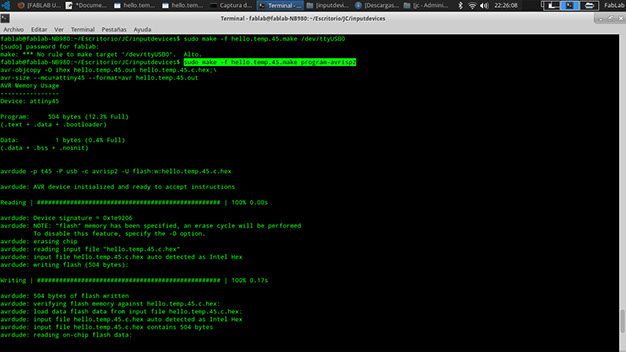
Screenshot of the flash verified
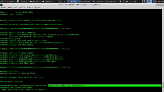
Open the terminal in ubuntu
Ready to run the python code for test the temp board, then download the hello.temp.45.py code
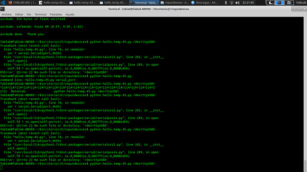
python hello.temp.45.py /dev/ttyUSB0
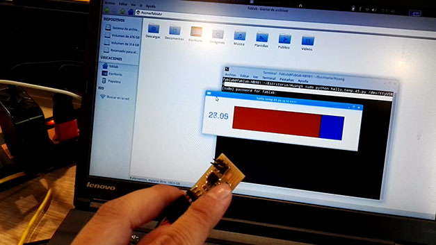
After to run the python code in ubuntu, the computer freeze, so for fixed it I made a test with a multimeter and the board has some welding problems FTDI connectors pins so I weld each componetn again for made a new test.
Learning outcomes
- Demonstrate workflows used in circuit board design and fabrication
- Implement and interpret programming protocols
Have you
- Described your design and fabrication process using words/images/screenshots.
- Explained the programming process/es you used and how the microcontroller datasheet helped you.
- Explained problems and how you fixed them.
- Included original design files and code.
Download files
Copyright © Jorge Huang Li - FAB ACADEMY 2016