
ELECTRONICS DESIGN
WEEK 06
Task:
- Redraw the echo hello-world board
- Add (at least) a button and LED ( with current-limiting resistor)
- Check the design rules, and make it
Tools and equipment:
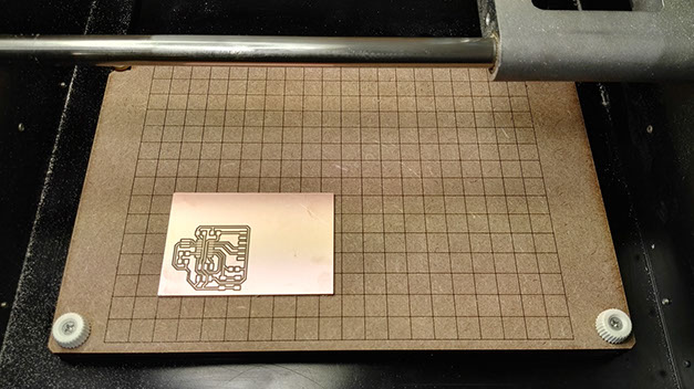
- Milling machine: Roland MDX-20 mill
- Milling cutter: 1/64 for mill the circuits and 1/32 for cut the board
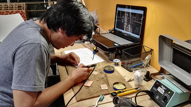
- Welding tools: Soldering iron stand, soldering wire and solder paste
- Multimeter
Software:
- Eagle
- Gimp
REDRAW THE ECHO HELLO-WORLD BOARD
- Eagle

Eagle is a free software diagramming program design and PCBs. Contains a wide variety of components that can be placed easily and then autorouter the ratsnest.
First step: Schematic drawing
- Follow the assignment tutorial: Intro to eagle
- Download and install the software: Eagle
- Download the libraries and paste in eagle directories:
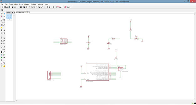
-
Components:
- Attiny44-ssu
- Resonator 20Mh2
- Resistor 499 ohm SMD
- 2 Resistor 10k ohm SMD
- Led SMD Yelow
- 6MM Switch : Omron switch
- Capacitor 1uf SMD
- Header 6 FTDI
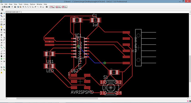
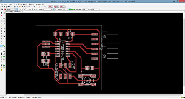
Second step: Route the traces on the board
- Menu/File/switch board
- "Move": Place the components properly
- Menu/Tools/autorouter: route all the traces and then redraw the traces manually if the traces intersect or "ratsnest" to junction the traces to the specific places.
- "Ripup": delete the traces
- "Route": Draw traces for avoid the junction
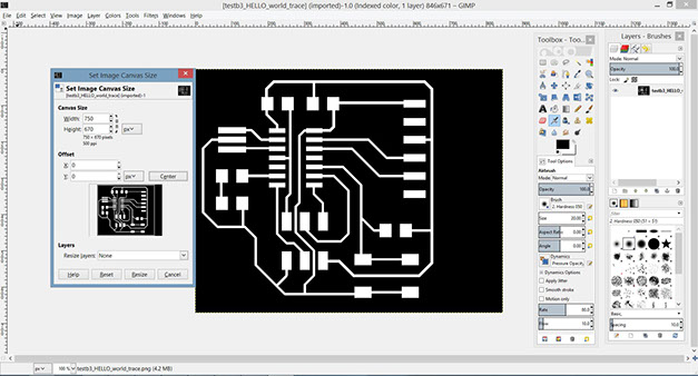
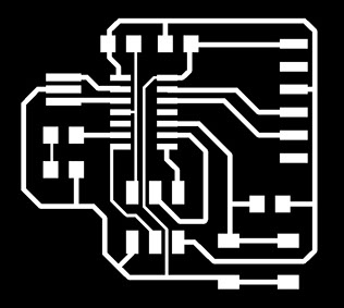
Third step: Export to create traces and mill files
- Menu/Layers settings: select only the traces layer (top)
- Menu/export/image: Browse the file directory, check in monochrome and resolution 500 dpi
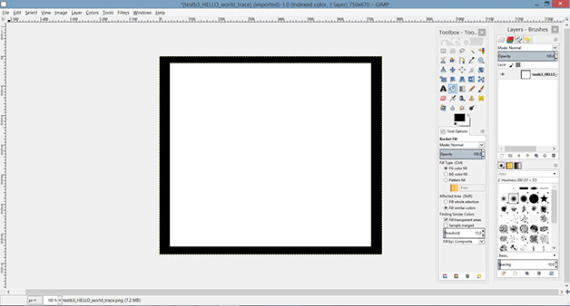
Fourth step: Canvas Size
- Reset canvas sizes to choose correctly work space
Fourth step: Create the interior (mill out)
Create an inner rectangle and paint it white, then use the invert and paint the black boundary
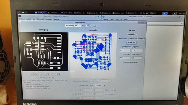
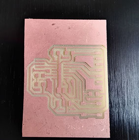
- Milling: Roland MDX-20 mill
Inside Roland software:
- Offset:4
- Error: 0.1
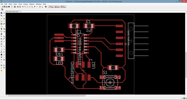
Eagle: Redesign the traces changing the width or thickness
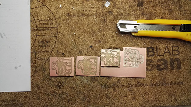
Modela: 3 broken milling cutter by settings and stick board
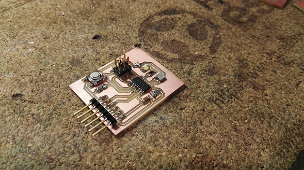
Fixed problems
Before to start to weld, the traces of the board are together because the line width of the traces in eagle has much thick. The minimum value of the drill is 0.02 and the width 0.01 in eagle.

Learning outcomes:
- Select and use software for circuit board design
- Demonstrate workflows used in circuit board design
Have you
- Shown your process using words/images/screenshoots
- Explained problems and how you fixed them
- Done fabbercise today
- Included original design files (Eagle, KiCAD, Inkscape - whatever)
Download files of week 06
Copyright © Jorge Huang Li - FAB ACADEMY 2016