Week 4: Electronics Production
For making the FabISP we need to:
-Mill the board.
-Solder Components.
-Programming the Fab-ISP
Making an In-Circuit Programming - Milling the board
-First, I downloaded the necesary files to work from http://academy.cba.mit.edu/classes/electronics_production/index.html
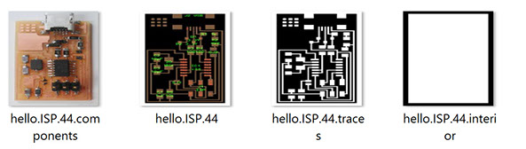
That design files are premade. The traces are the areas to be milled that will make up the paths" within the board, and the interior is just a design to cut the PCB board.
I will make the Fab ISP circuit board. The FAB ISP allows you to program the microcontrollers on other boards you make, using just an USB cable and 6-pin IDC to 6-pin IDC cable.
Besides the designs, you need the following:
- Roland MDX-20 Mill
- Single Sided Copper Clad Circuit PCB Board
- Double sided tape
- 1/64 and 1/32 Milling bits
- Fabmodules software.
The MODELA MDX-20/15 is an affordable, all-in-one scanning and milling device, perfect for a variety of product design tasks, from model and jewelry making to molds, rapid prototyping, small lot production and package design. Use it to test and modify your designs, reducing errors, time and cost.
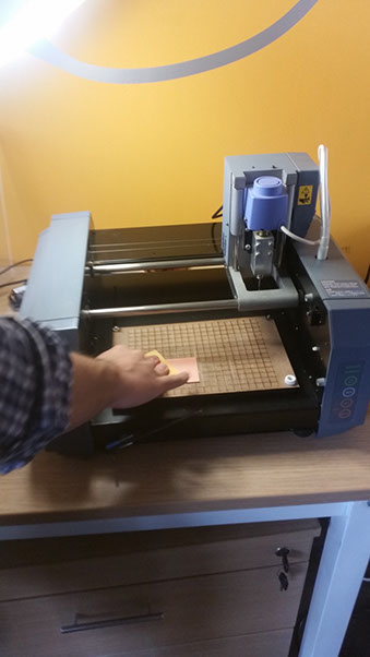
Befire milling, I applied pressure softly on the PCB board, to the sacrificial layer, so that it was adhered to it. The sacrificial layer is a MDF one, with laser engraved lines.
 After that, I opened fabmodules, that was already installed. First using the 1/64 mill for trace. Select ‘input format’ and then from the corresponding drop down, select image(.png), and load the PCB trace.The png image have to be in black and white, the white part determines your circuit.In the "Output process", select "Roland MDX-20.mill(,rml)"In the "With workflow" select "make_png_rml".Next, set the origin for the PCB miller or CNC. I had to set the XY origin, using the "Move to xmin ymin" option en the fabmodules. This would move the milling head to that point. And for adjusting the Z measure, it was adjusted repeatedly looking until the mill scratches the board just a few.
It was important to know about the controls of the Roland MODELA:
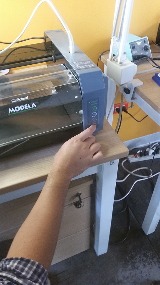
- The Green power button, controls the power to ON/OFF
- The View button, moves the cutting head away, so that you can see your cutting surface.
- Tool Up, moves the cutting head up. This is for setting the z-axis.
- Tool Down, moves the cutting head down. This is for setting the z-axis.
Milling the board: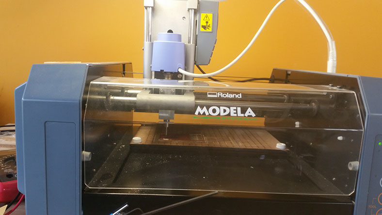 I had some problems with the milling cutter, It was broken during the process.
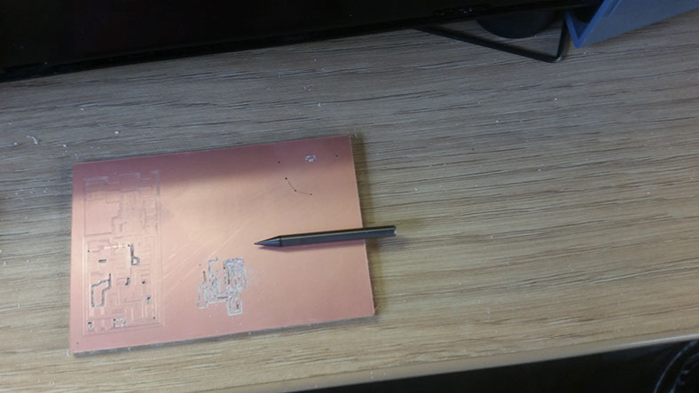 The milling cutter was not properly adjusted to the milling machine. Or the milling machine was trying to mill too deep, because I adjust the z measure, not when the mill barely touchs the board, but pushed 3 times more, because of somebody advice. The lesson: while adjusting the z measure, just wait until the mill barely touchs the board. After that, somebody wanted to save some stick tape, and cutted the board, just in the area neccessary for the circuit design. It was not a good idea, and the board has moved during the milling process. Not enough area sticked.When things went right, this is the final result:
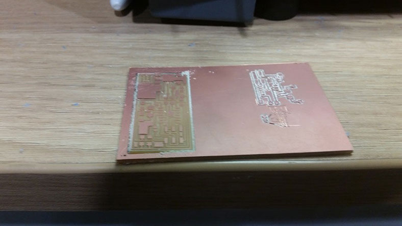
Making an In-Circuit Programming - Soldering Components I downloaded the FabISP labeled board diagram, to see what components I need, and where to place them on the board. I made a list of the components: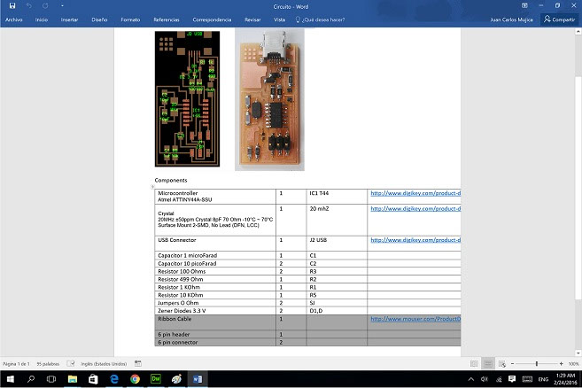
I solder the components to the board using a soldering iron and solder paste, begining with Microcontroller Atmel ATTINY44A-SSU, and the 6 pin header, because they are the most difficult ones to solder. After that, I solder the other components. Because of the size of some components, they dont have a layer to identify them, so its very useful to do something like this, to identify each component: 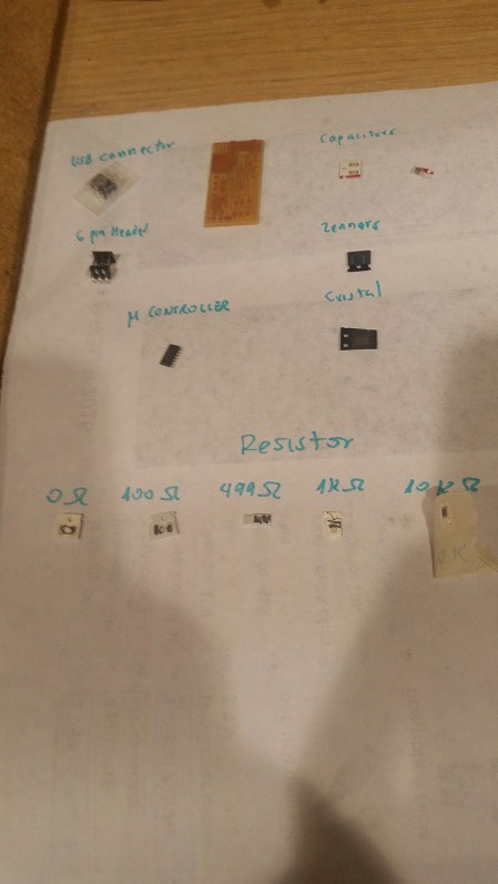
The final result, including the connector: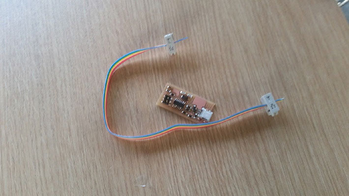 I tested it to see if it worked. Everything was good according to the green light (any short circuit was detected).
 Making an In-Circuit Programming -Programming the FAB-ISP
Download files:
firmware
Download the firmware http://academy.cba.mit.edu/classes/embedded_programming/firmware.zip, and put it in a directory of the PC
Download drivers, or verify they are already installed in ubuntu terminal:
apt-get install flex byacc bison gcc libusb-dev avrdude
apt-get install gcc-avr
apt-get install avr-libc
apt-get install libc6-dev
Download the make file,and edit it to change the programmer, instead of avrisp2, I used the avrispMKII, in the following line
AVRDUDE = avrdude -c avrispMKII -P usb -p $(DEVICE) # edit this line for your programme
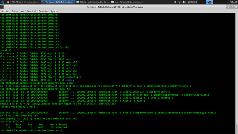
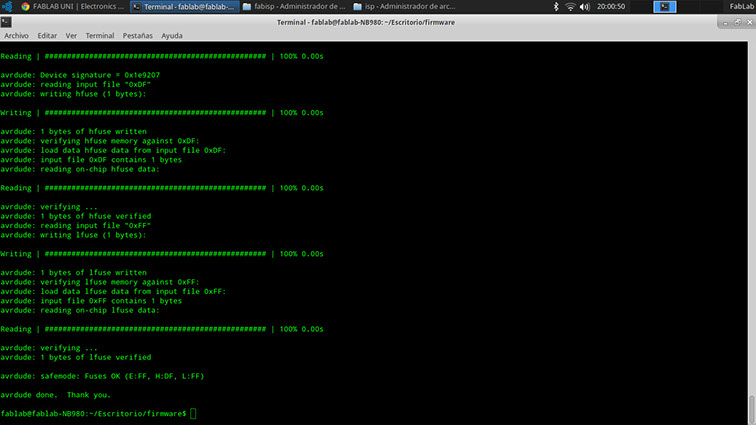
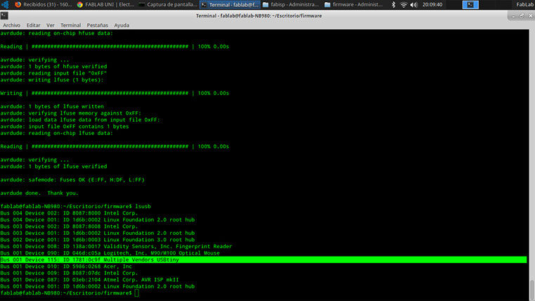
I programmed the Fab-ISP following the commands secuence, in the terminal of Ubuntu. -make clean-make hex-sudo make fuse-make program
The final result, the message "Multiple Vendors USBtiny" appears.
References:
http://fabacademy.org/archives/2015/doc/programming_FabISP.html
http://fab.cba.mit.edu/content/projects/fabisp/
http://diyhacking.com/pcb-milling-tutorial/
http://fablabuni.edu.pe/electronics-production/
http://archive.fabacademy.org/archives/2016/doc/programming_FabISP.html