Two Processors talking
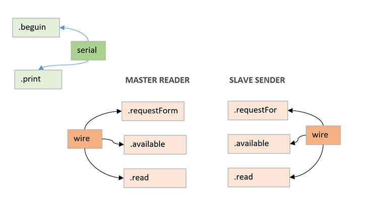
In this example, two boards communicate in a Master Reader/Slave Sender configuration using the I2C synchronous serial protocol.
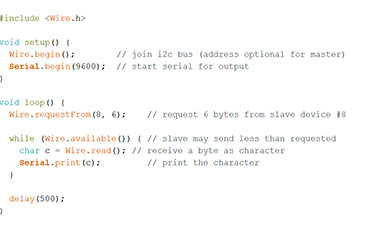
Arduino's Wire Library s needed. The Master, is programmed first to request, and then read, 6 bytes of data sent from the Slave Arduino.
With the message received, it is shown in the Arduino Software (IDE) serial monitor window.
I arrange this configuration:
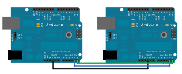
The I2C protocol involves using two lines to send and receive data:
- A serial clock pin (SCL) that the Arduino or Genuino Master board pulses at a regular interval.
- A serial data pin (SDA) over which data is sent between the two devices.
A bit of information is transferred over the SDA line in each clock pulse. The sequence of the bits are: the adress of a specific device and a command or data. The destination device executes the request and transmits it's data back to the board over the line using the clock signal generated by the Master on SCL.
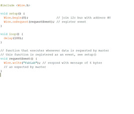
That is what the sketches of the master as the slave contains.
I tried to replace one Arduino whit a Fabduino, but it didnt work. I was trying to find out about the reason, checking specially the pins SCL and SDA, ATMEGA 328 have in pins PC5 and PC4. I couldnt find the reason why didnt work.
Concludings / Recomendations
The I2C protocol, allows for each device in a comunication, to have a unique address, and to comunicate taking turns, but in a single line. So its posible to extend this shem to many devices to be comunicated.