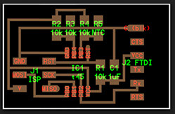
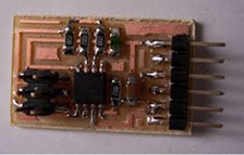
In FabAcademy Web page, is detailed how to build a temperature board. You can see it here.
But the example found in that page, is firstable programming the board, so that it is reading the temperature and the sending via his Rx pin (Tx pin is isolated, as shown in the following figure).
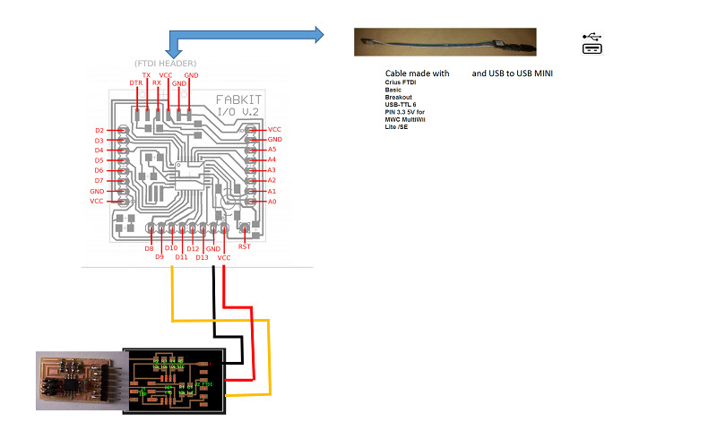
Whit that board already programmed, it is possible for Fabduino to read it. So the connections, and the components to connect are shown below
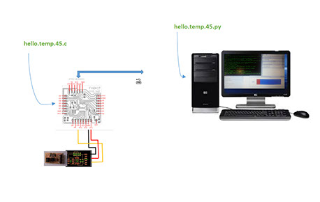
To build the program I analized the examples in the Fabacademy web page:
hello.temp.45.c (the c language program to read temperature and send data)
hello.temp.45.py (the python program that receives data from the board already programmed with the c program)
Analizing the python version, how does it recieve data:
byte2 = 0
byte3 = 0
byte4 = 0
ser.flush()
while 1:
#
# find framing
#
byte1 = byte2
byte2 = byte3
byte3 = byte4
byte4 = ord(ser.read())
if ((byte1 == 1) & (byte2 == 2) & (byte3 == 3) & (byte4 == 4)):
break
low = ord(ser.read())
high = ord(ser.read())
value = 256*high + low
if (value > 511):
value -= 1024
V = 2.5 - value*5.0/(20.0*512.0)
R = 10000.0/(5.0/V-1.0)
# NHQ103B375R5
# R25 10000 (O)
# B (25/85) 3750 (K)
# R(T(C)) = R(25)*exp(B*(1/(T(C)+273.15)-(1/(25+273.15))))
B = 3750.0
R25 = 10000.0
T = 1.0/(log(R/R25)/B+(1/(25.0+273.15))) - 273.15
filter = (1-eps)*filter + eps*T
x = int(.2*WINDOW + (.9-.2)*WINDOW*(filter-20.0)/10.0)
canvas.itemconfigure("text",text="%.2f"%filter)
canvas.coords('rect1',.2*WINDOW,.05*WINDOW,x,.2*WINDOW)
canvas.coords('rect2',x,.05*WINDOW,.9*WINDOW,.2*WINDOW)
canvas.update()
parent.after_idle(idle,parent,canvas)

The programm made in processing language for Arduino uses the same logic as the python version one of the Academy .
#include <SoftwareSerial.h>
// Conectar el pin 10 del arduino al Rx del board
SoftwareSerial Serial1(10, 11); // RX, TX
unsigned char byte1, byte2, byte3, byte4;
unsigned char low, high;
int value;
float V,R,R25=10000.0, B=3750.0, T;
void setup() {
// put your setup code here, to run once:
Serial.begin(19200);
Serial1.begin(19200);
}
void loop() {
// put your main code here, to run repeatedly:
byte2=0;
byte3=0;
byte4=0;
Serial1.flush();
while(1)
{
byte1 = byte2;
byte2 = byte3;
byte3 = byte4;
byte4 = Serial1.read();
//Serial1.read();
Serial.print("byte4");
Serial.println(byte4,DEC);
if( (byte1==1 ) & (byte2==2) & (byte3==3 ) & (byte4==4) )
{
Serial.println("break");
break;
}
}
low = Serial1.read();
high = Serial1.read();
value = 256*high + low ;
Serial.print("value: ");
Serial.println(value);
if(value>511)
value -= 1024;
V = 2.5 - value*5.0/(20.0*512.0);
R = 10000.0/(5.0/V-1.0);
T = 1.0/(log(R/R25)/B+(1/(25.0+273.15))) - 273.15;
Serial.print("temp: ");
Serial.println(T);
delay(500);
}
Running the program, the results in the serial monitor are:
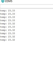
You can see Fabduino reading a the temperature board and showing the tempertaure in the Serial Monitor.
Fabduino reading the temperature board (hello.temp.45).