Machines used and softs:
CNC: CIF Technodrill
Software: Galan, Perceval,Fabmodules, Eagle,Kicad...
Using the CIF
For the moment I wasn't able to use a CNC from the inventory (like a Roland MDX 40) but in the future I will mill all my boards using the Fabmodules and a machine from the inventory.
So first we need to prepare the machine:
Put the correct tool
Tape the PCB on the plate
Fix the X,Y and Z axes
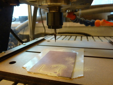
I had some issues with importing the GRB file to Galan , so to get may hands on the machine I justed tried to mill a random circuit that was already converted:
And finally I understood that I just needed to open the file on Eagle and then export it to Galan.
So I could start milling the correct circuit:
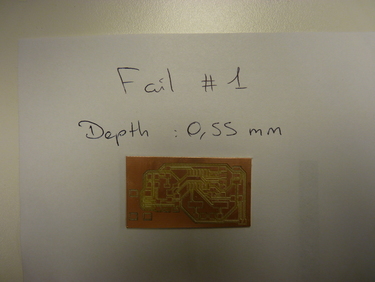
Here I had set my engraving depth to 0.55mm which was too much, the tool was totally eating my circuit.
So I did an other test using the multimeter technique for the Z axis:
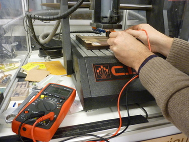
What I did is once we have an electrical contact, I know that the tool is just touching the surface, so I checked on Google to see the thickness of the cupper surface of a PCB ,which is 350 microns, and I added that value to my Z.
The job started perfectly but my tool brocked (don't buy cheap tools!)
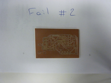
I finished the job just to see the final result but I knew that it wouldn't be ok.
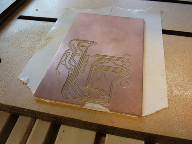
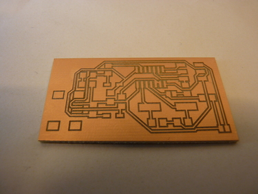
Finally I changed the tool, did the same proces and got this result:
I decided to take advantage of working in the FABLAB of the University Pierre and Marie Curie to learn about the chemical etching.
In UPMC there are ways of taking care of wasted chemicals but that isn't the case in FABLABs, so I will not explain the process, but just show you the final result:
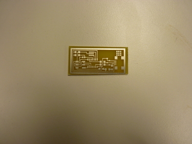
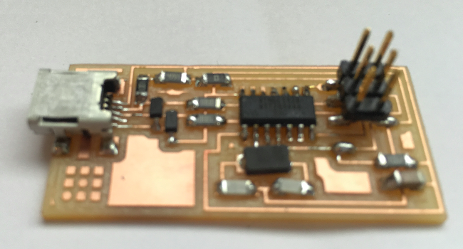
There was a simple error caused by the contour which was made to small and so it touches the pin for the USB, but that can be fixed with a cutter.
Here are all the files for the board:
Eagle: fabisp.sch fabisp.brd
Schematic: fabisp.pdf
Programming the FabISP ( on UBUNTU)
General inspection and "Smoke test"
Before pluging the board, we want to do a visual inspection of it, to be sure they are no electrical issues ( Short circuits ...) , and once we plug it in, keeping a finger onto the chip, lets us feel if the chip overheats.
Setting up
The first step is to upload the firmware to the FabISP, this will indicate to the chip how it has to work. Becose for the moment it is just a bunch of components soldered together.
It is like a computer that has no BIOS.
To do so we need to download some things in order to communicate with the chip.


We can see that everything went find:
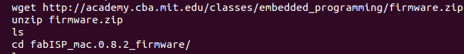
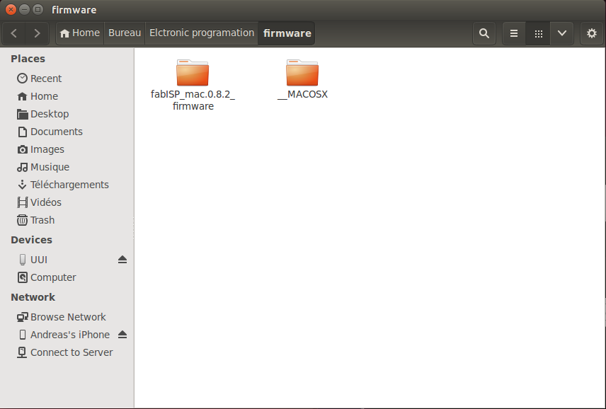
Now we need to download the actual firmware, here is the file : firmware.zip
Or you can to it in the terminal:
Using an other FabISP for the programmation
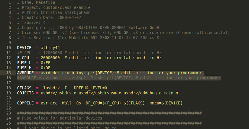
It is possible to use a second FabISP to program the one I just made, in order to do so, we just need to change 2 lines in the Makefile located in the Firmware file:
Comment the line "avrdude -c avrisp2..." and uncomment the line "avrdude -c usbtiny..."
The firmware is now ready to be loaded into the FabISP.
Programming
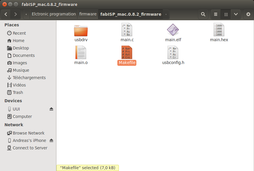
We need to open a terminal in the file where is located the firmware:
The prgramming is achieved by typing a series of cammand, I will first indicate the command and then the repsonse that the terminal gave me :

This is the reposnse we were waiting for:

Next command:

You may obtain different values:
Gererally this is where you can obtain errors, with the "fuse" command, I will talk about what happened to me in the Troubleshooting .

If you get a series of "writing" and "reading" that succeeded, this is a good sign that your chip is working properly.
If you are lucky this may work on the first shot, if not you will have to go true some troubleshooting like I did.
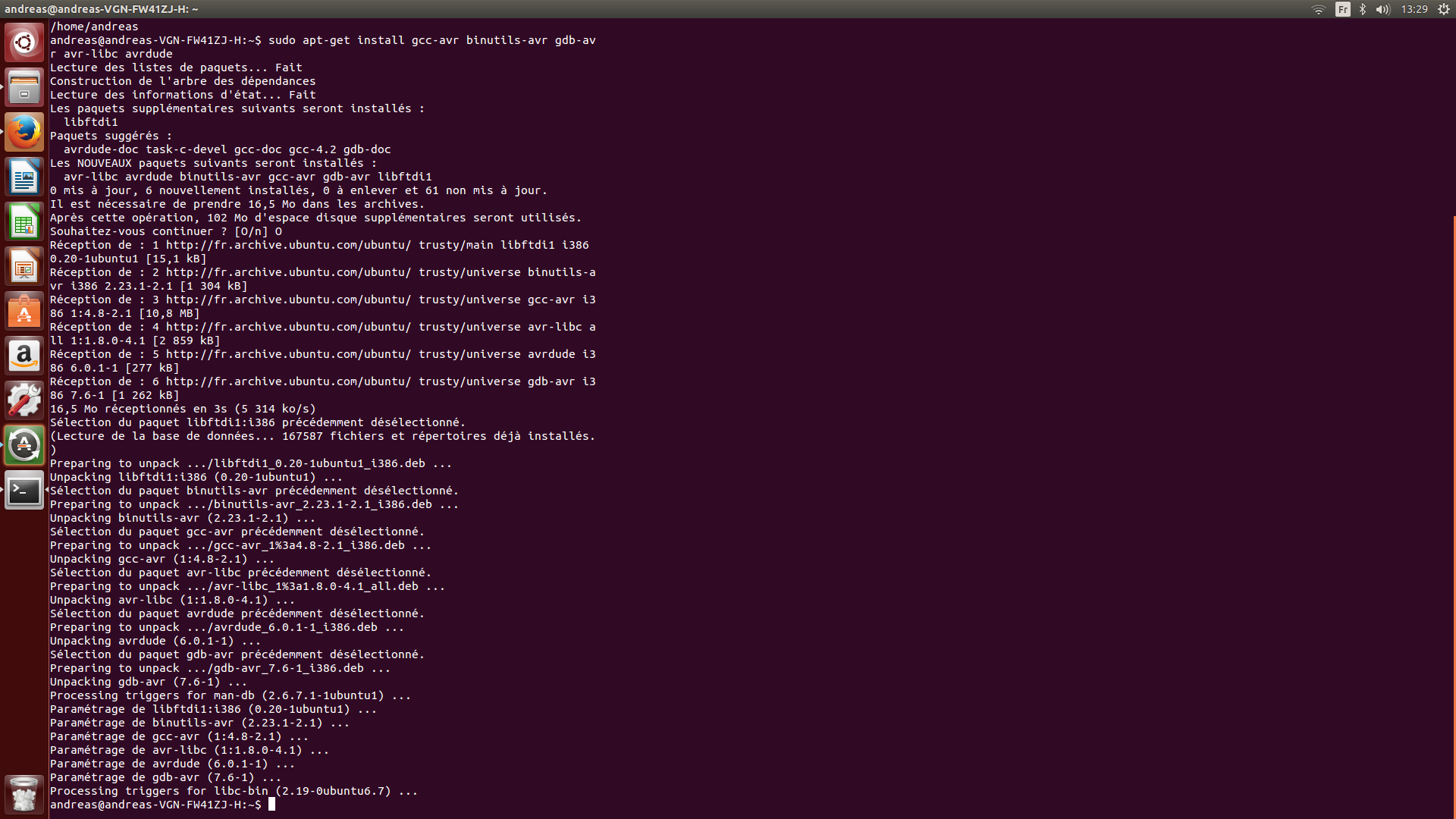
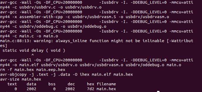
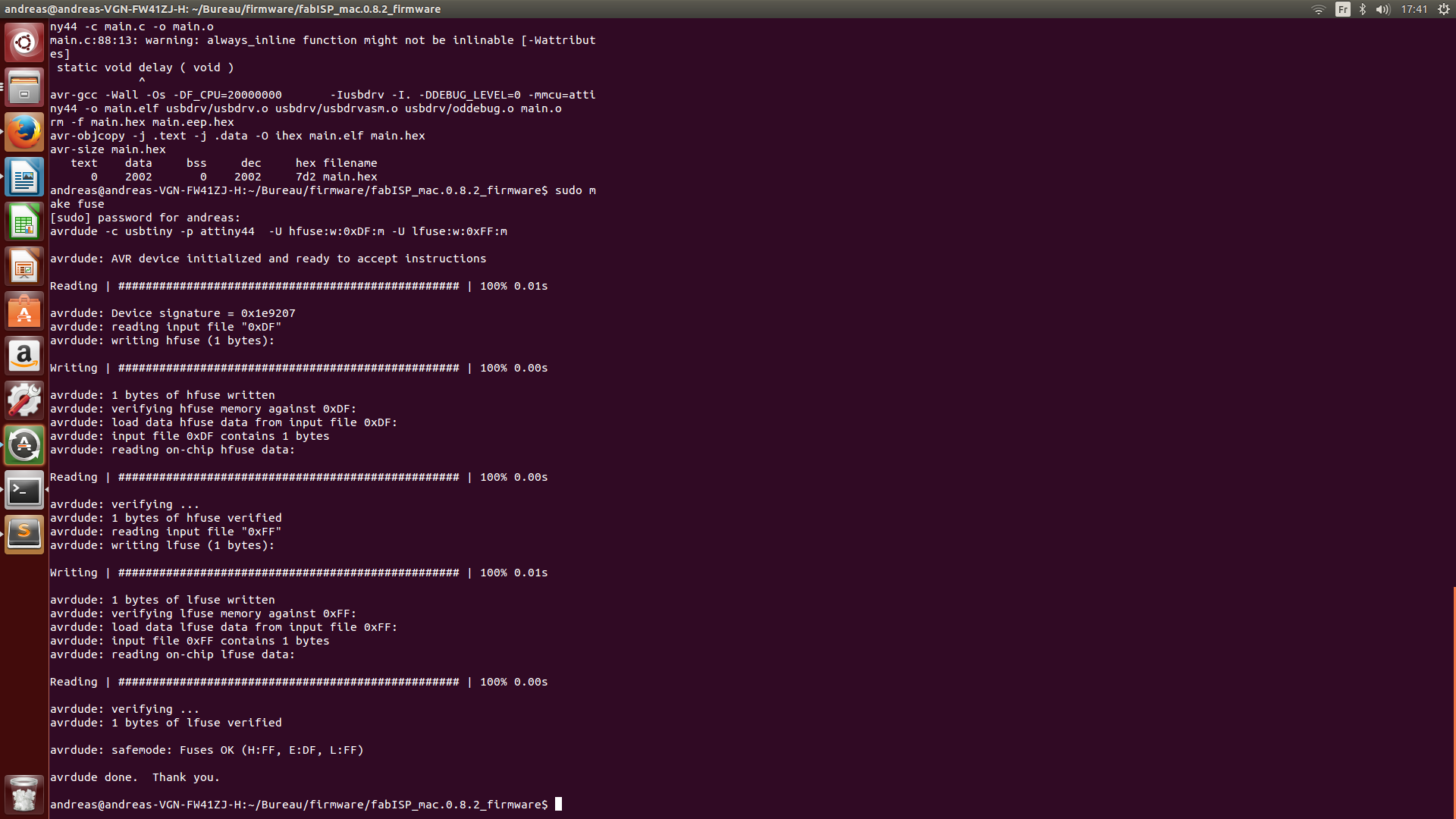
And last but not least, we know have to finally load the firmware on the FabSIP, the is achieved with the "make program" command:
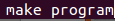
And this is what the screen of victory looks like (in the mean time my computer died so I proramed it with an other computer as you can see on this terminal):
You can see that 2002 bytes have been written and verified onto the chip, they correspond to the firmware that now is into the USBtiny.
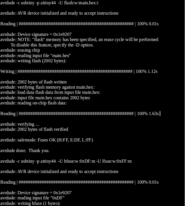
We can perform a last check to verify that our board is recognised by the computer, we simply connect the FabISP with a USB cable and type the command "lsusb" :

We can see that the USBtiny appears on the Bus 006:
It took me a while to get to this point (Troubleshooting) so I was pretty happy!

So know I have a fully operational FabISP:

General troubleshooting
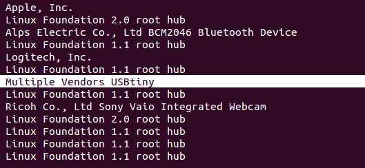
Its starts with a general inspection of the board and reflowing any solder joints that look cold (not smooth and shiny)
Then using a multimeter, check all the connections, making sure that Vcc and GND are not shorting, and that all the components are well soldered.
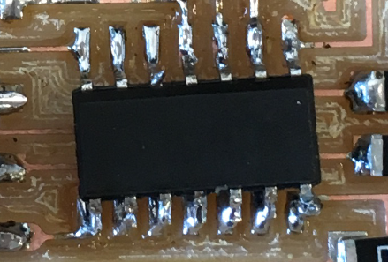
Check for bridges , especially on the USB connector and and the ATtiny.
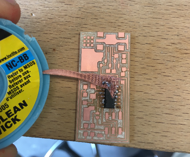
Use flux and desoldering braid to remove the solder and disconnect the bridges.
Still not working?
I knew I had a problem because when trying to run the "make fuse" command, I had this :

Since I had verified all my connections I thought it was a software problem, so I installed Avrdude and GCC again, just in case:
Type:

Then:

Press "y".


I also tried running all the progrmmaing commands as root but didn't change anything.
My instructor told me it could be one of the components that was dead, especially the ATtiny chip which I had re-touched a couple of times.
When I was about to go mill a new board and start all over again , I decided to give it a last try, the ATtiny was tricky to solder so I knew if there was a problem somewhere it would be with that component.
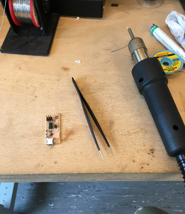
So I changed my tools :
And de-soldered the ATtiny cheap by simply holding my board by the chip and gently heating the ATtiny until the board felt.
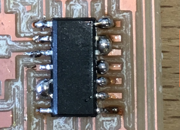
I replaced the same component and used the soldering iron to resolder one pin, and used the heat gun to resolder the rest of them in an instant:
The chip is not even well aligned with the pins, but we can see that the connections are smooth and shiny
I then retried to program the board, and it actually worked! Thinking that I almost threw away the board!