This week's assignment was to build a machine with moving parts. Since our lab has recently begun 3D printing prosthetic hands for the eNable Community Foundation, I thought it would be a great idea to mechanize one of the hands. Unlike the prosthetic design, though, in which all fingers move simultaneously when the wrist is bent, I wanted each finger to be able to move independently.
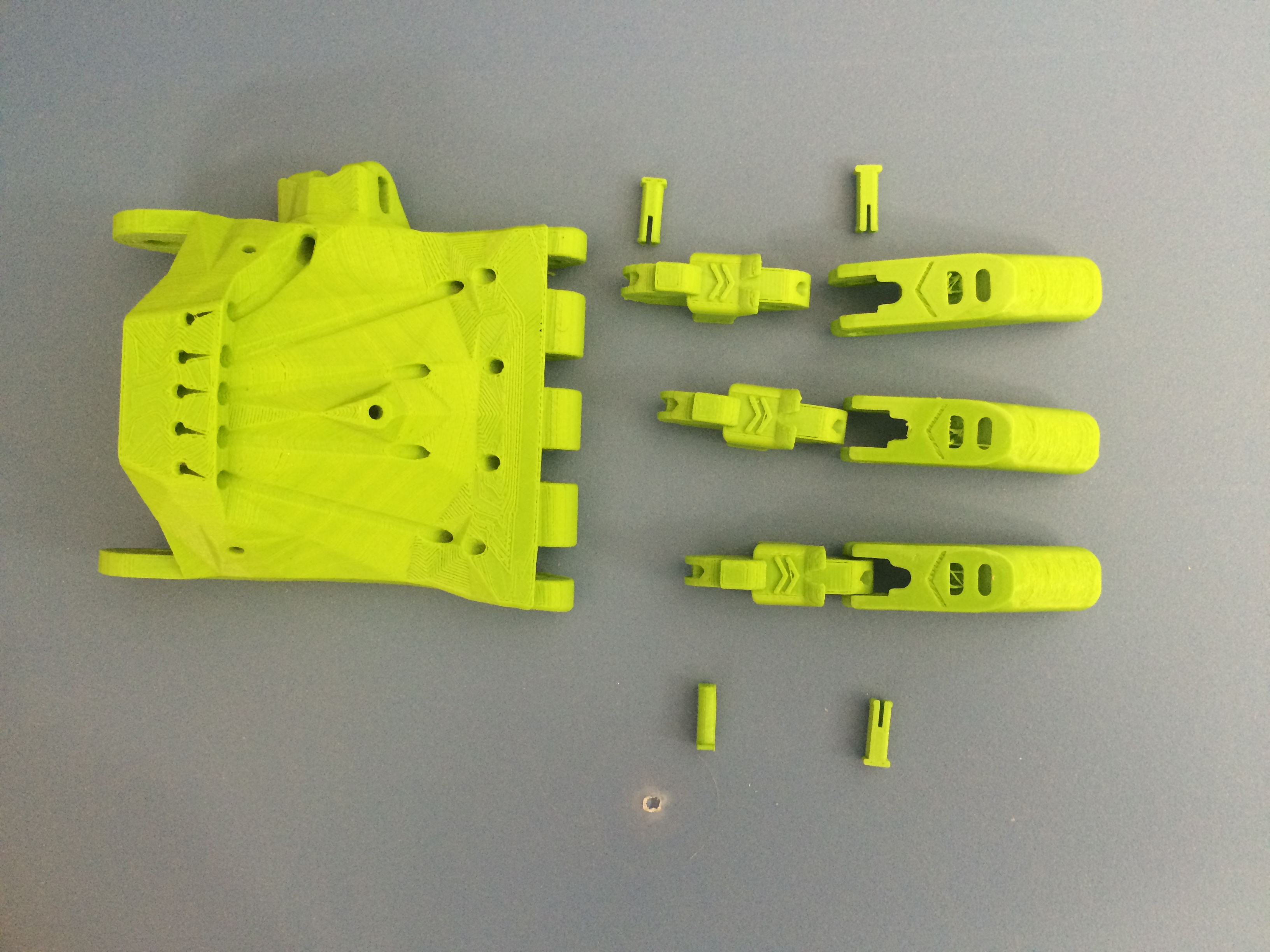
The first thing I did was print the entire design. I printed it at a small size so that I could fit it all on one print bed (I have an Ultimaker 2). I also removed the wrist, since I didn't need it to make my demo hand. After 22 hours of printing, I had to sand and file the parts off the the support.
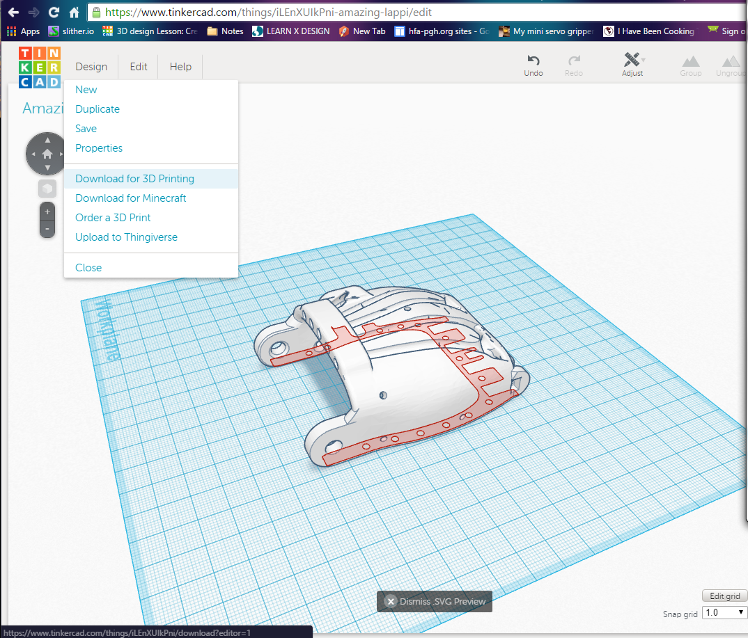
Next I had to mount the hand on a surface. I wanted the hand to sit straight up on the board, so I needed to design a mounting board and an upright piece to fit in the palm. Since the palm is an odd shape, I used the 3D design on Tinkercad to get the exact shape of that part. With just the palm piece of the hand on the surface, I clicked preferences>download for 3D printing> download laser cutter plans.
 <
<
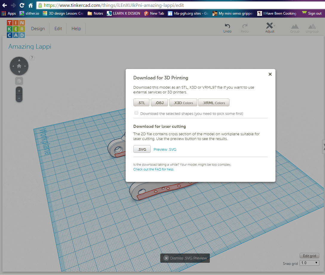
This method allowed me to download just the base of the palm piece, and it saved as an svg file on my computer. I opened it up in Coreldraw and I did a lot of work with the node editing tool inorder to try and remove the outside of the piece and the holes.
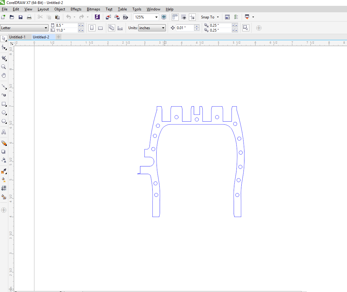
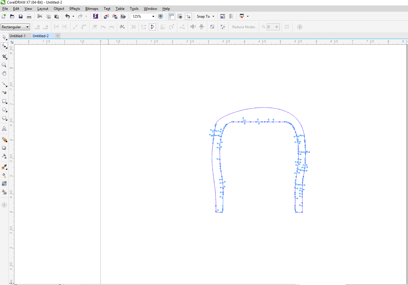
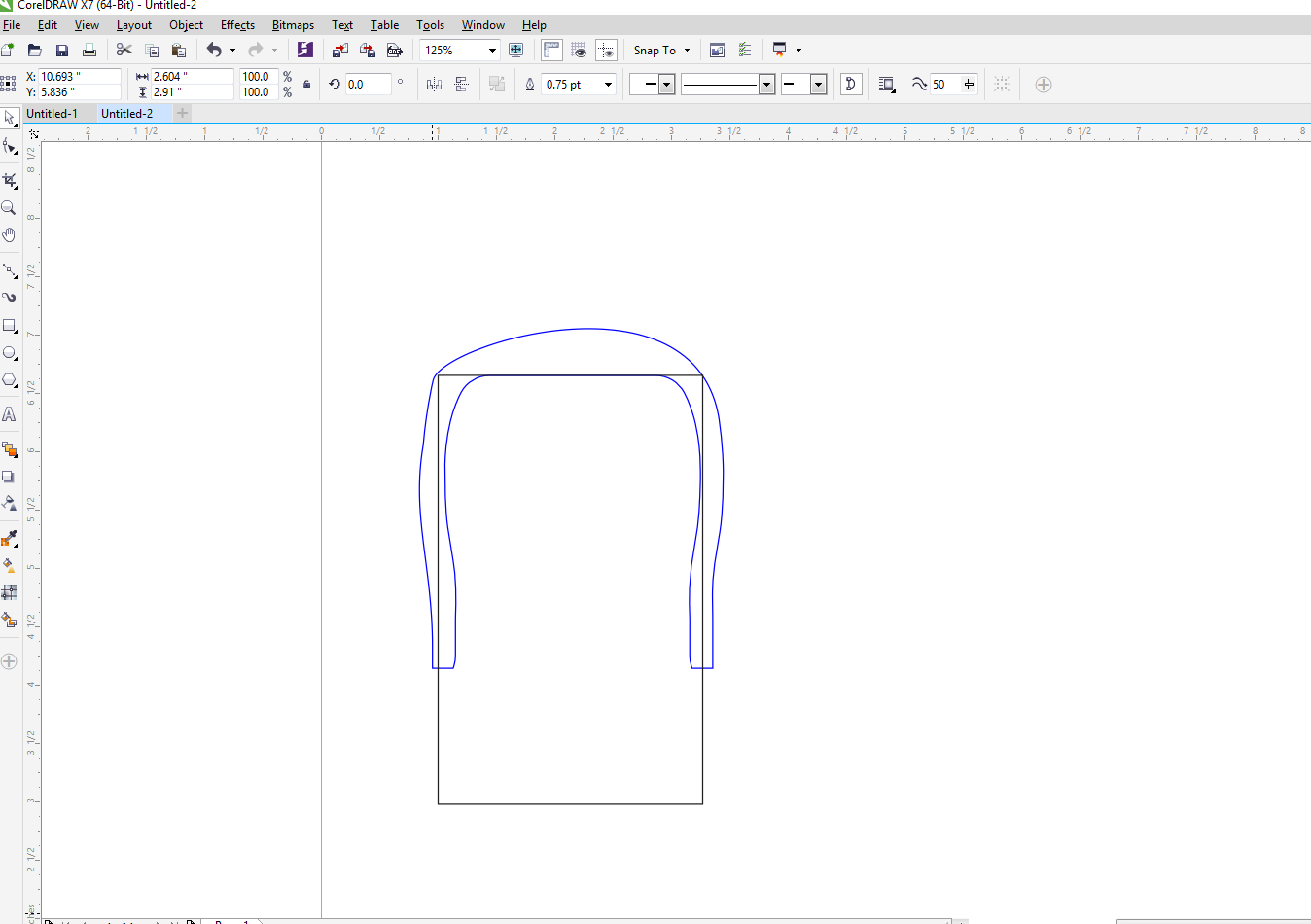
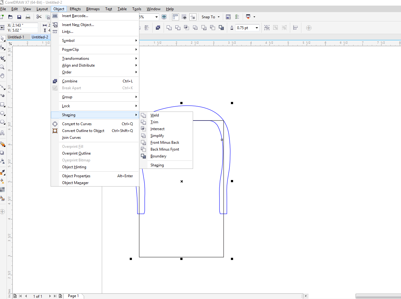
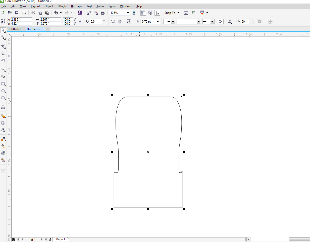
Just editing the nodes wasn't getting me where I wanted, which was having the inside curve of the original shape as the outside curve of th new shape (which I would cut out of wood). So, I figured out that I should draw a rectangle shape in front of the palm shape and then combine the two shapes using the menu
Object>Shaping>Back minus Front
That worked fine, and the finished file is here.
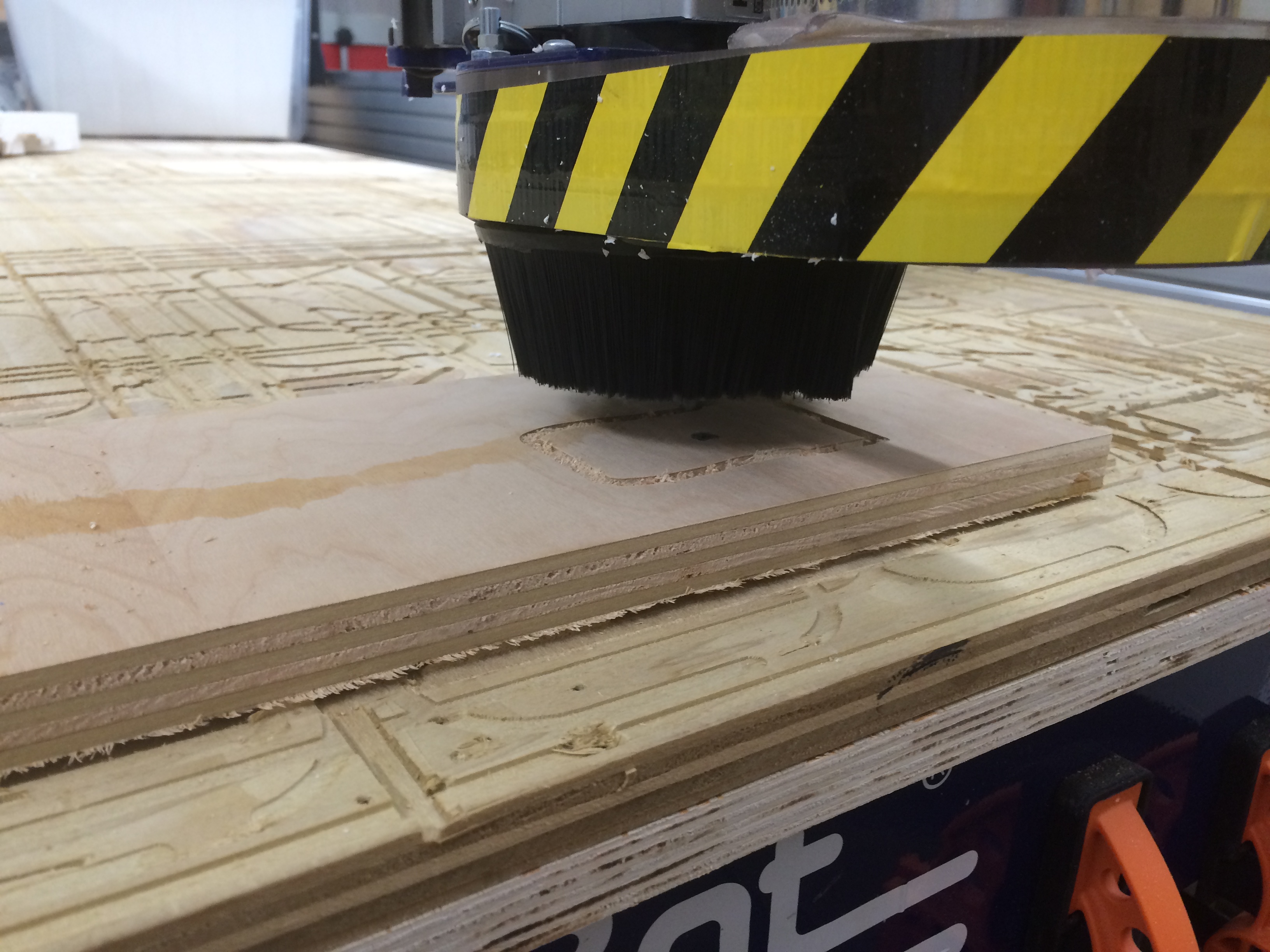
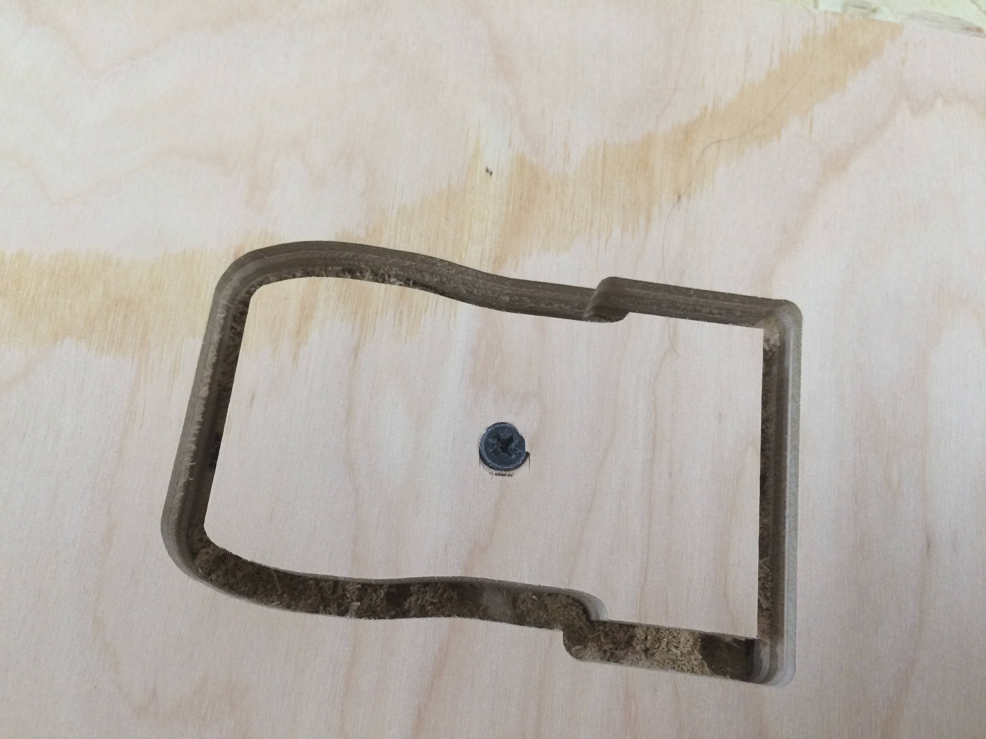
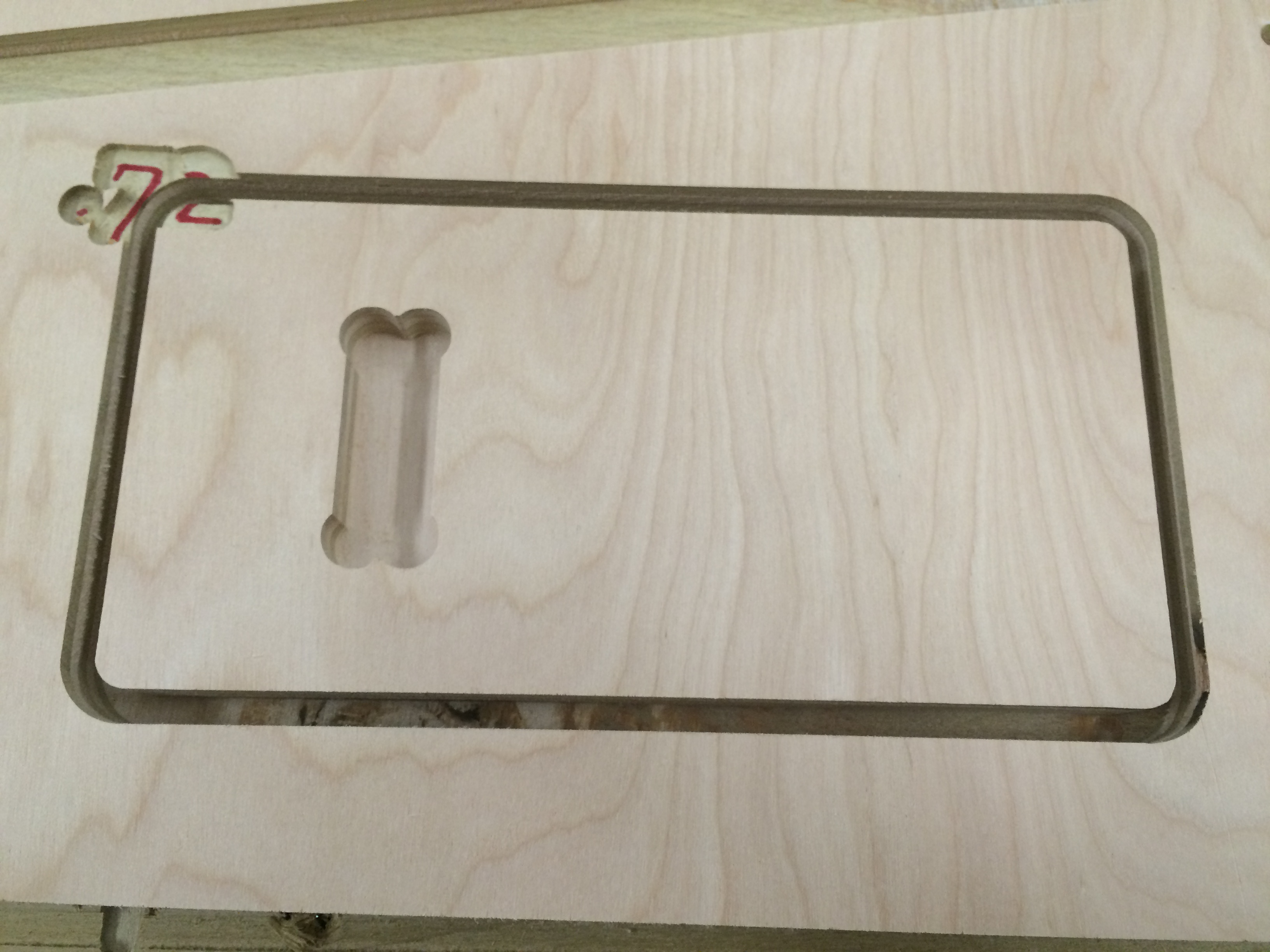
Once I had the shape that I wanted, I imported the svg file into VCarve, and I set a profile toolpath. I had in a 1/4" 2 FL bit, and so I set the toolpath to cut along the line. I also added in a drill holes toolpath in order to set a place for me to manually put in a screw before the profile path was cut. I worried that since this was such a small piece, it would move about once it was free and ruin the cut.
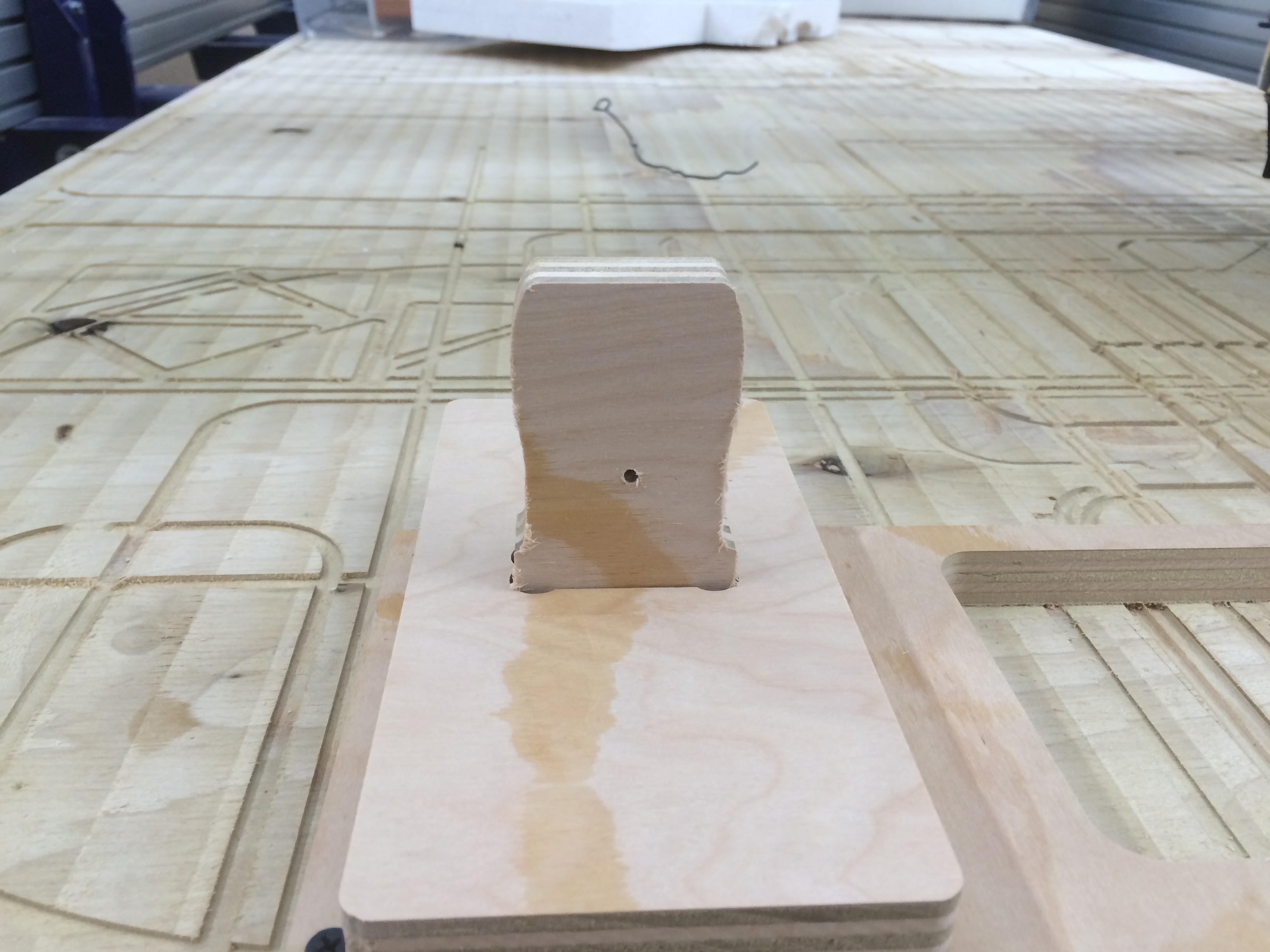
I tested the fit on the palm support in the palm, and it was a nice fit.
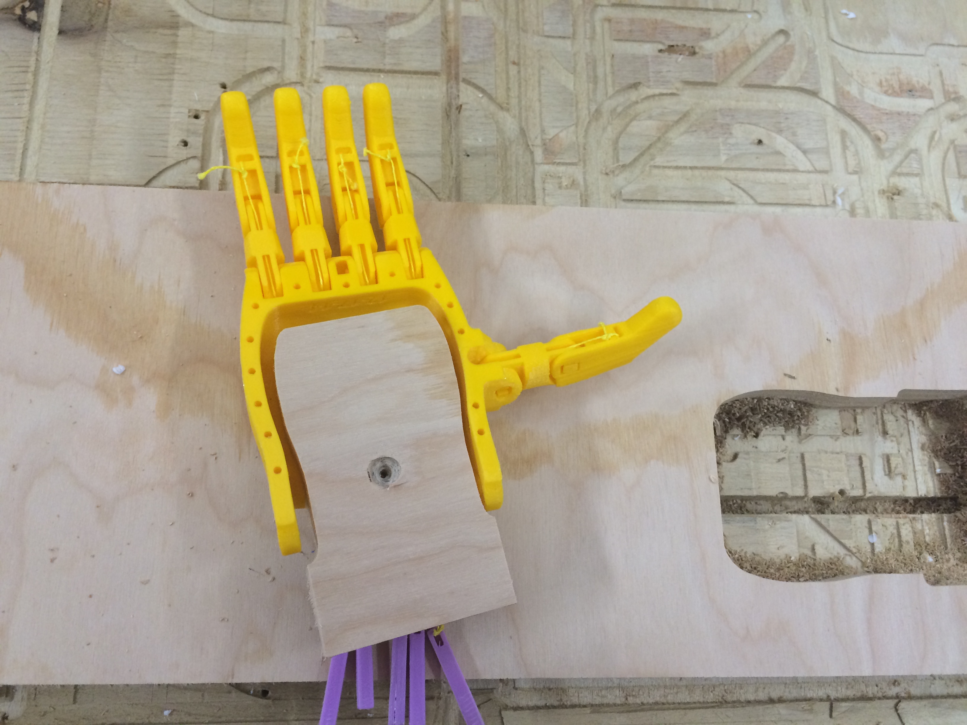
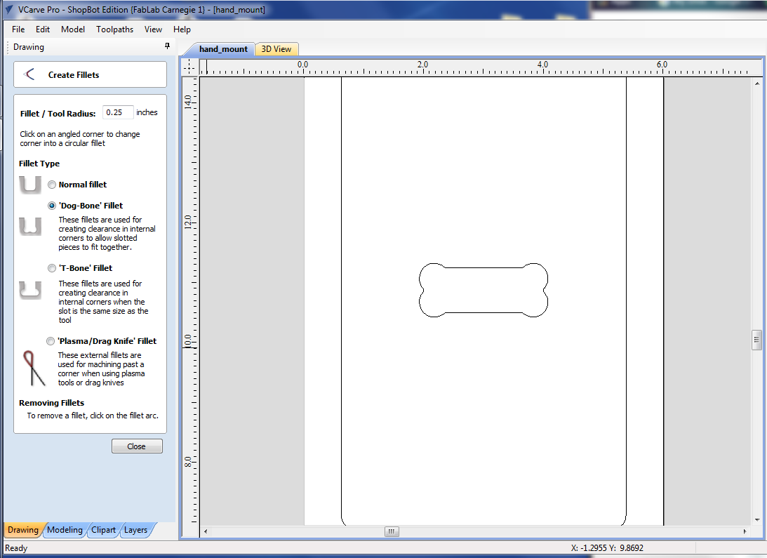
Next I designed the base that would hold this piece upright, so I needed to design a pocket and a board. The pocket had to fit this piece into it nicely, so I was very careful with my measurements, and I added fillets in the corners with the filleting tool, so that the bit could reach into the corners. I made sure that my fillet/tool radius size was set at 0.25".
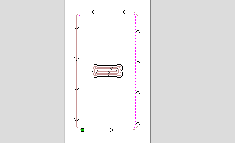
Then I set a profile toolpath for the base shape to cut, and I assembled it. My palm support piece fit nicely in the slot on the base.
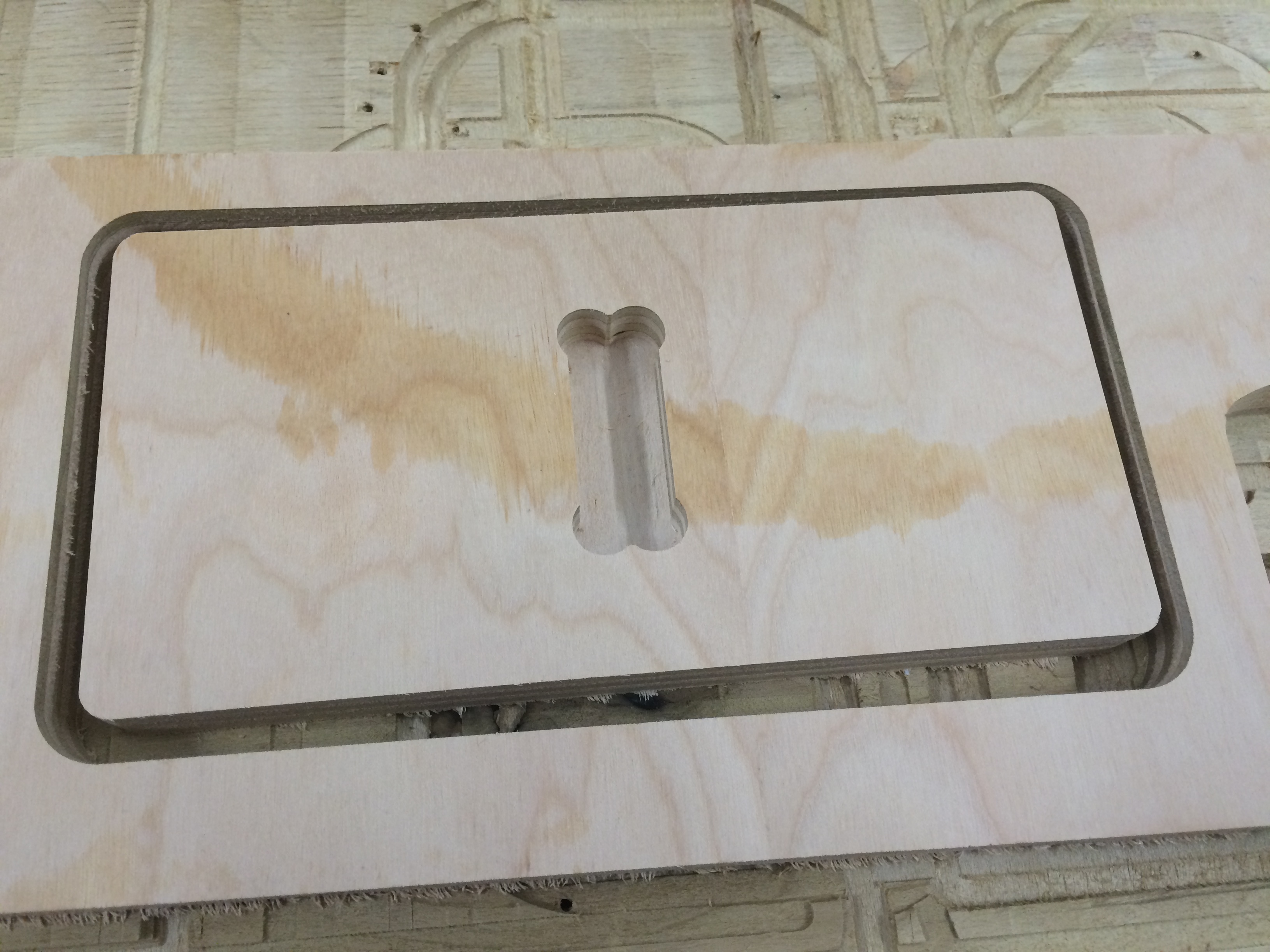
Once I had my base assembled, though, I realized that I needed more room on onoe side of the slot to mount my servos, so I cut a new piece, moving the slot closer to one end of my base.
My final VCarve design file can be found here.
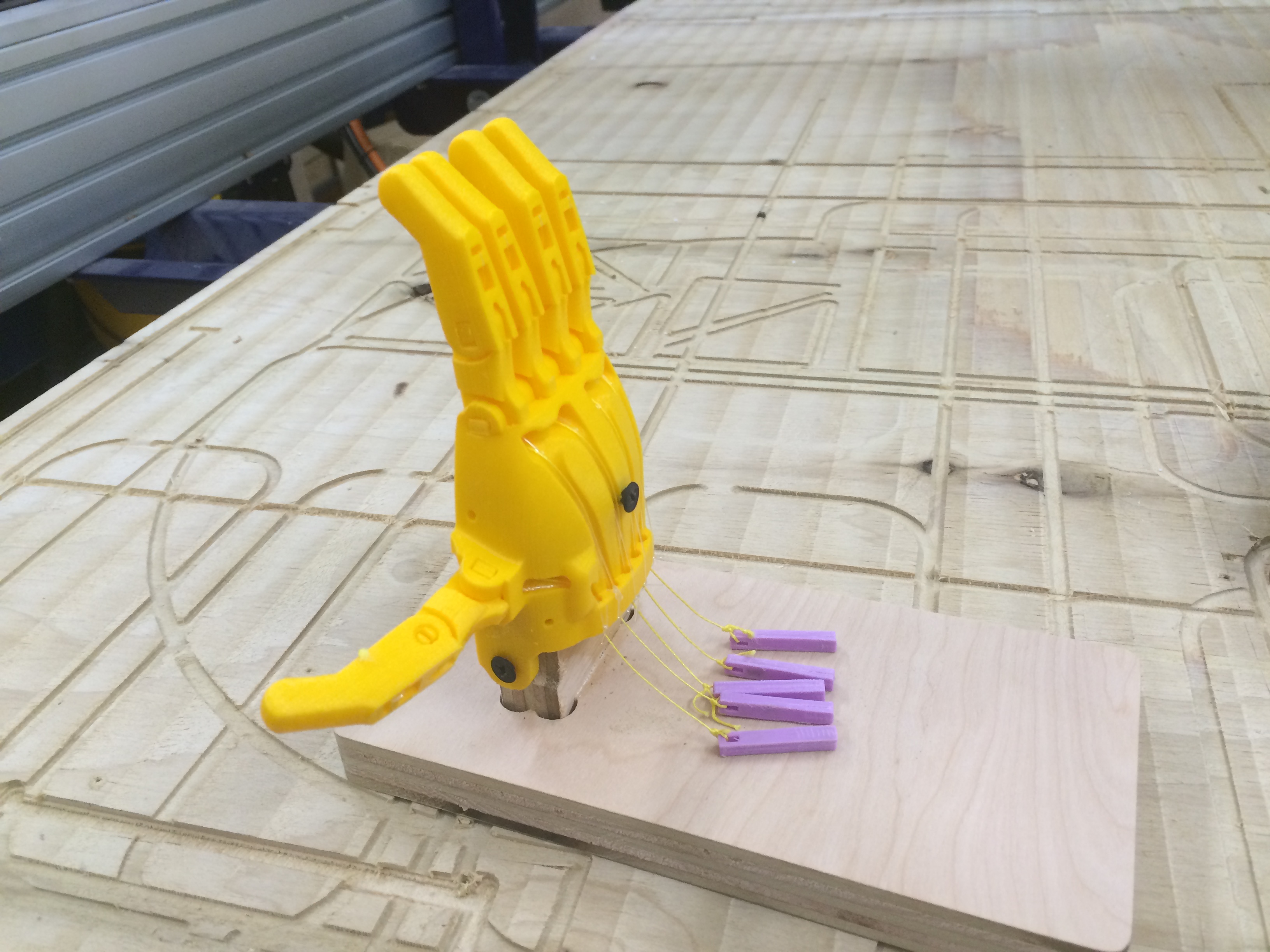
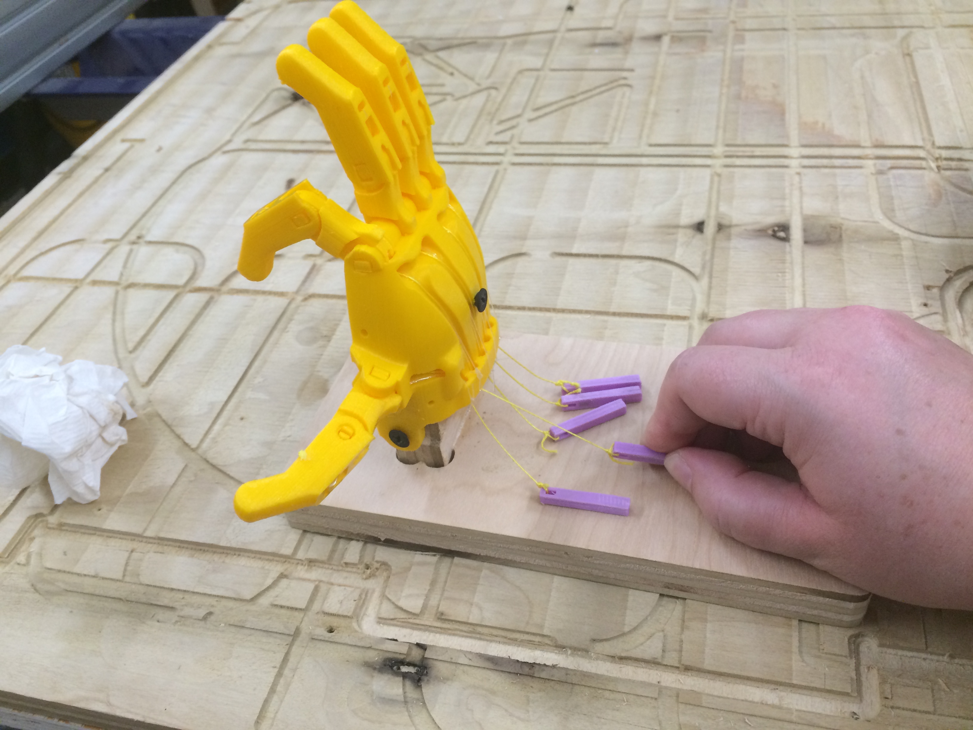
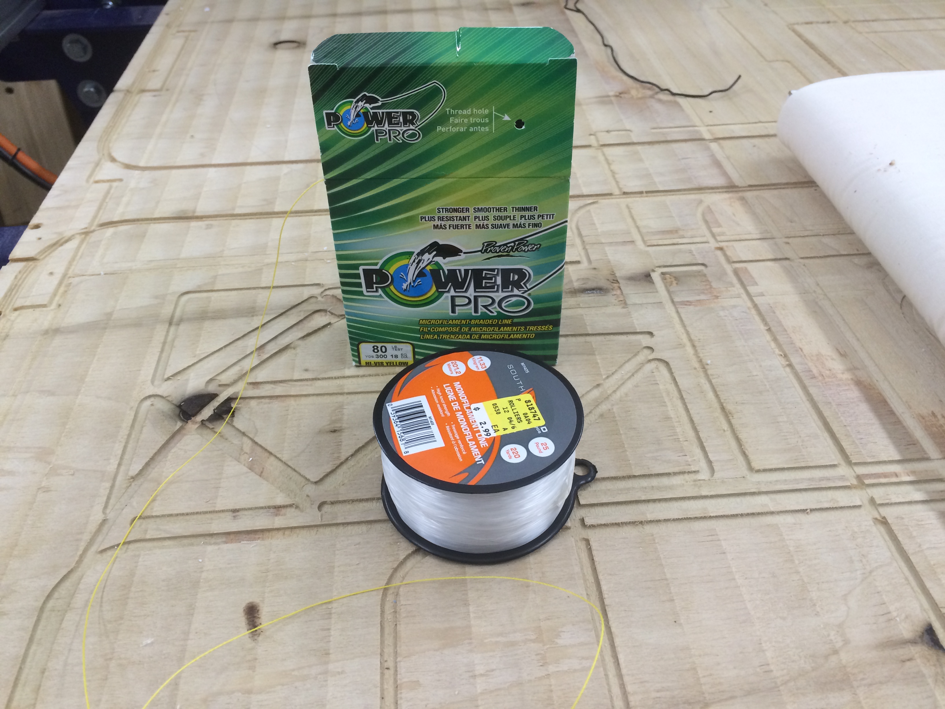
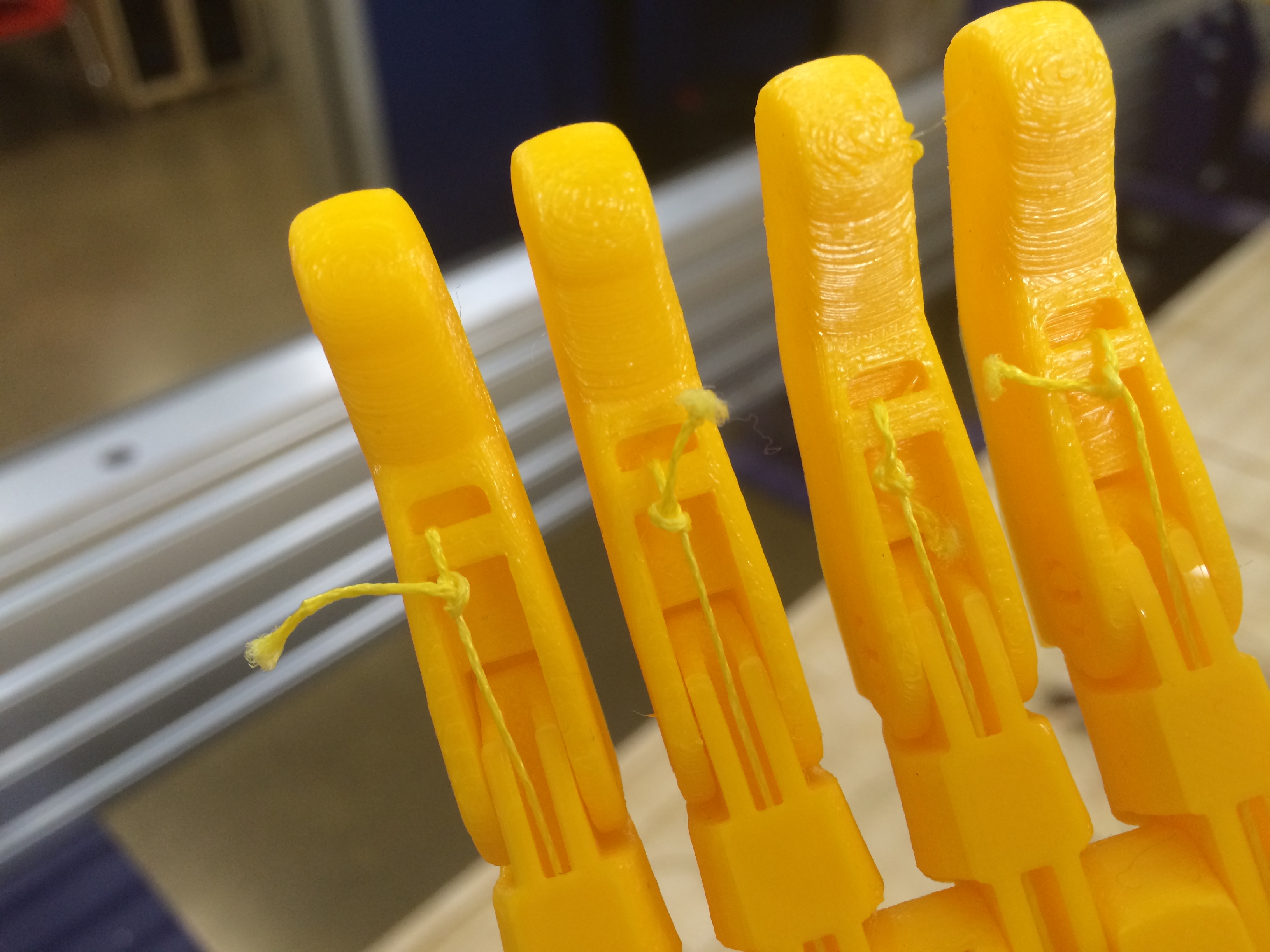
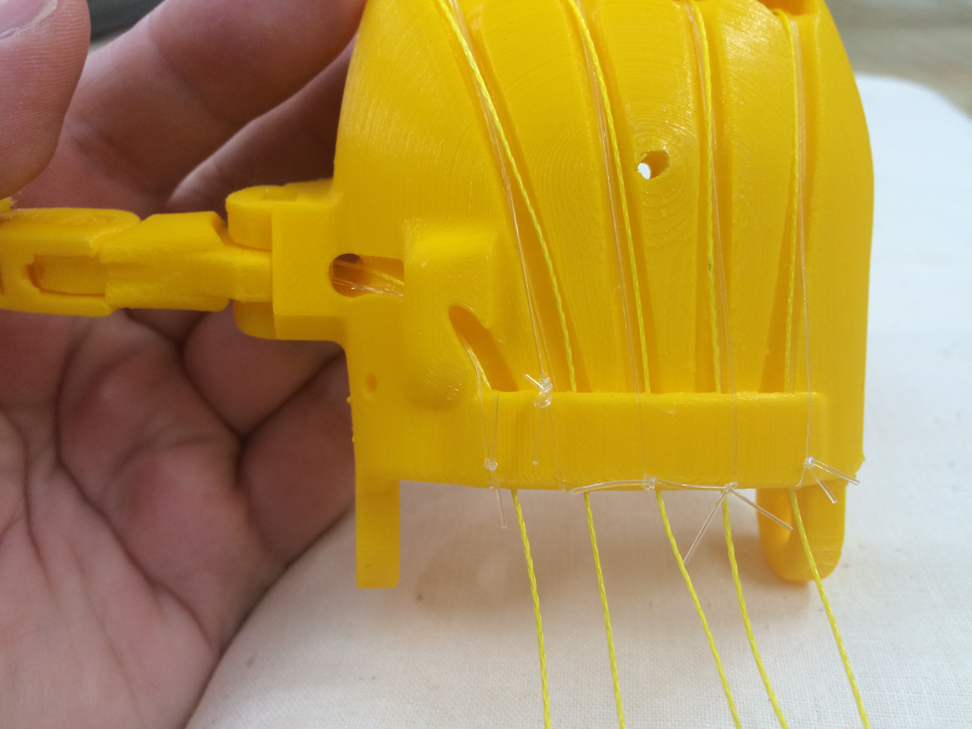
Next I had to string the "tendons" in the hand. Then tendons are what pulls the digits closed, so I used a very strong fishing line, which is the yellow string. I had to carefully string it through the channels along the back of the palm pieces, and inside of the fingers where I had to tie it to the tips. In order to keep the fingers upright when there is no pressure on the tendons, I used a stretch elastic fishing line (the clear one) which I tied to the bottom of the palm piece and just the first finger section.
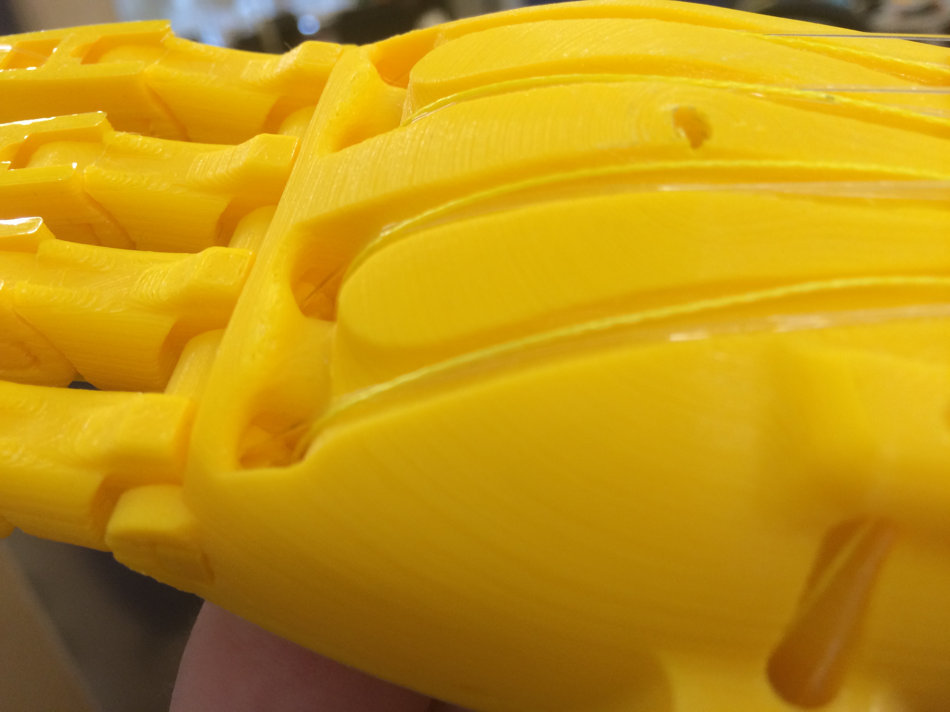
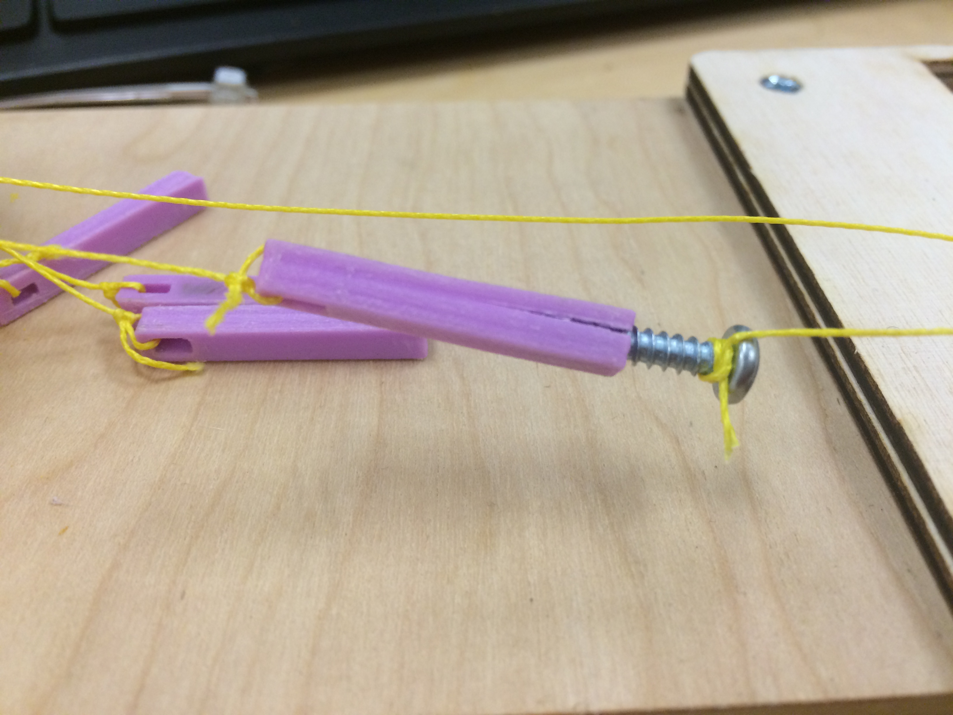
In preparation for adding servos, I added tensioner rods that I printed out as well. I broke a few of these during assembly because of the screw size being wrong, but eventually I got it worked out so that once the string is tied to both ends, you can screw in the screw to shorten the tensioner rod.
This is the full hand demo machine assembled.