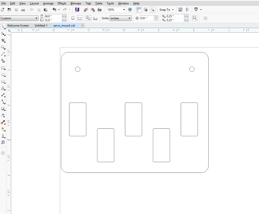
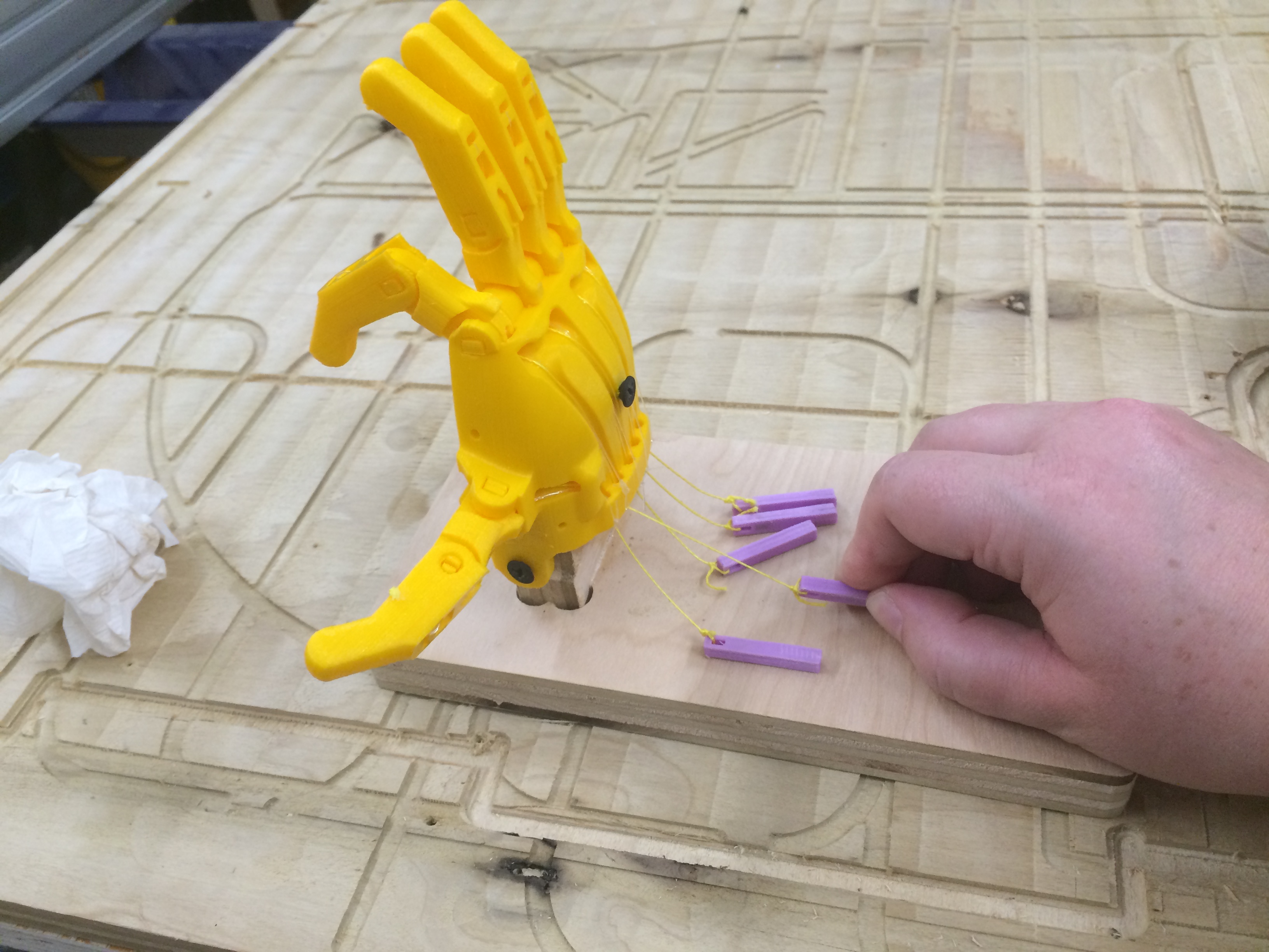
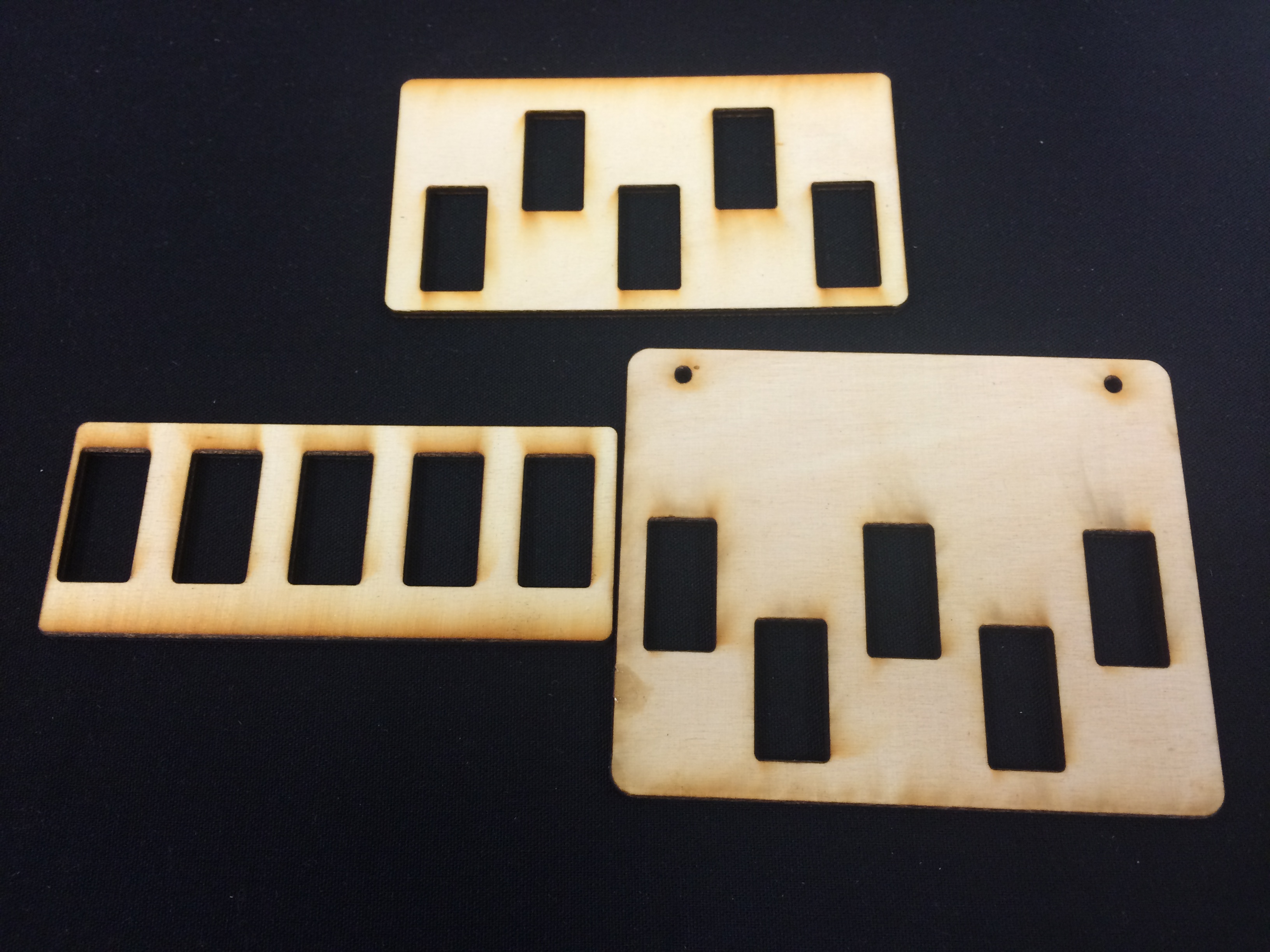
Once I had the hand printed, mounted, and functional using your hand to pull the strings attached to each finger, I was ready to integrate servo control. The first thing I did was design a servo mounting board which attached easily to the base using two screws. I cut two of these boards on the laser cutter so that I could double the thickness and have a pretty tight fit for the mini servos that I used.
I had to make a few iterations before I found a good size for the cutouts.
First, I tried testing a button to run the servo directly through the Arduino board. (I was having trouble with my fab ISP, so I thought it would be quicker to run it on an Arduino Uno.)
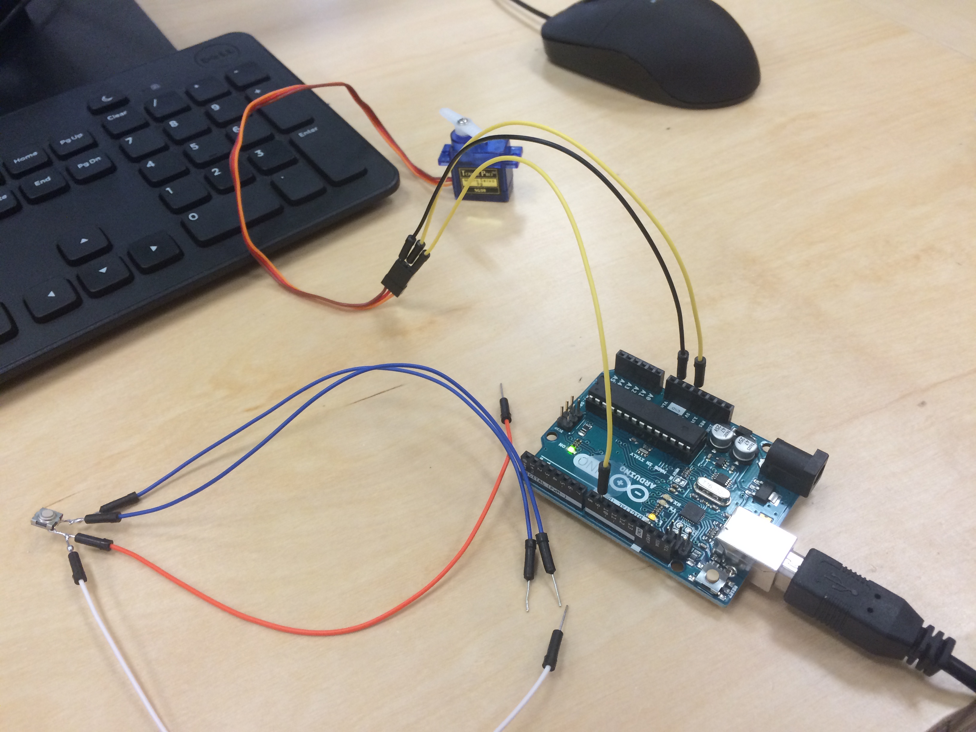
This wasn't working because the button was inline with the servo, which would essentially just turn on the servo in short bursts. What I needed was for the board to sense when a button push happened and then send a signal to the servo to change positions.
I did some internet research.Here are some tutorials I looked at when I was figuring out how to wire up and program a servo controlled by a push button.
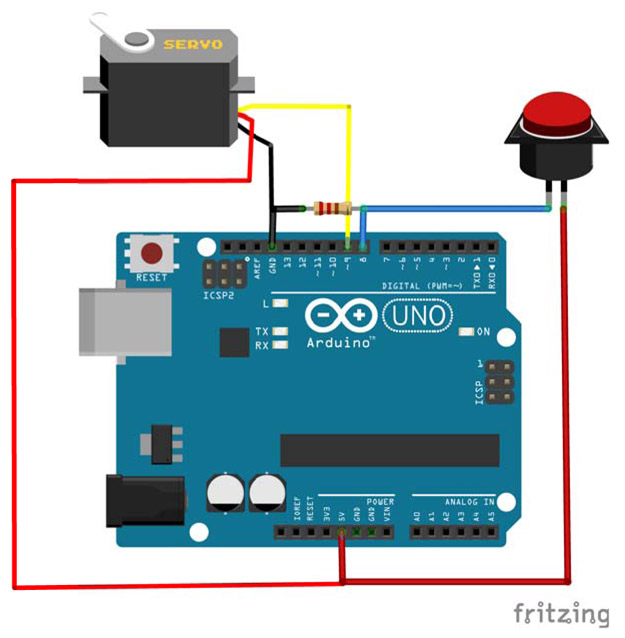
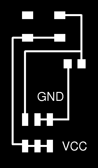
After looking closely at this fritzing diagram below, I realized that I needed a resistor on my circuit and for my signal cable to be on the opposite side of the 10K resistor.
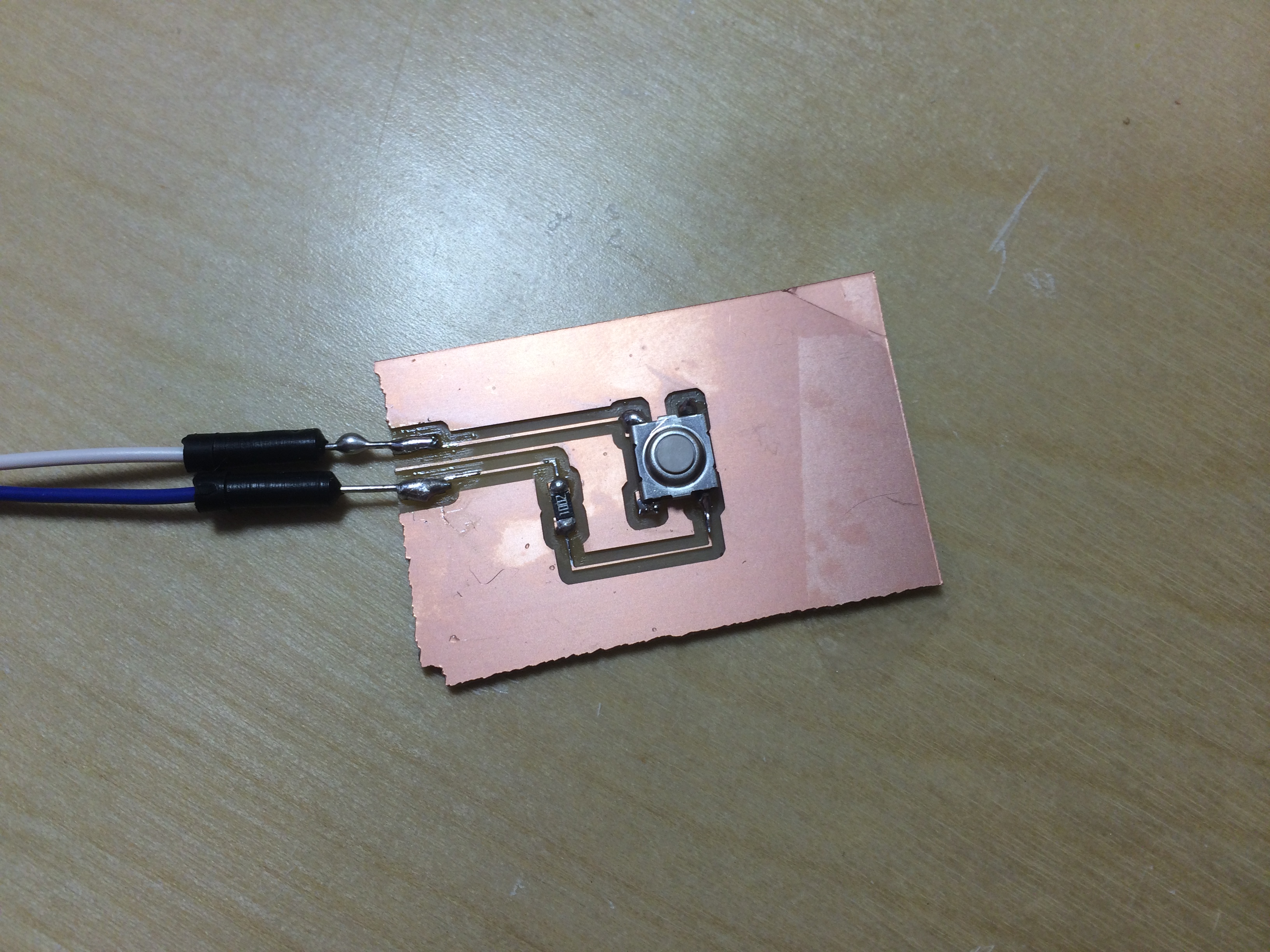
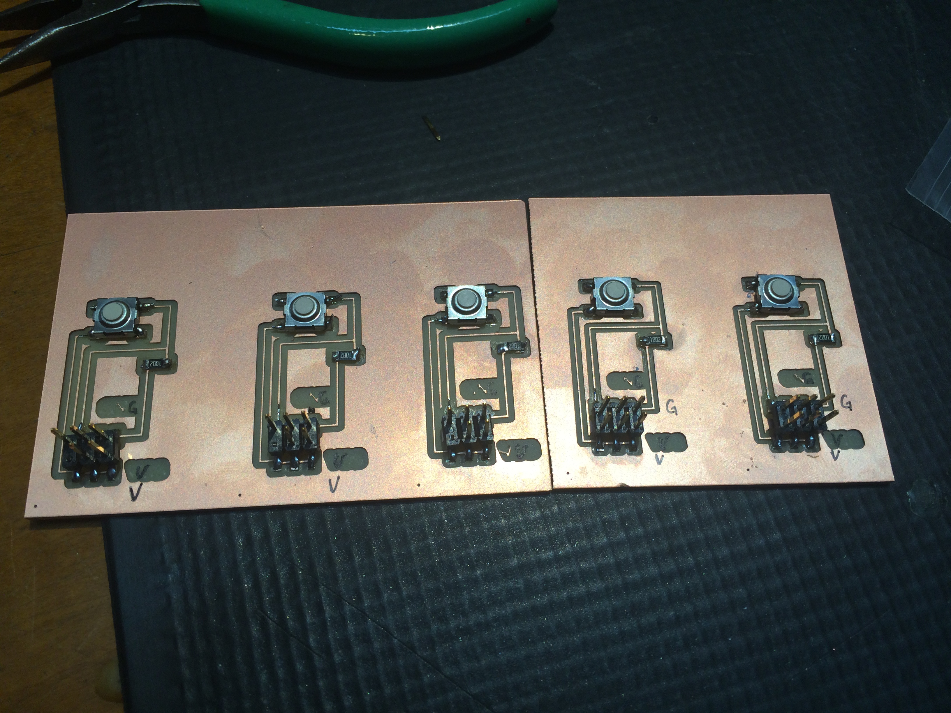
So I did some crazy test soldering on one of my boards that didn't work, and I came up with an ugly, but working control button board.
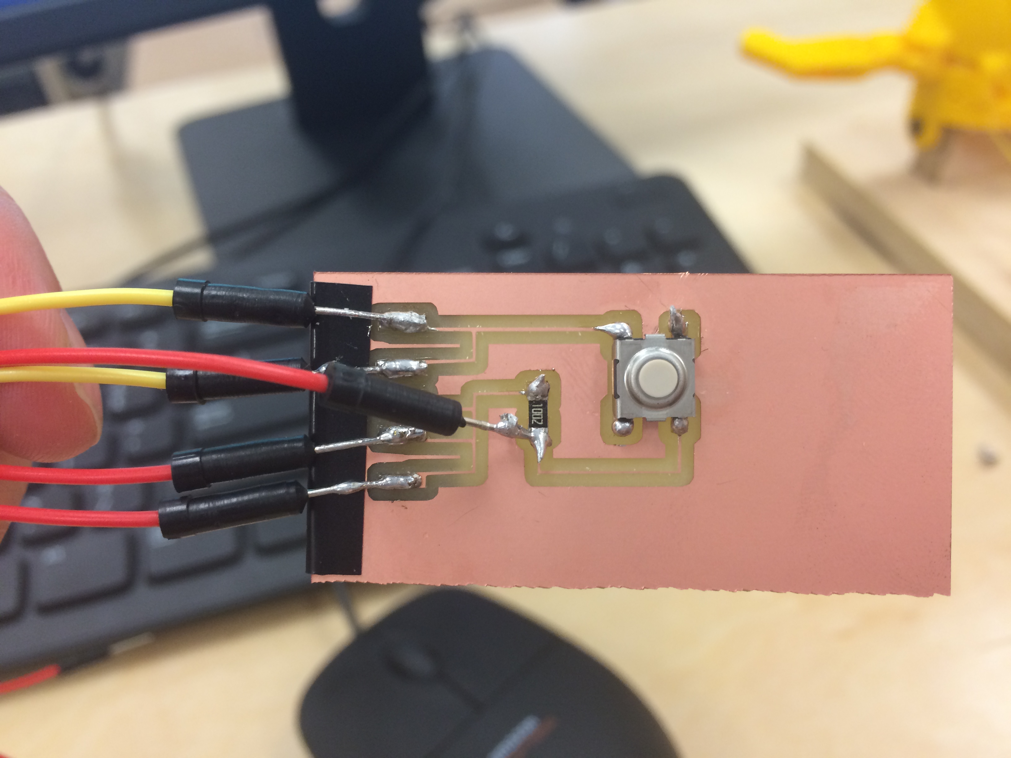
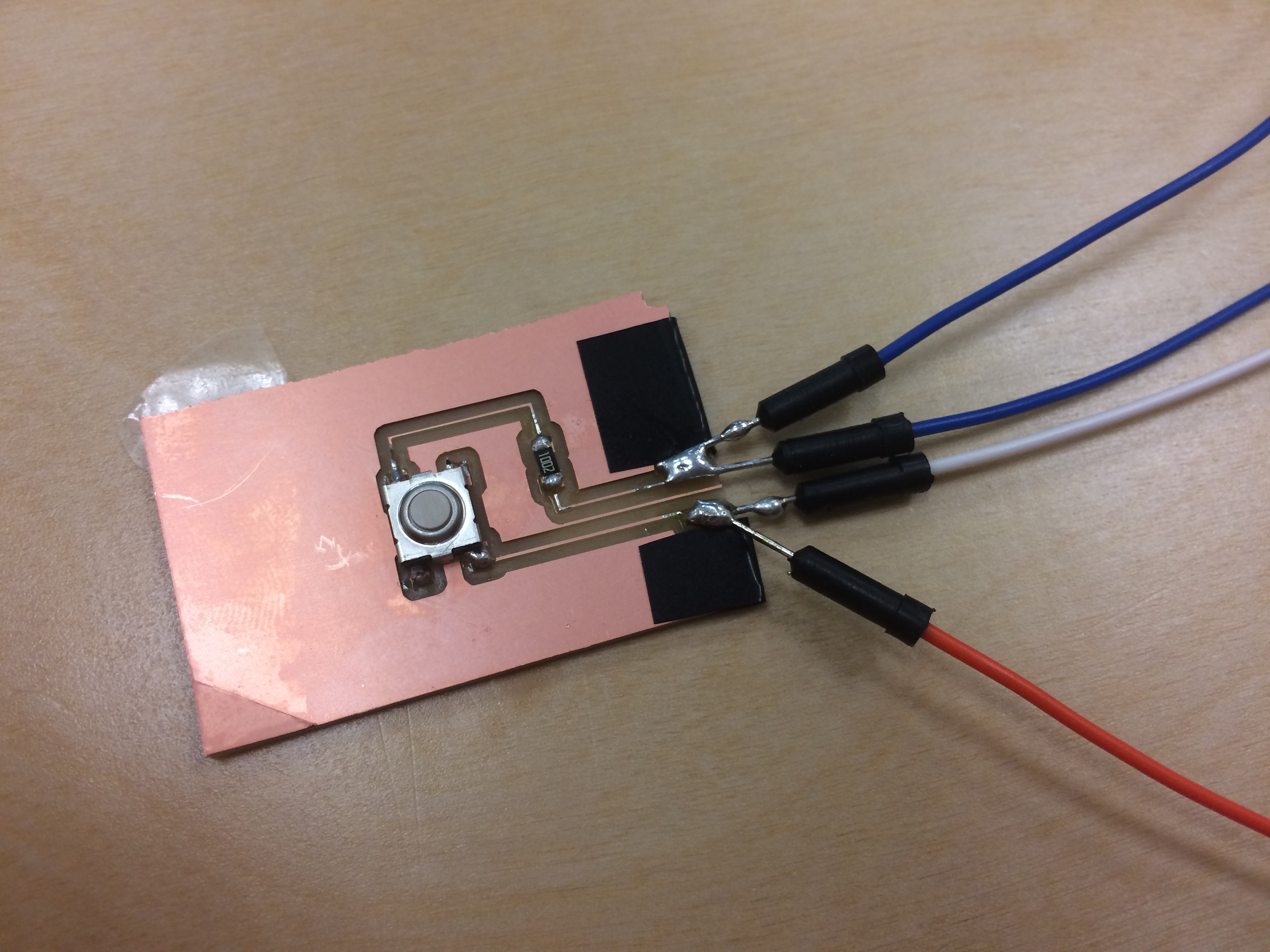
Next, I went into Eagle and I designed a button board with a 6 pin header, 2 GND, 2 VCC, and one control. I cut and stuffed five of them, one for each servo. Here are my eagle files for my button board:
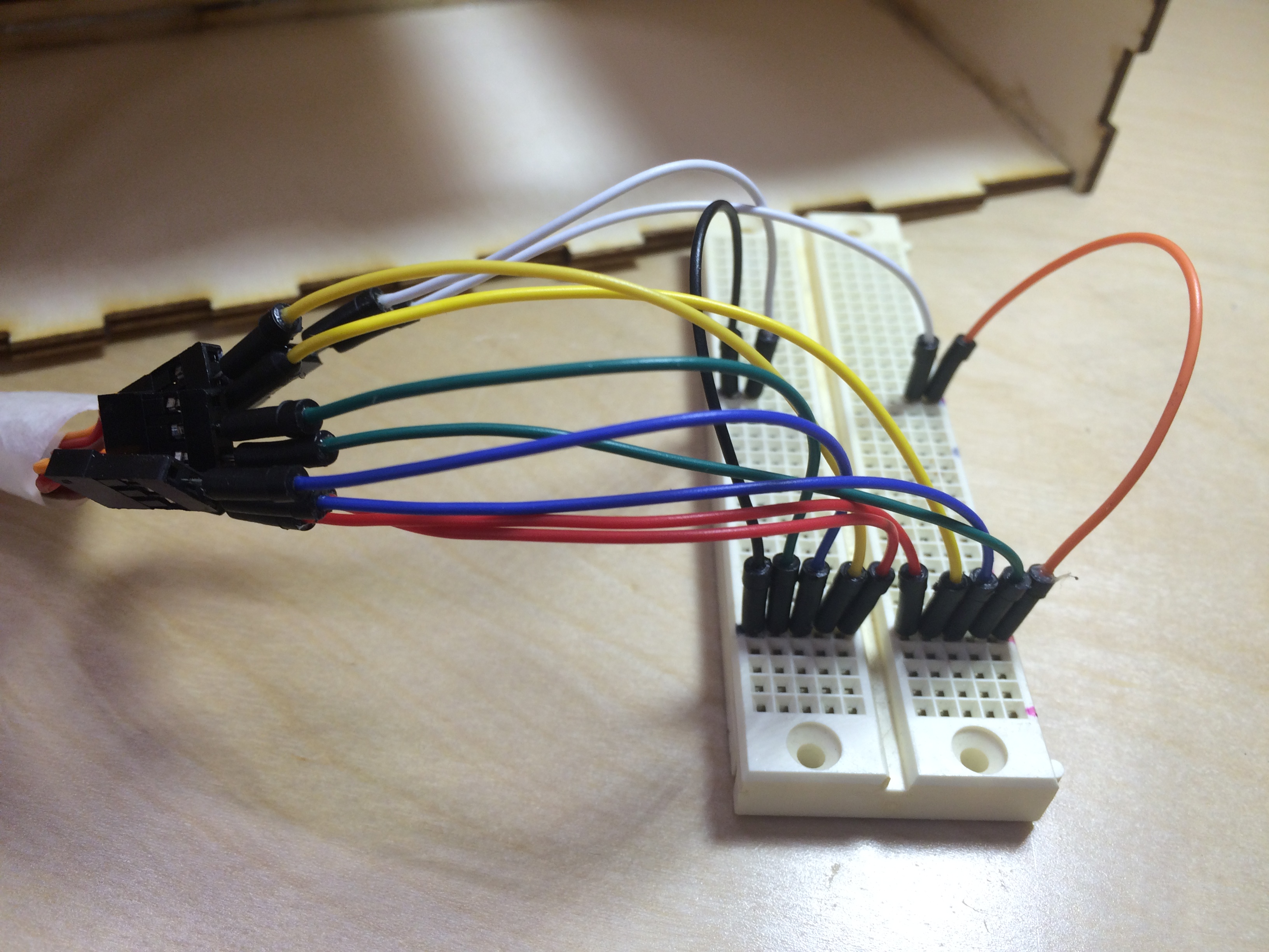
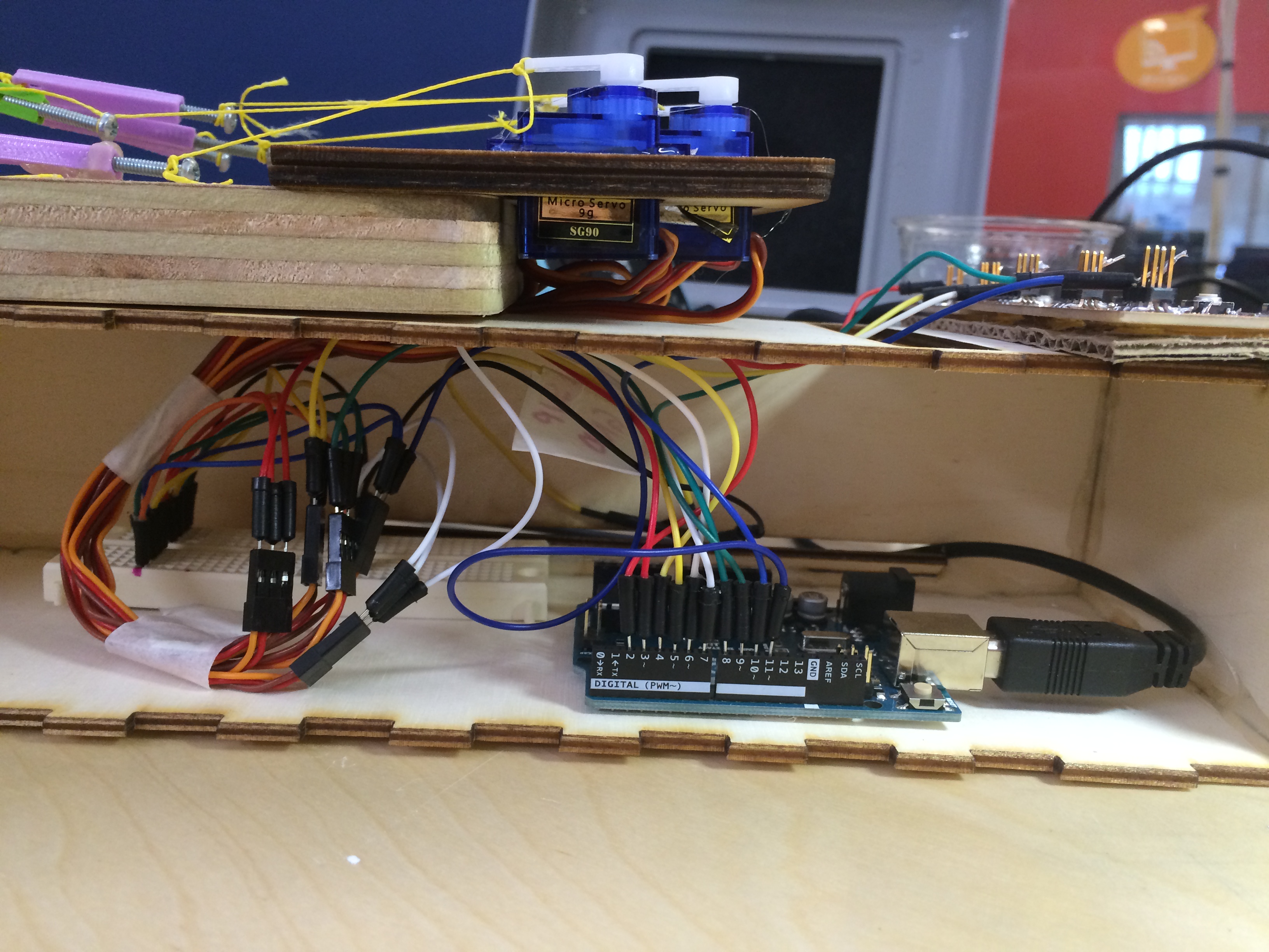
Then I had the challenge of hooking all of this up to the machine, and unfortunately, my wiring got a bit out of hand. I tried to share voltage across all boards to power all 5 servos through the 5V on the arduino. This was a bad idea and it shut down my computer as soon as I plugged it in. Luckily no permanent harm was done, and I learned my lesson about powering servos.
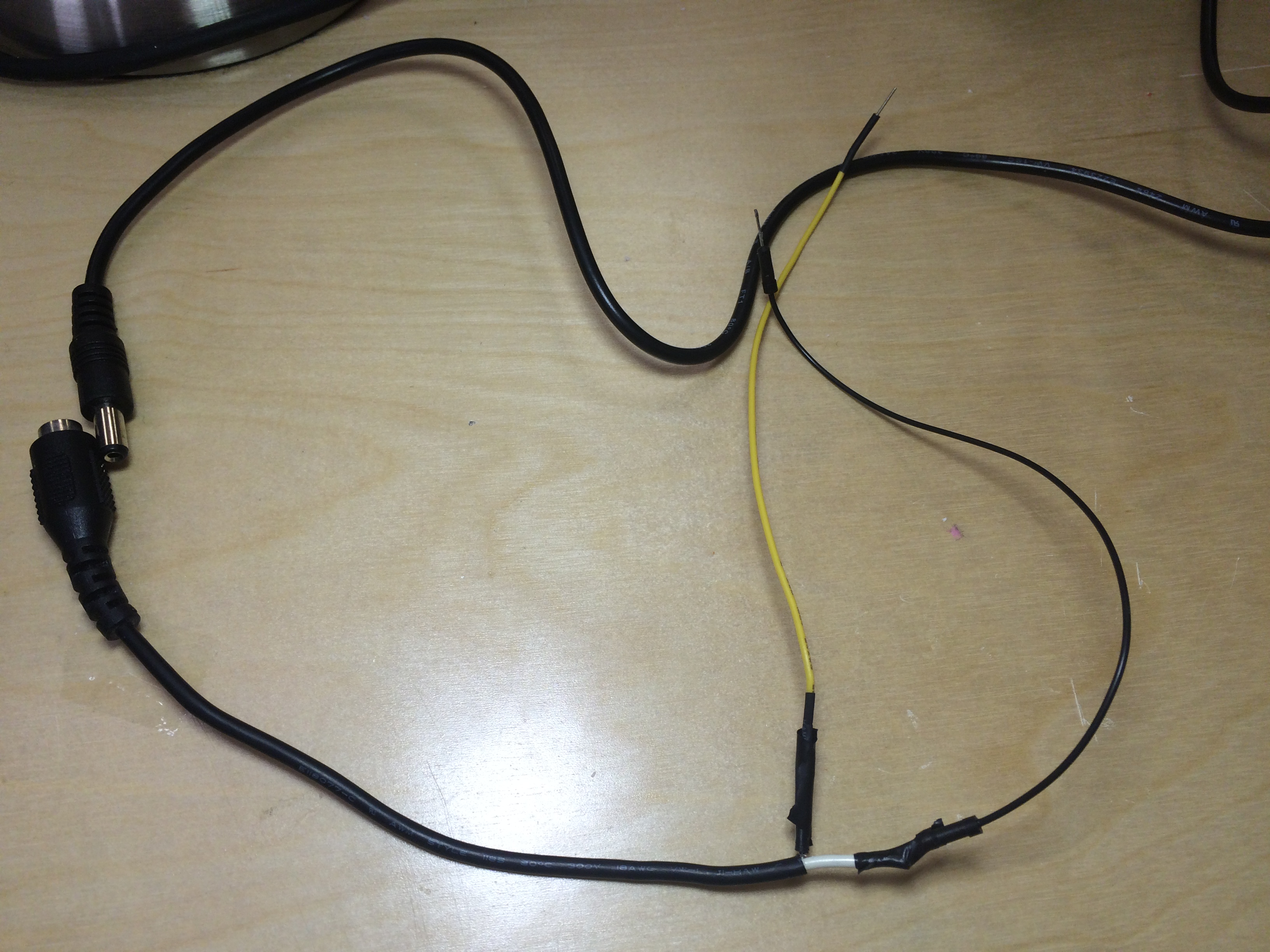
I decided I had to use a separate power supply for my servos, so I adapted a cable (for a 9V plug) and attached it to a power bus. Then I attached all of my servos VCC to the bus, but I crossed the ground with the arduino board. This wiring worked pretty well and we were back in business.
So now the next challenge is programming the board. I started with a simple loop that moved the servo to 90 degrees, waited, and then back to zero with the push of a button. It worked well.
My arduino code can be found here.
Once I had one servo working, I copied the loop I had written and put it in four more times, changing the button number and the servo number. Then I had all 5 servos working to control each finger. The problem was that it only worked for one finger at a time.
So, in order to be able to push one finger down and then another simultaneously, I had to work out a little code. Originally I had this program running under void loop () five times in a row:
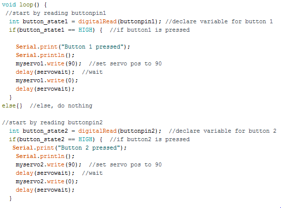
So, what I did was take out the delay and write(0) lines out of each IF statement, and instead I put them down att he bottom of the whole loop. This would allow the computer to read down all the button states, set the servos, and then set them back again at the end of the code.
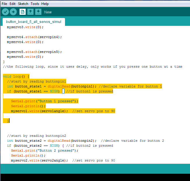
Here is my final arduino code for this demo machine.
In order to hide some of the messy wires, I built a little box to store the electronics in underneath the hand.
Here is a video of all 5 servo motors being conrolled by the individual buttons.