This week was difficult for me as I have NO experience with electronics. Our assignment was to mill and stuff the Fab ISP board. And then to program it!
This was the tutorial I followed to complete the assignment.
My first step was to figure out how to run the Roland mill using Fab Modules. Unfortunately, I couldn't figure out how to use the web-based modules, so I was using the old software. After watching a couple of Youtube videos, I was able to run the machine. I opened up fab modules by typing "fab" into terminal. On the dropdown menus, I selected: input format>image (.png) and output process>Roland MDX-20 mill (.rml) Then, I had this screen
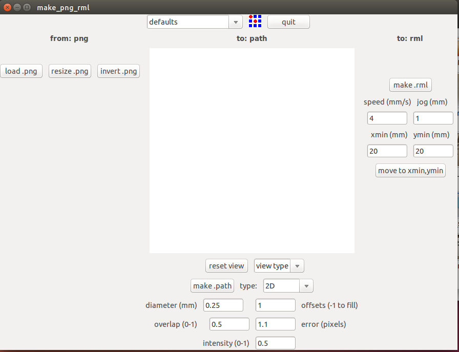
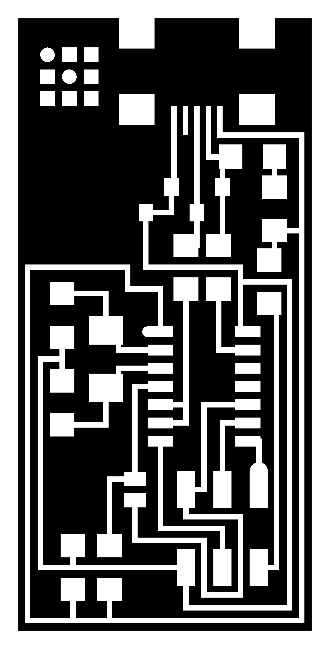
I loaded my PNG file, selected 1/64 traces, and then "make path."
I could control the x and y position of the machine by typing in numbers and then clicking "move to xmin,ymin." You also have to be sure that the machine is NOT in view mode.
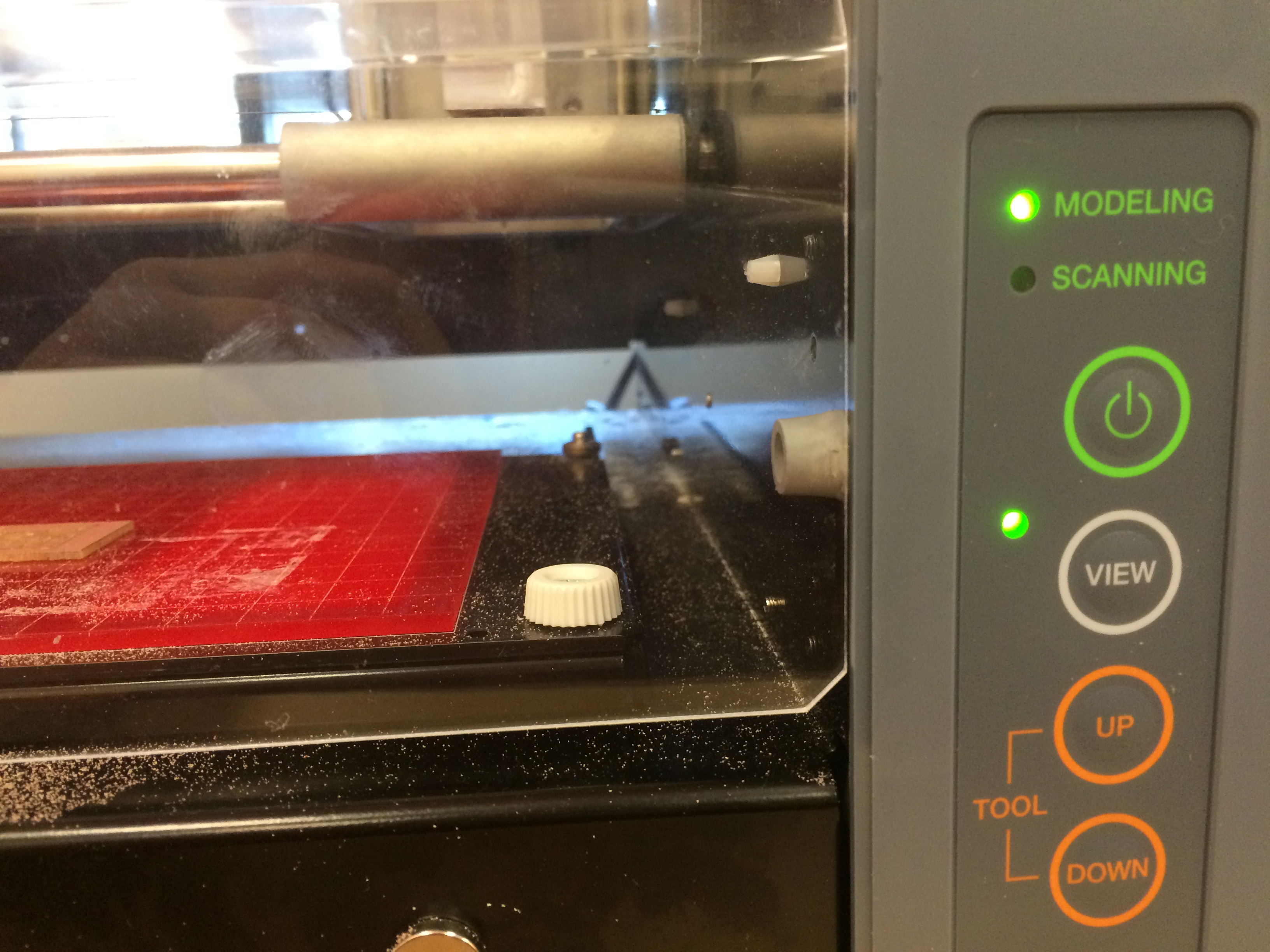
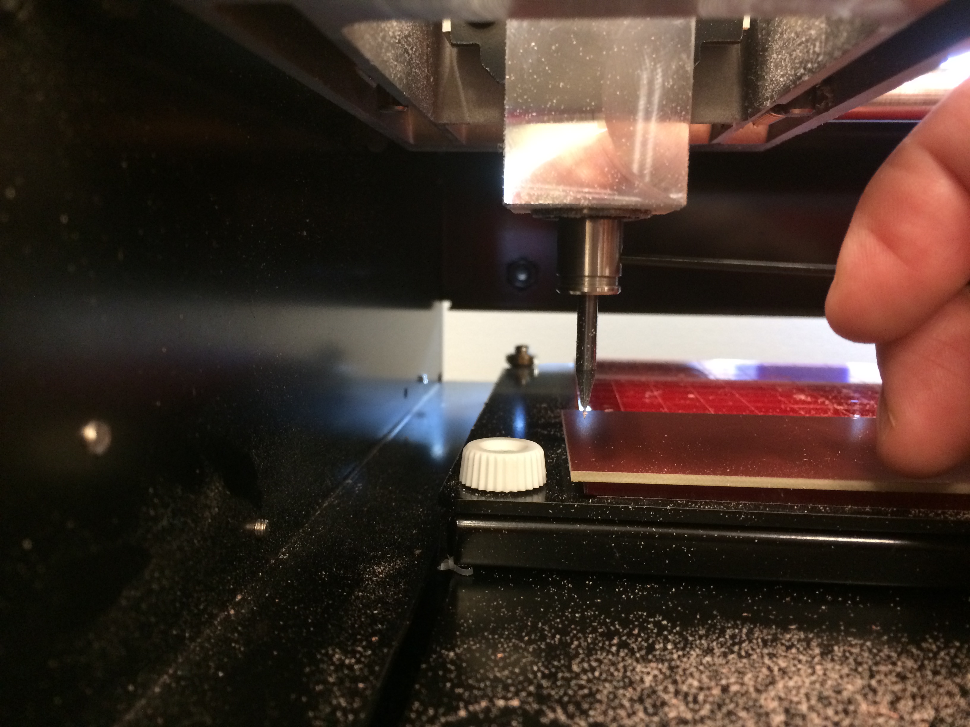
In the above image, the Modela IS in view mode because the green light next to the view button is lit. Also, the tray moves to the lowest point possible on the X and Y while the carriage moves as far away as possible. If your machine is in view mode, you can't control it with the fab modules. Once I got my bit positioned over the lower left corner of the board, I zeroed the Z axis manually. (using the small hex wrench)
Then I hit "make path" again and I was ready to mill my board. (or so I thought)
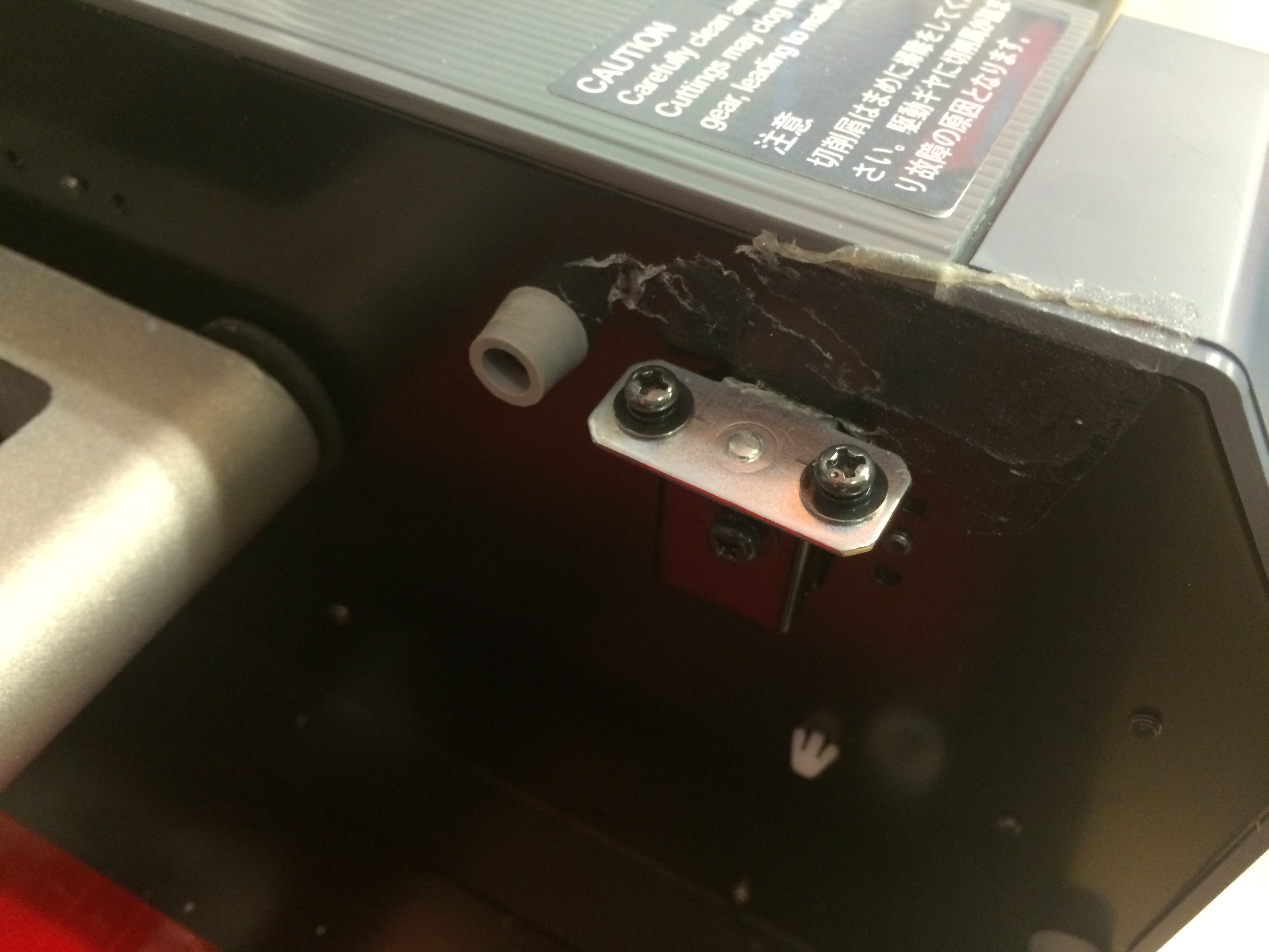
My first mistake was a ridiculous oversight and cost me about 45 minutes of trouble shooting. I didn't have the safety mechanism in place to actually run the machine without the cover off. Once I seated the metal plate back into the switch unit, I could communicate with the machine and I was free to make my next mistake.
My second mistake was also an embarassing oversight, but this one took an hour to figure out! I tried milling my board twice, but it didn't ever seem to cut down into the board deep enough. I messed with the Z setting as much as I could, but it didn't seem to make any difference.
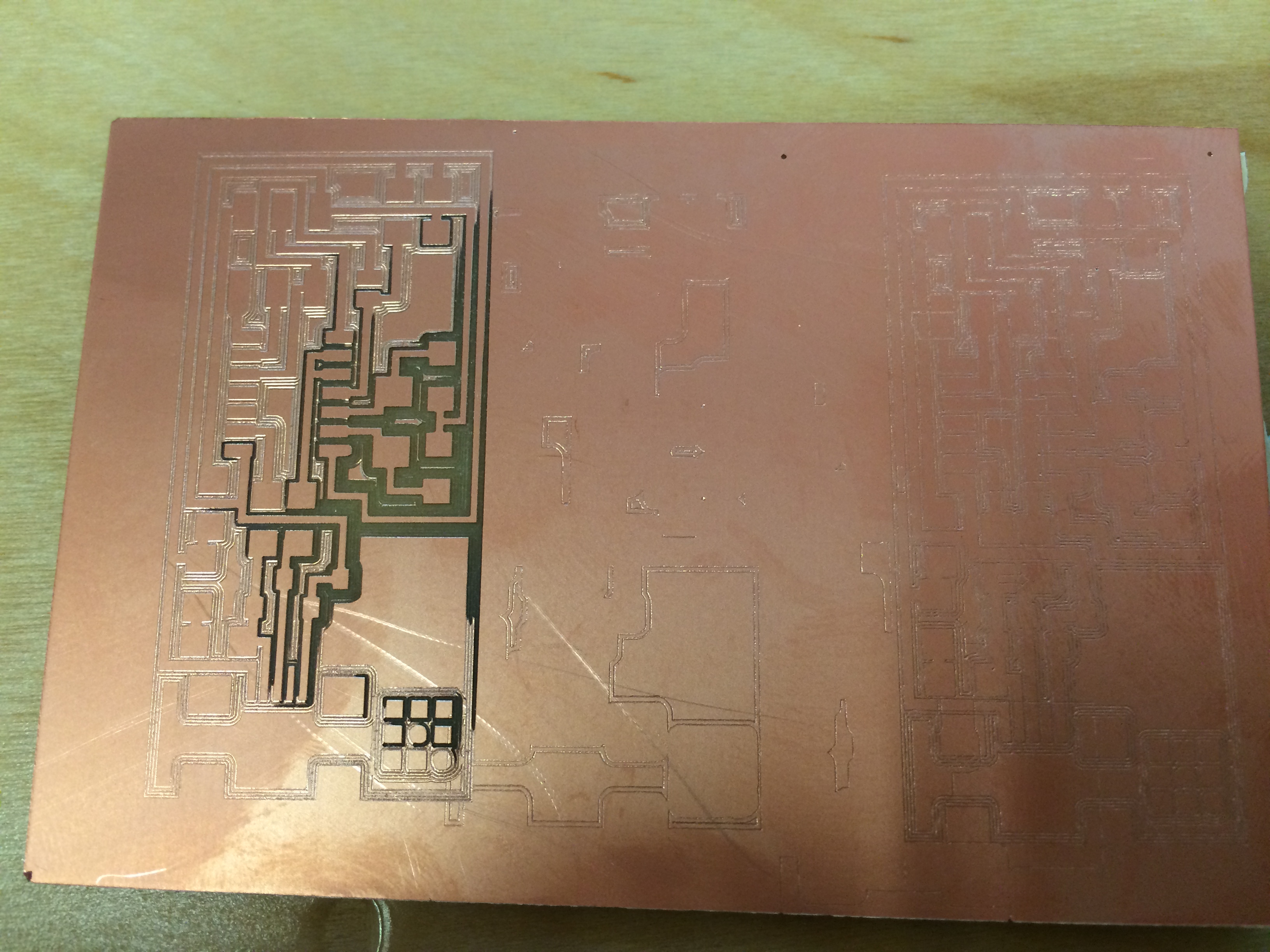
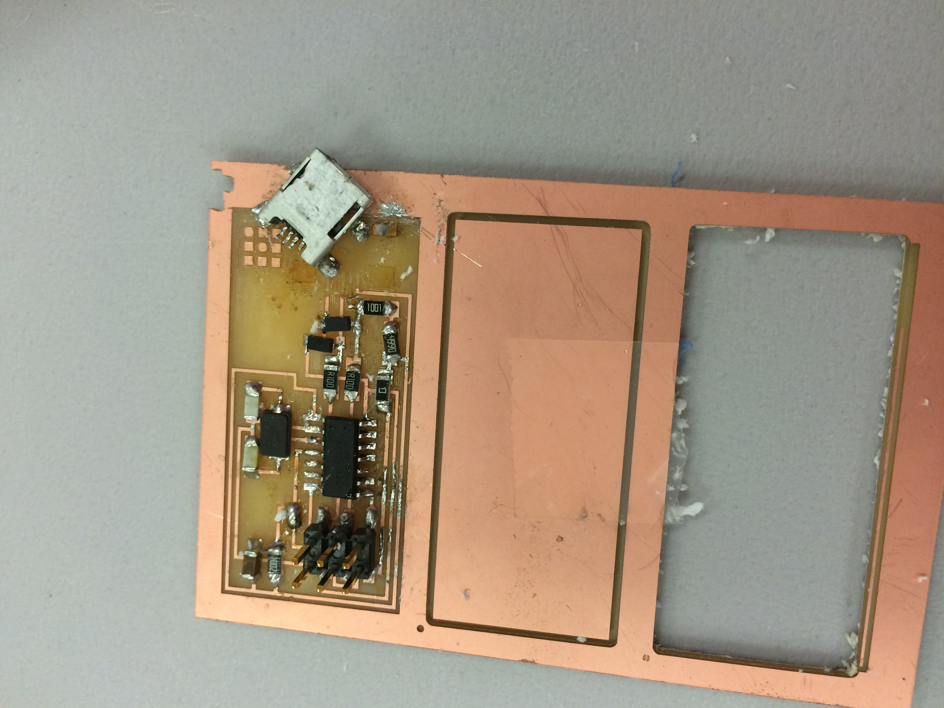
After much head scratching, I eventually decided to change my bit, and the second bit worked great. Here's the thing... it turns out that the first bit I was using was actually a ball nose bit. (I'm trying to blame the staff member who labeled our lab drawers, but still...) Once I switched to an end mill 1/64 bit, it worked great. My first milling project was finally successful!
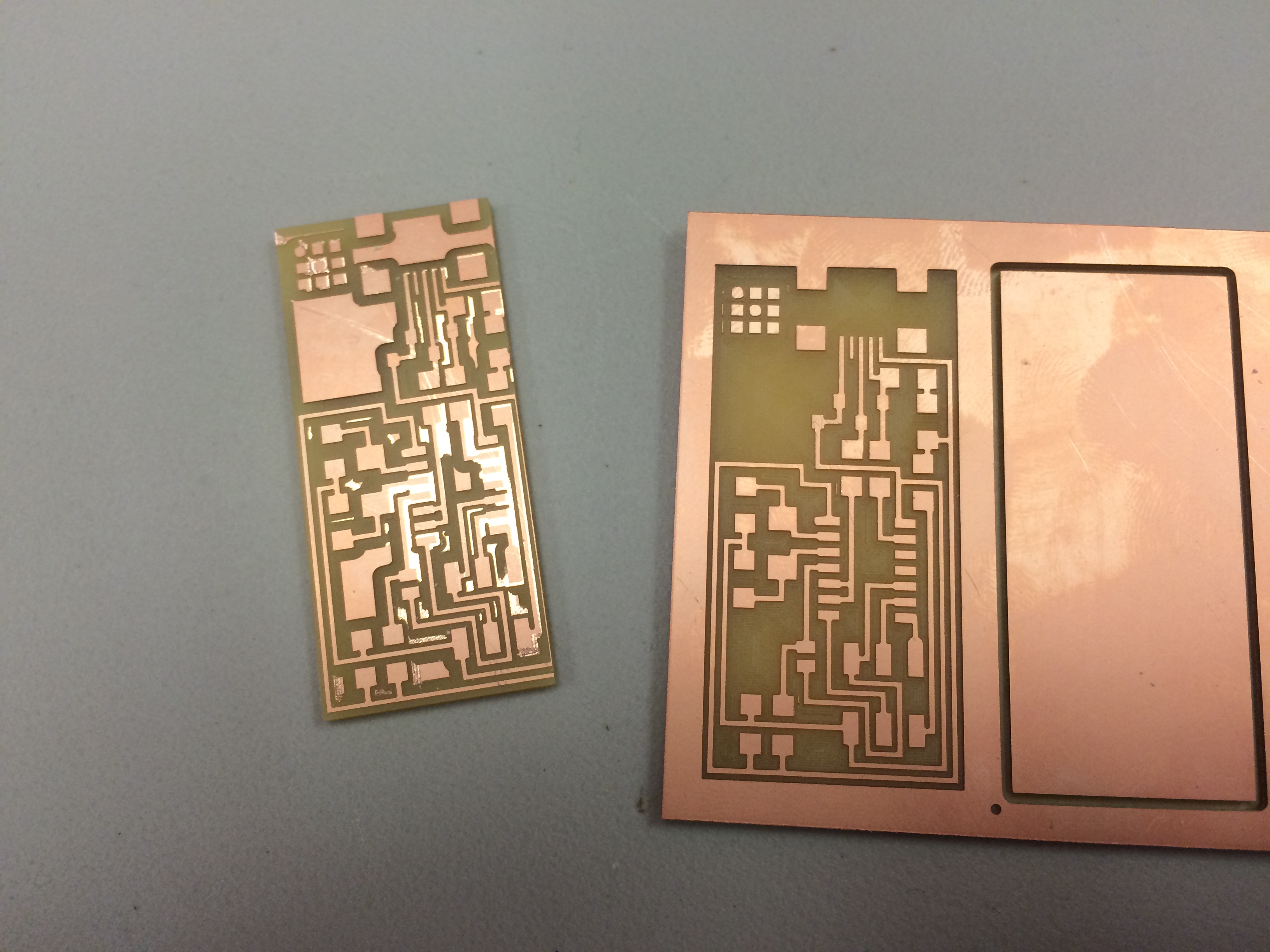
In the above image, the board on the left is the one I milled with a ball nose bit and much hair pulling, the one on the right (not cut out of the board) was milled using the correct bit.
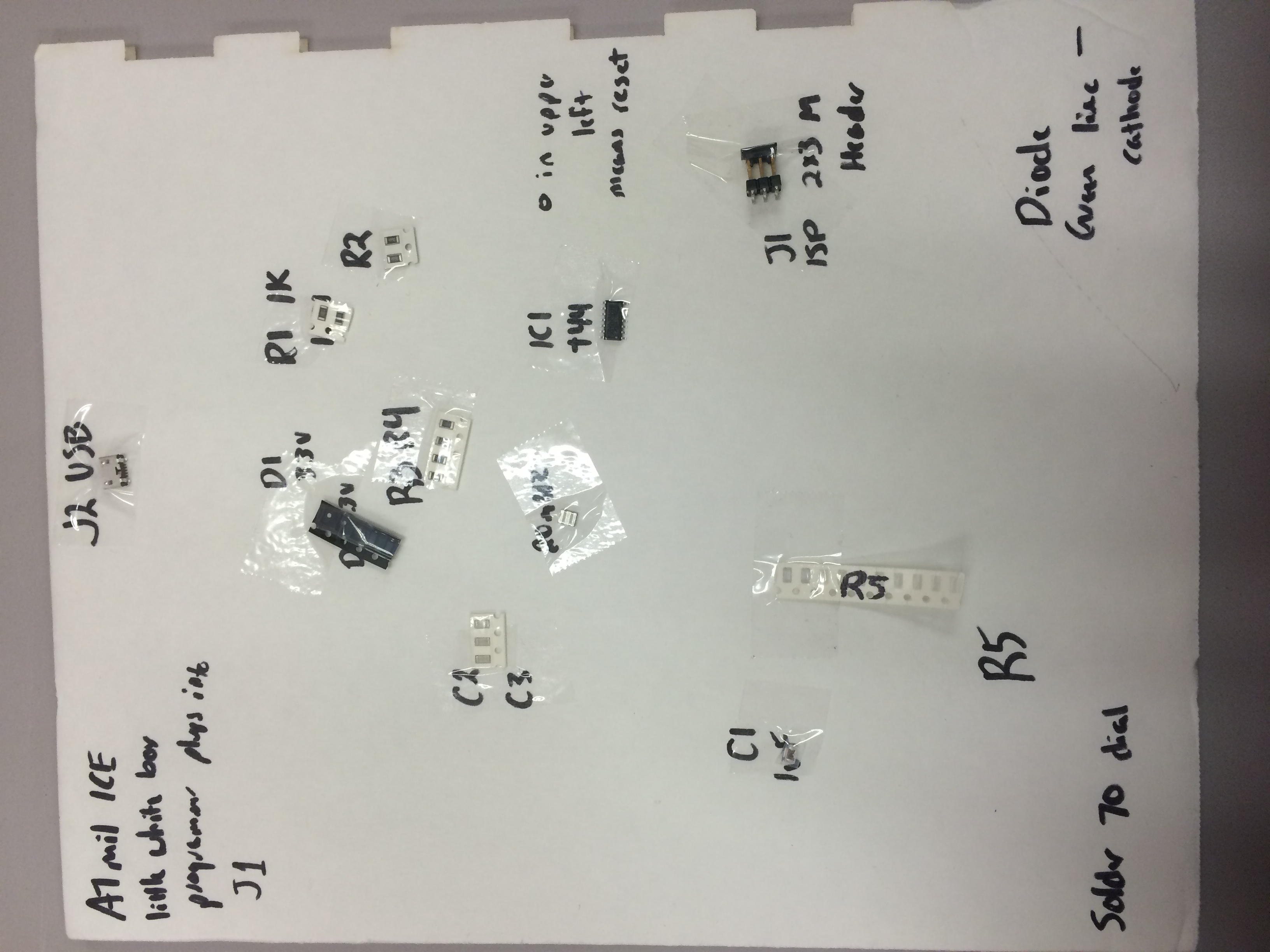
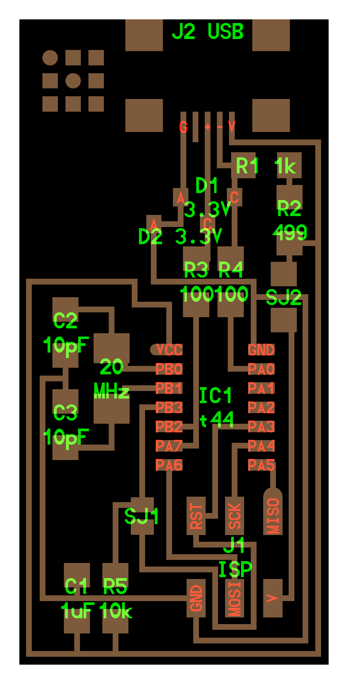
My next challenge was finding all of the parts to solder on my board, and this was difficult. Having no experience with electronics, I was having trouble figuring out what all of the letters meant on the schematic, but, combined with the photo image of the board and help from my guru Kelly through Skype, I was able to piece together the parts. I taped them to a piece of white foam core where I also kept some notes.
So, onto soldering. I am apparently a terrible solderer (if that is an actual word). Soldering on the ATTiny 44 was insufferable. I did improve as the board went on, but it was difficult to clean up the solder that went awry. I eventually figured out how to use the copper solder braid, so I was able to wick away some mis-laid solder, but it wasn't as easy as I thought it would be. Occasionally trying to desolder, I would pull up the copper traces and have to start over again.
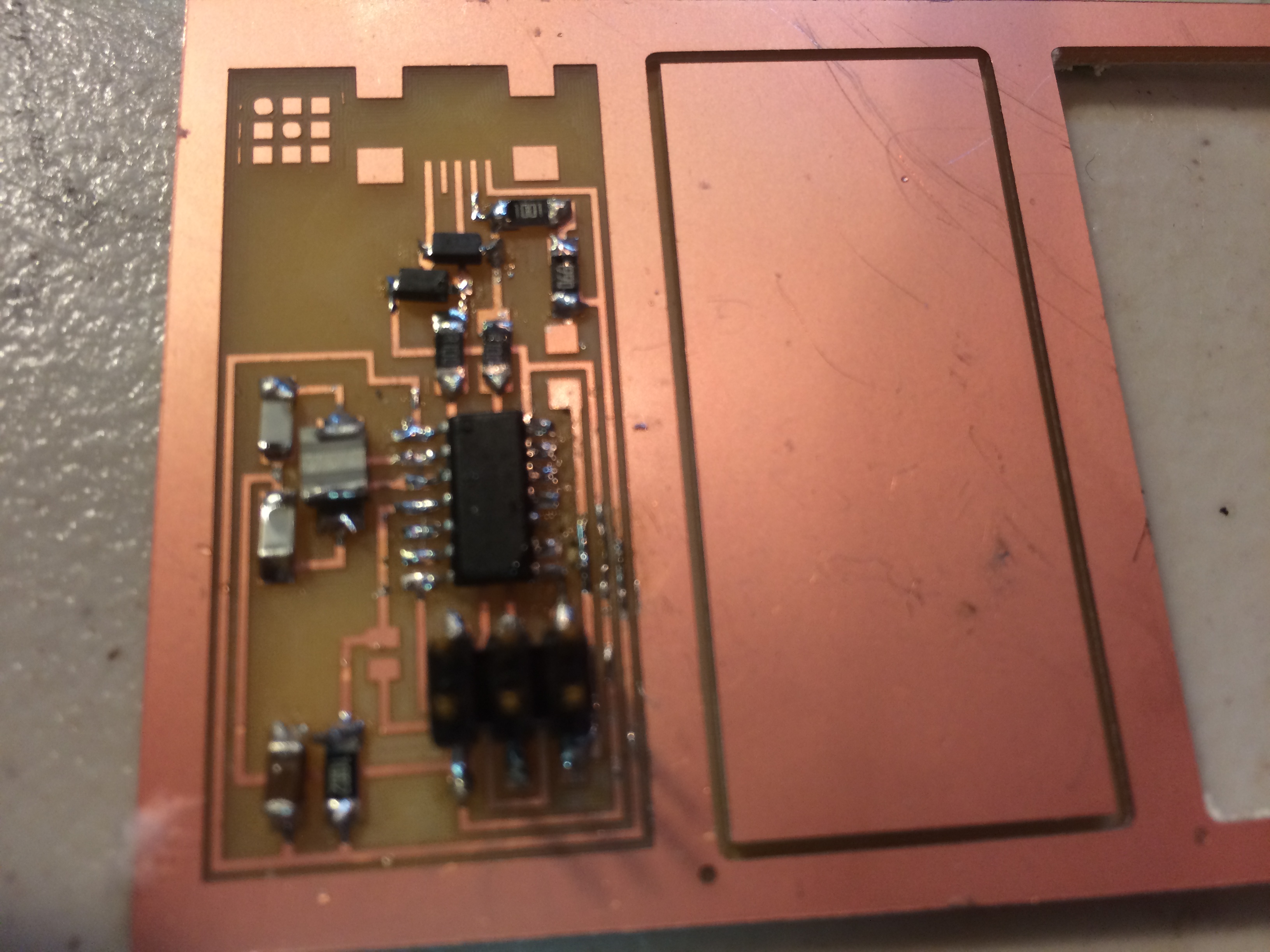
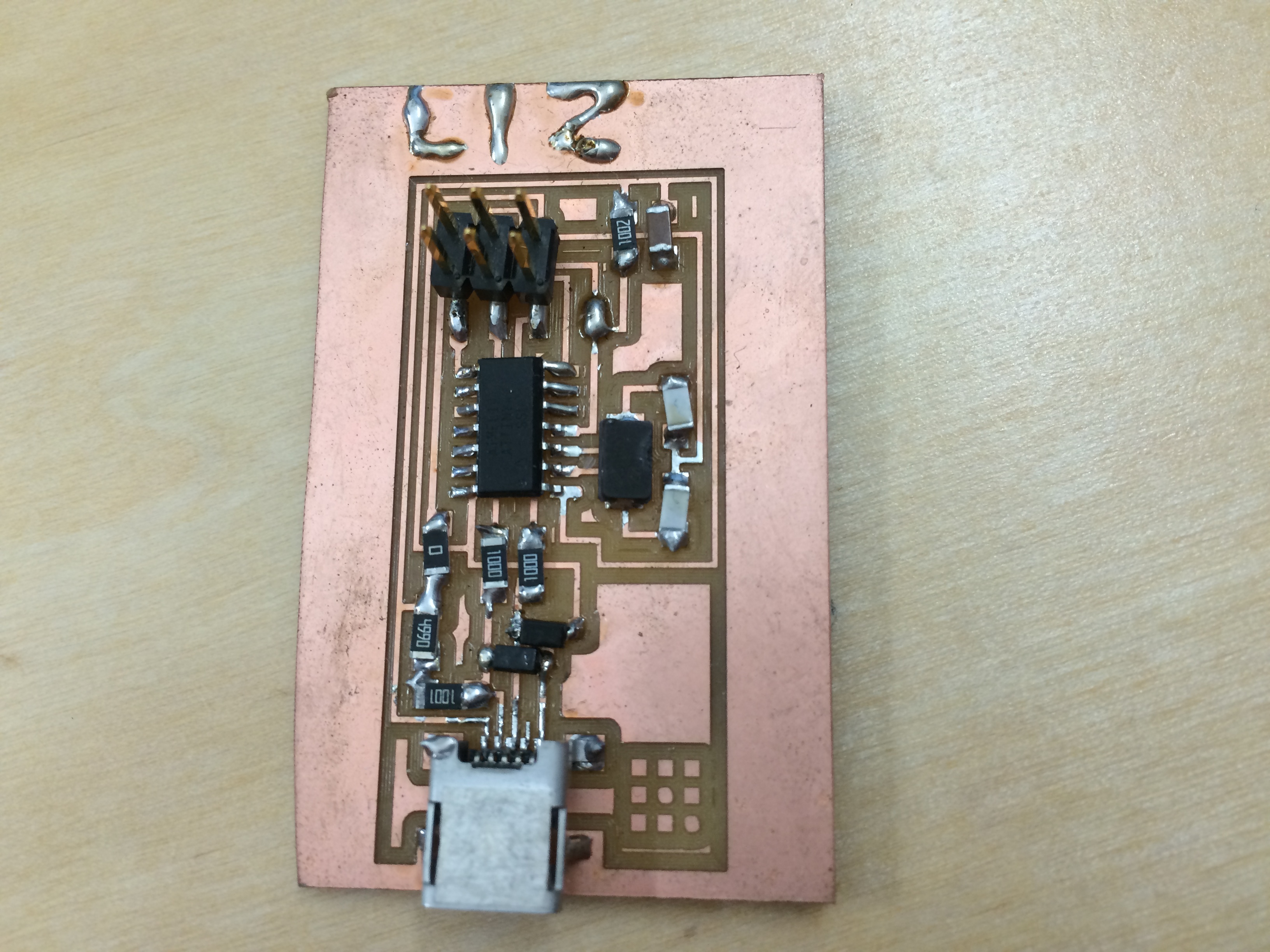
I went through about 4 boards in this fashion: soldering incorrecty and then desoldering incorrectly while pulling up traces. Finally, many hours later, I ended up with my first Fab ISP.
Programming the ISP was difficult. I had a lot of help with this step, thanks to Kelly. I ended up programming this using Terminal on my Ubuntu computer. I had to install avrdude, GCC software, and dependencies. THen I followed these steps to program my fab isp:
With all of the above finished, I just had to "un solder" the two jumpers- one is a 0 ohm resistor and the other just a solder jumper. Luckily, I was getting a lot better at de-soldering, and my board was ready to go as a programmer.