


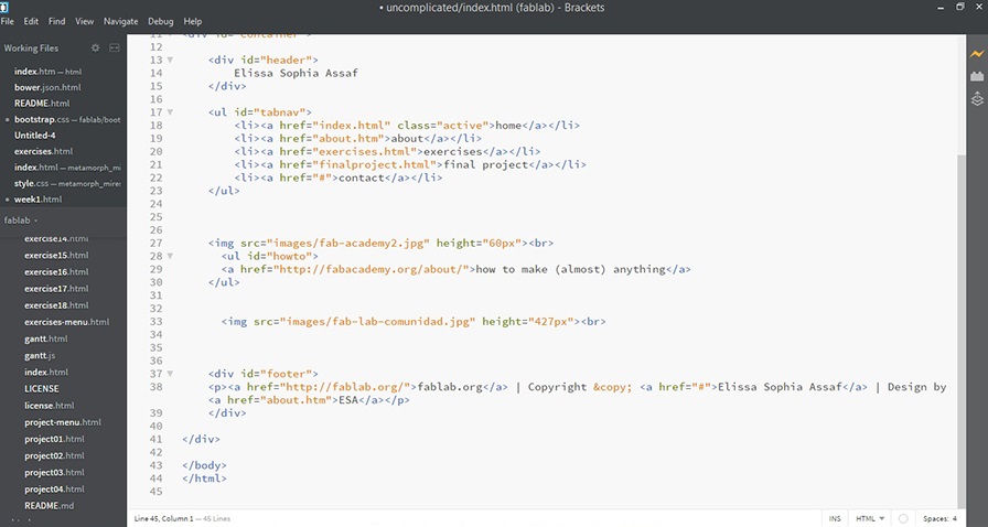
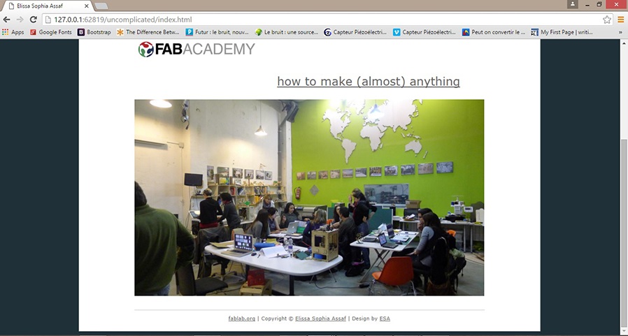
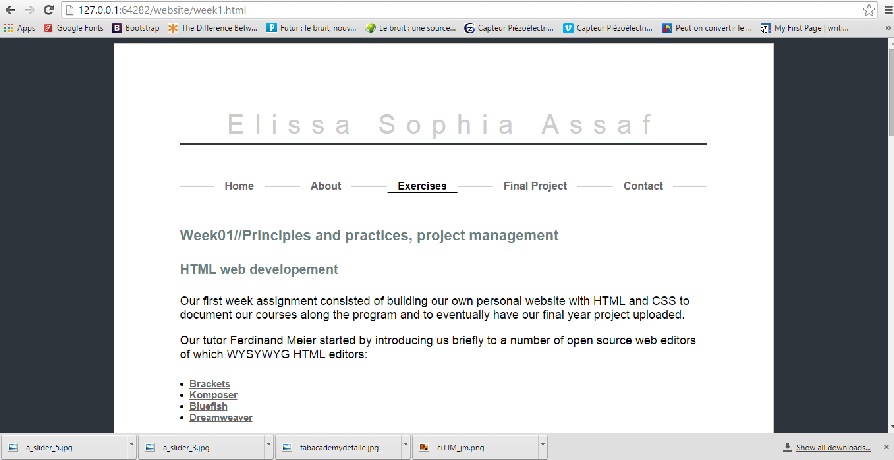
Our first week assignment consisted in building our own personal website with HTML and CSS to document our courses along the program and to eventually have our final year project uploaded.
Our tutor Ferdinand Meier started by introducing us briefly to a number of open source web editors of which WYSYWYG HTML editors:
And some other content management systems CMS HTML:
Seeing as it was my first coding experience, and that the tutorial was mainly about brackets, I decided to use it and picked a relatively simple template on open source web design which I modified as I pleased to make it visually more appealing.
Here are some other open source CSS frameworks for templates:
I also worked on the FabAcademy template, as well as another template I found on metamorphozis which is also open source, but I ended up using one from bootstrap.
As a first-time coder, it will mostly seem like it is a case of error and trial since we've only just learned basic HTML structures, so our tutor recommended we refer to some websites such as W3schools that can be very useful.
Some useful basic HTML tips to keep in mind from the start:
//All images should be compressed to web resolution. 100KB maximum image size.
//Never use special characters, capitals or space in the naming of the HTML files and always organize the different media, css and html files in folders.
To summ it all up, the internal structure of a website would be:
//Html: Create the content of your website; Text, Images etc
//Css : Make the website visually appealing through Fonts, Color, Templates etc.
//Java and (PHP): Make the website smarter and more interactive
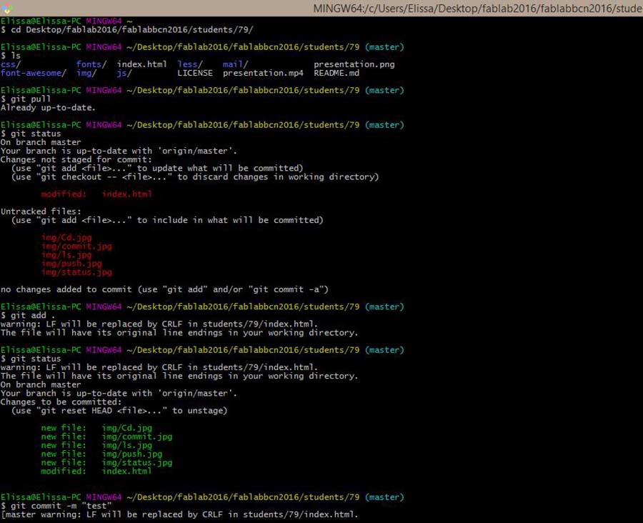
Once the website built, we can start uploading the files from the repository every week through Git.
Git is a free and open source distributed version control system designed to handle everything from small to very large projects with speed and efficiency.
The local repository consists of three "trees" maintained by git. The first one is the Working Directory which holds the actual files. The second one is the Index which acts as a staging area and finally the HEAD which points to the last commit that has been made.
The git commands and steps to follow are the following:
cd to go to the repository file
git pull to upload all the changes made by other students
git add . to add the new files or changes
git commit -m "insert message" to write down the changes made
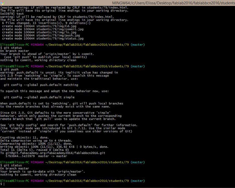
git push to push the changes to the remote server
And last but not least, task and time management are the essential keys to a successful project as Neil Gershenfeld would recommend The Mythical Man-Month as a good read.
Here is the link to our first tutorial.
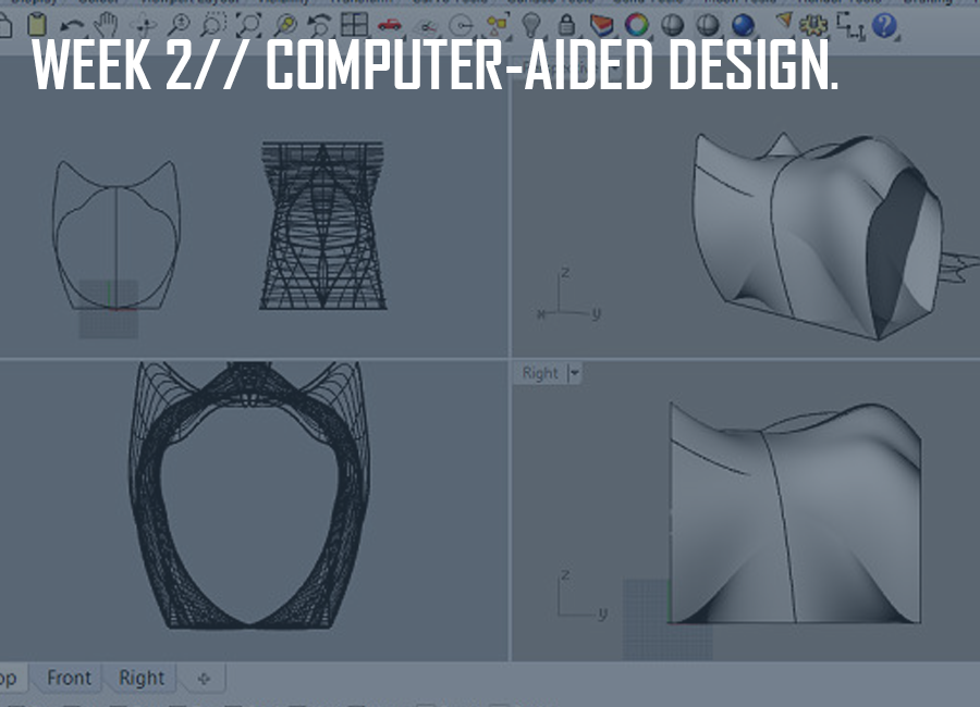
This week's assignment was to draw and model propositions for our final project in 2D and 3D.
We started off the week with going briefly over a list of 2D and 3D softwares, open source as well as commercial, with Neil Gershenfeld.
As starters, to better understand hierarchical, parametric and procedural or algorithmic modeling, read about constructive solid geometry, and parametric modeling.
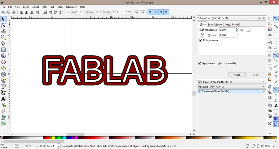
We later had a more detailed introduction to Gimp, an alternative software to Photoshop, and Inkscape, an alternative to Illustrator, with our tutor Ferdinand. We also went over 3D softwares with a general CAD overview.
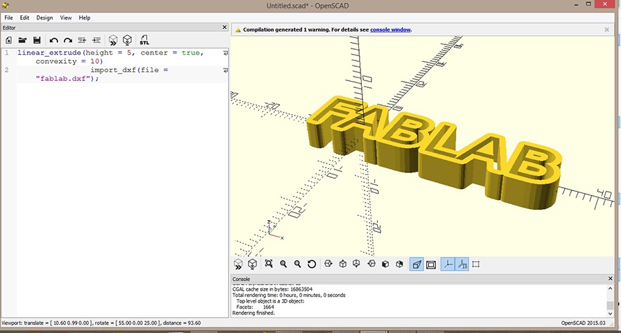
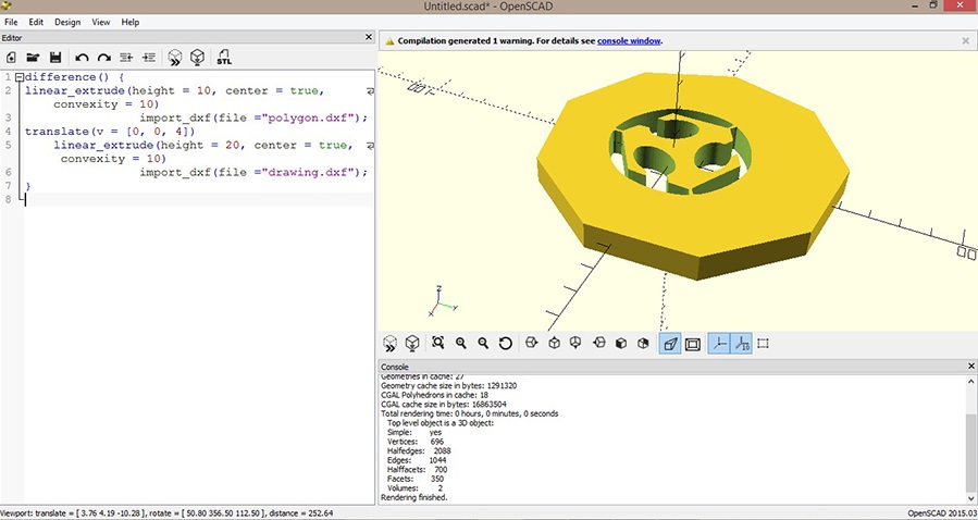
We had a tutorial combining Inkscape with openSCAD as well, which was very informative.
It is important to note a few steps in inkscape before importing to openSCAD: setting the threshold to 0.450, resizing to mm, flattening beziers by going to extensions/modify path, snapping the bitmap to the bottom-left corner and as a final step, saving as "Autocad .dxf" file.
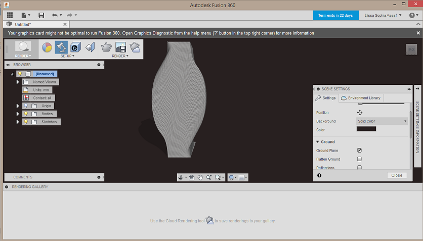
Having a background in interior architecture, I have experience in Autocad (and autocad 3D), SketchUp, 3ds Max (using V-ray to render), as well as in Photoshop and Illustrator. So I decided to venture into other softwares such as Blender which is not a very powerful modeling tool but rather a good one for rendering (simulating and animating the model), and Fusion360, and am looking forward to the SOLIDWORKS tutorial (since FabAcademy has just annouced its partnership with Autodesk and Solidworks that will allow its students and instructors access to software licenses), so I can maybe eventually model the joint part for my modules using the latter program.
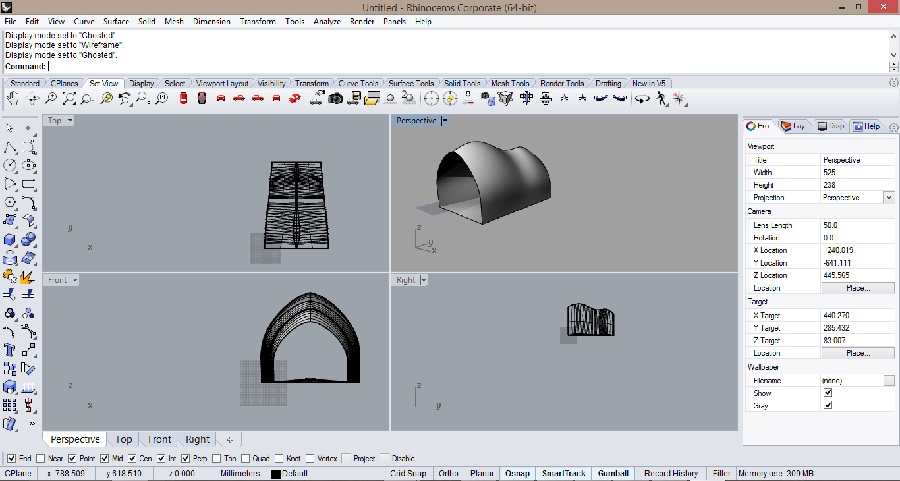
Since I've been wanting to learn Rhinoceros for a while now, I decided to focus more on the modeling of my possible final project on this software. We've also had the chance to have a Rhino tutorial in class, and I had previously downloaded complete step by step tutorials that you can also download here.
Rhino is a NURBS-based 3D modeling software that is not parametric but becomes so when installing Grasshopper which is an extension of rhino. Here is an introduction to rhino/grasshopper.
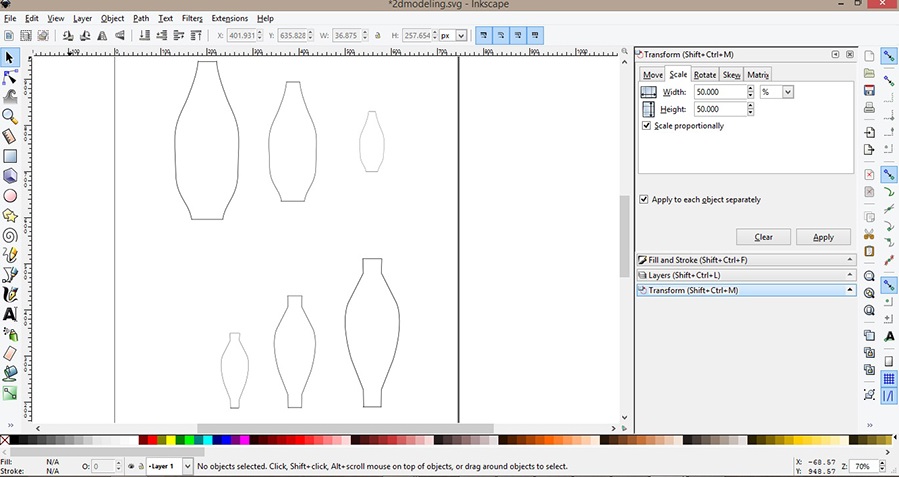
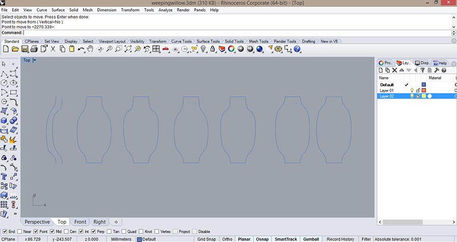
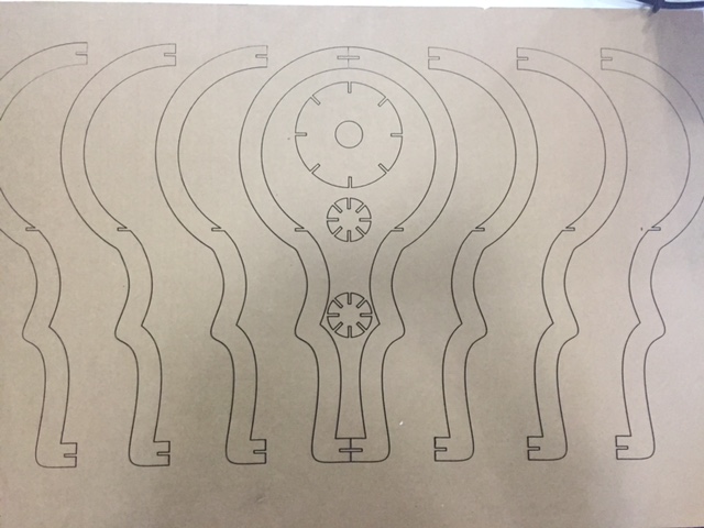
As for my final project, I tried drawing different lineouts for potential shapes in 2D on inkscape at first, using the bezier pen tool.
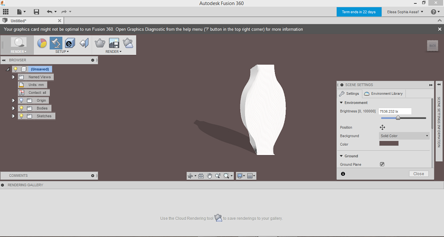
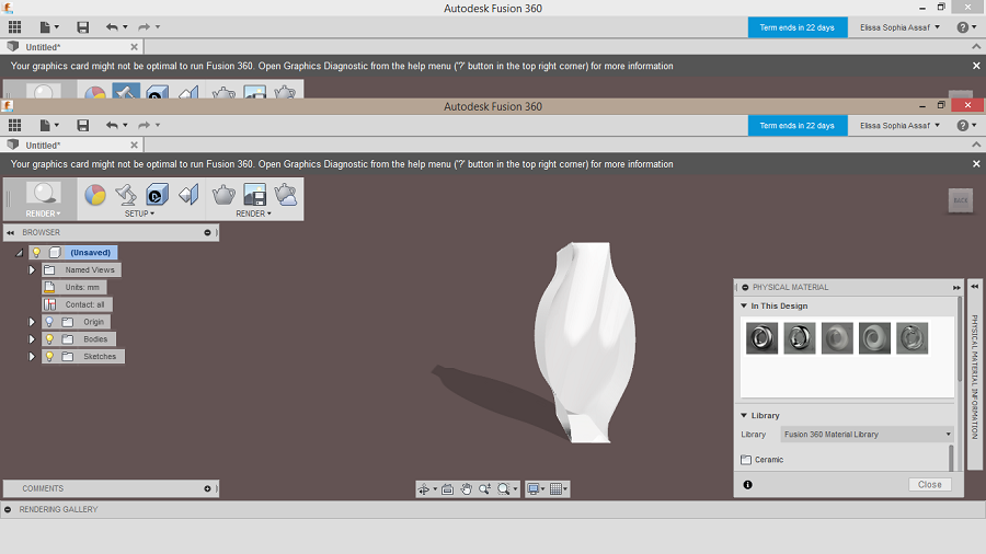
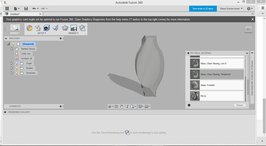
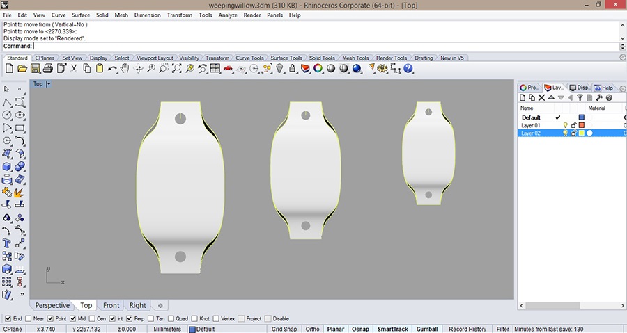
For the 3D drawings, I tried out different shapes (based on fractals) that I wanted to visualize on rhino and ended up with modeling a module in three different sizes that I think I will stick to after a few rectifications in the shape and the way of assembling them.
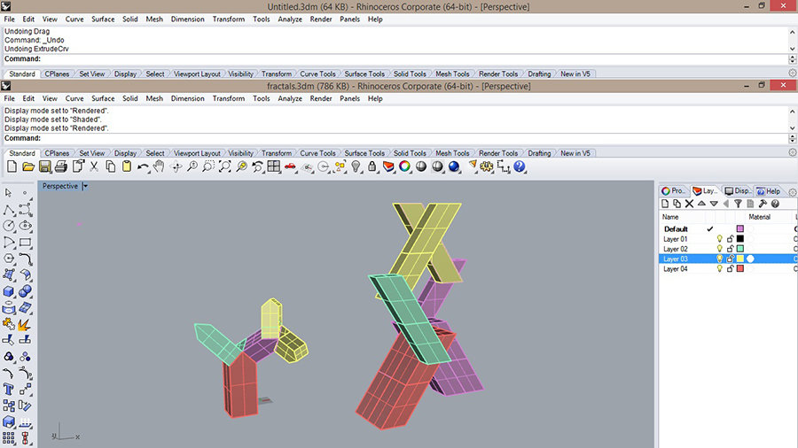
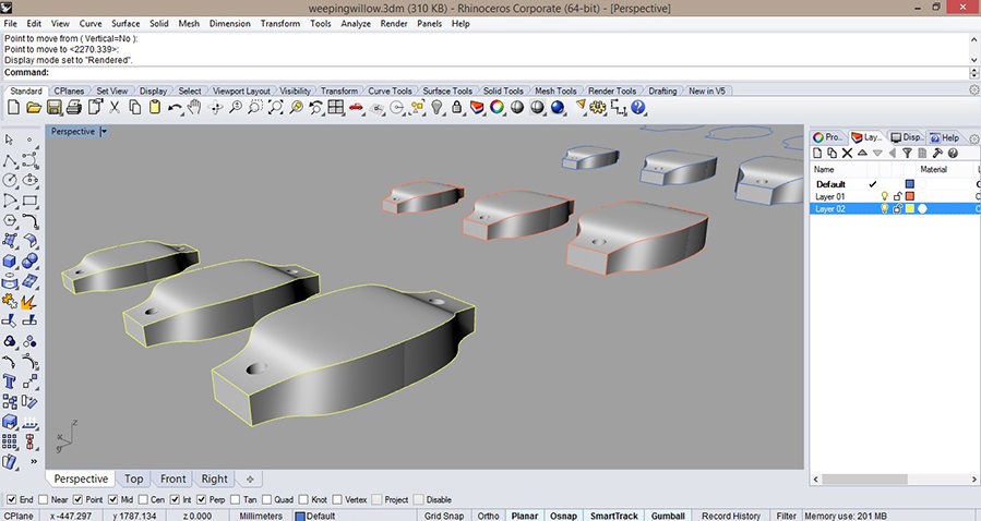
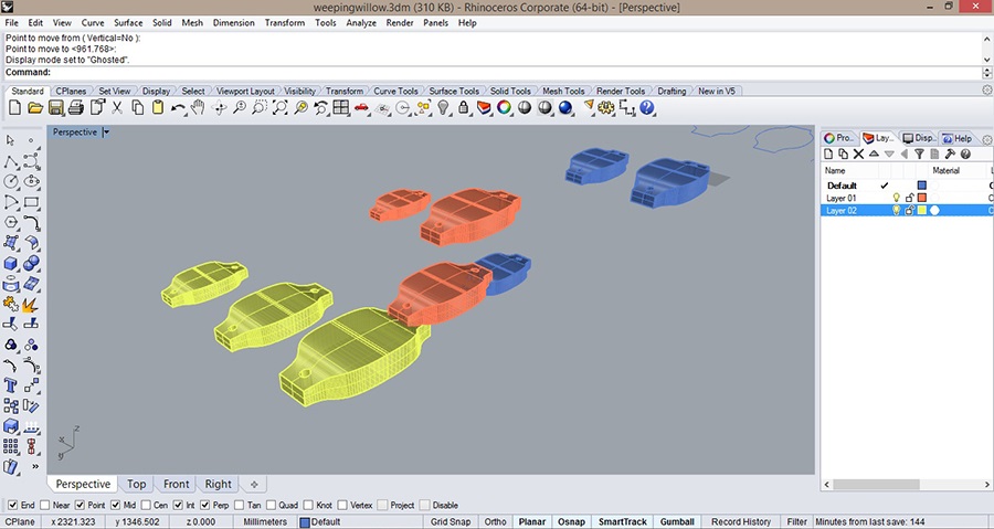
Here's the link to download the file for the modules that show in the image above
I will also try out KeyShot which is a 3D rendering and animation software to render the models and see what different effects they would have with the different colors of light and different combinations.
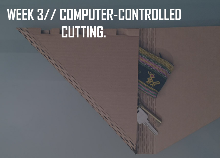
This week's assignment was to design a parametric press fit construction kit (making 3D objects out of 2D cardboard sheets/ representing the joints as parameters) using the laser-cut machines available at the lab.
We first had an introduction to computer-controlled cutting with Neil Gershenfeld, through which we went over the different laser-cut tools and softwares as well as press fit construction kit tips and examples.
A few important things to note are how to set the force and speed to cut and engrave correctly (taking into consideration other components such as the temperature, the humidity and the cleanliness of the blade), and in order to do so, do a small test before cutting the whole file.
Here's a list of configurations that can be helpful reagarding the machines and materials.
The first exercise we did in class was with inkscape to create the 2D laser cut file.
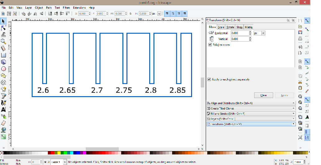
One way of making parametric joints is by using: Clone Object, Align and Distribute, and creating a Boolean (cntrl minus). Changing one joint would then change all of them accordingly.
This exercice was also a way to measure the proper width of the joints according to the thickness of the sheet in order not to make many tests.
There are also plug-ins that can be downloaded to create boxes on inkscape and so to work with parameters.
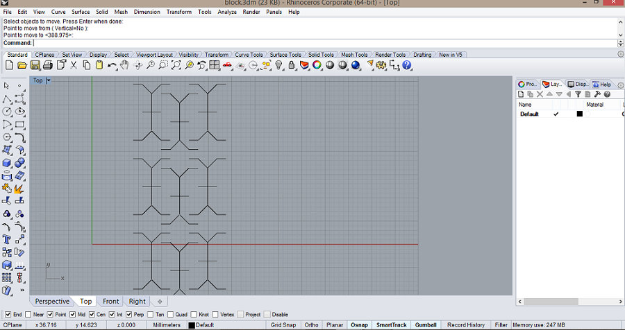
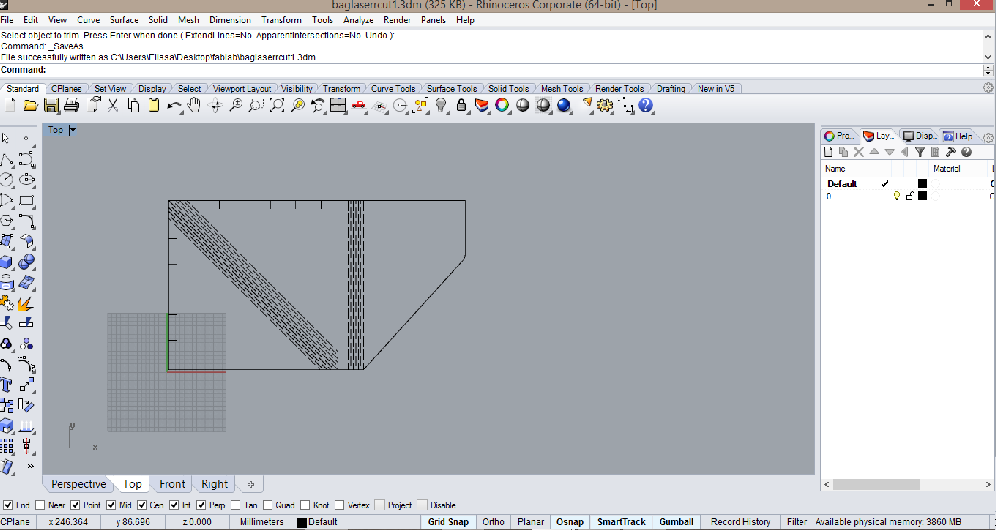
The first press fit construction kit I designed was for a purse using simple joints and kerf bending samples that I made parametric using the method shown in this tutorial.
I then exploded the blocks to erase and trim the extra unwanted lines.
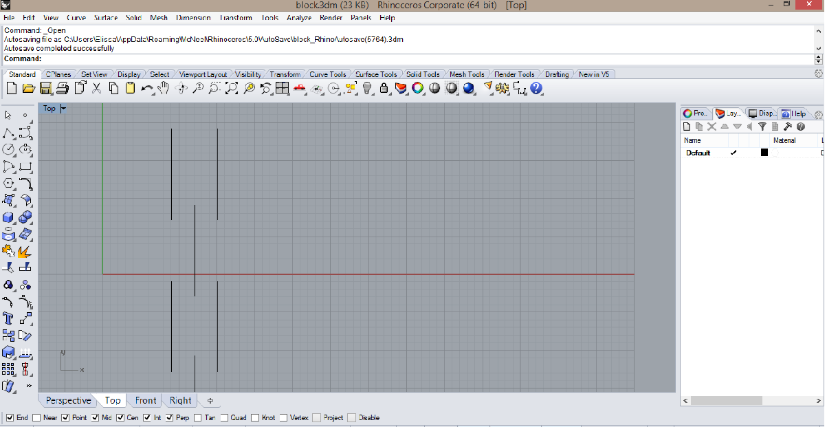
The first step is to draw the joint or the kerf bending pattern and save it as a block.3dm
You then open your 2D drawing file and go to file insert block, as linked and not as embedded.
To edit the parameter, you need to go back to the block file and save the changes made.
You then go back to the 2D drawing file and go to edit/blocks/block properties and refresh.
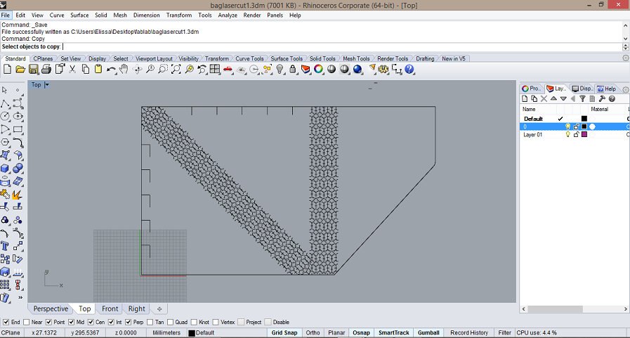
Another way of turning 3D models to 2D sheets on rhino is by using the "unroll" command.
Once I had the 2D files ready, I first used the bigger machine, multicam 2000 laser, with speed set to 20 and power to 60, and then the smaller one, epilog, with speed set to 19 and power set to 100.
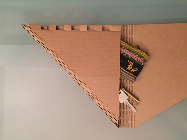
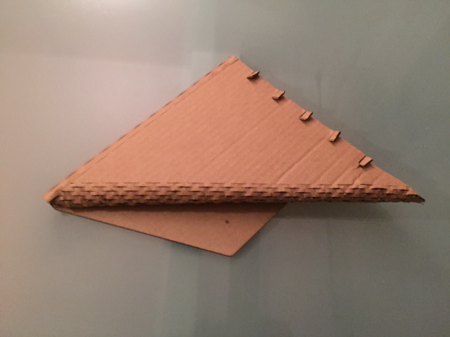
Here's the link to download the laser-cut file for the purse.
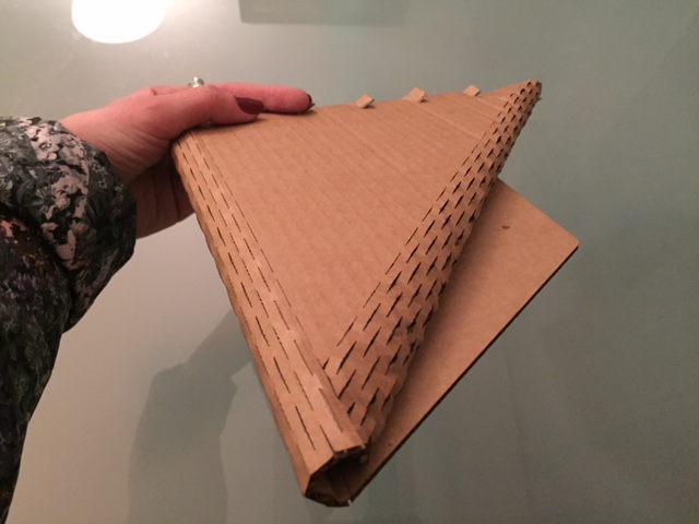
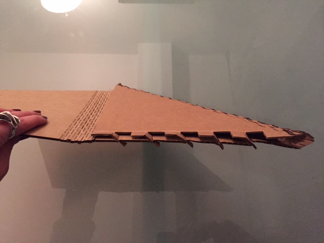
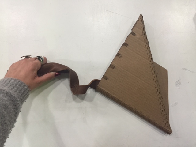
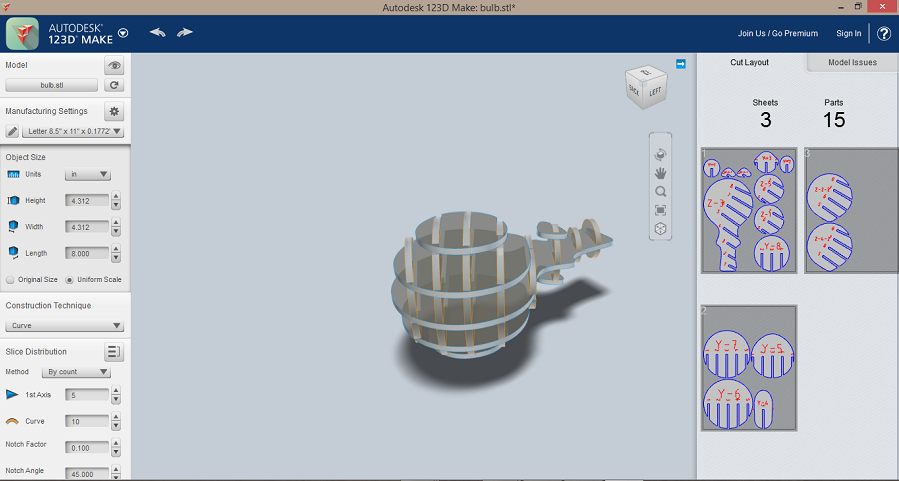
A second press fit construction kit I made is one to cover a light bulb to use either as a table lamp or a pendant lamp since I needed one anyway. I set the speed to 15 and the power to 100 this time but since a lot of people had used it right before me the lense wasn't clean enough so there were parts (mainly in the middle where the cardboard is a little bit bent) where the laser hadn't cut through.
This is another example of press fit construction kit where you can use simple parametric shapes that you can edit on rhino.
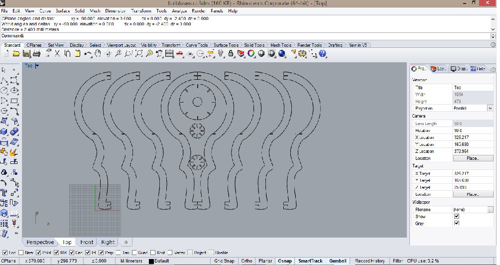
You can download the file for the light bulb here
Another example of press fit construction kit is the box I made for the Mechanical Design week with more details on the trials and errors using the Multicam 2000 with different materials and parameters.
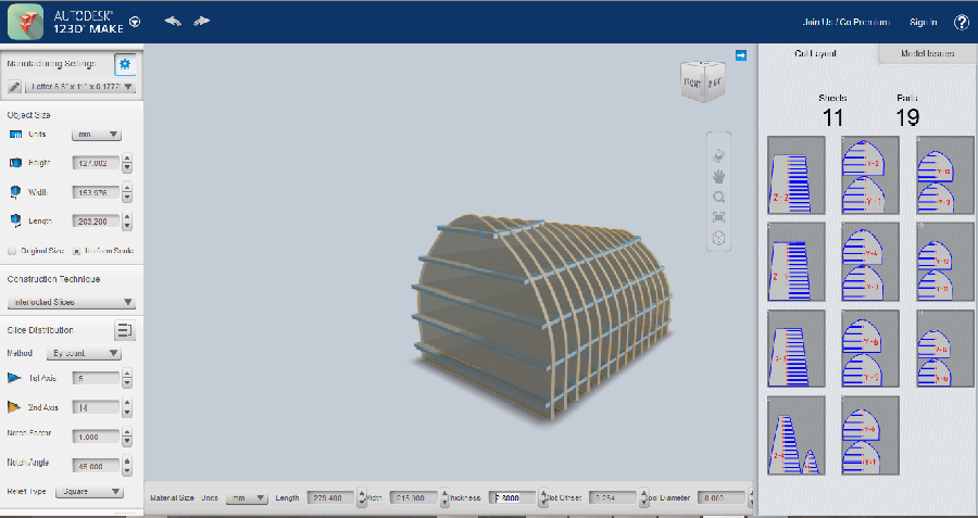
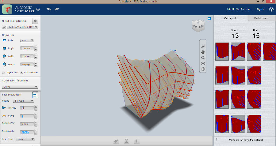
I had a little adventure using 123Dmake which is a fun tool that helps decompose 3D shapes to 2D parts that you can reassemble after laser-cutting. After I had imported the different designs I had modeled on rhino as cribs for kittens I could eventually modify the 2D pieces to get them laser-cut but they require thicker material than 3mm cardboard so I ended up laser-cutting the kits that I found to be of good use only.
There are different construction techniques for a model. It can be made by stacked slice, interlocked slices, curved, radial slices, folded panels, or 3D slices.

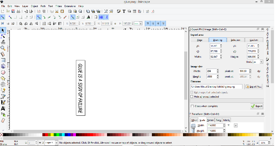
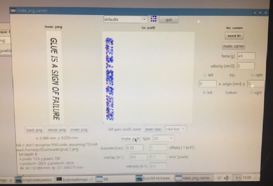
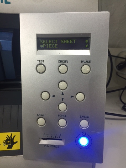
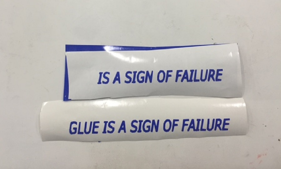
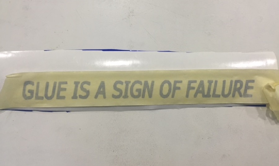
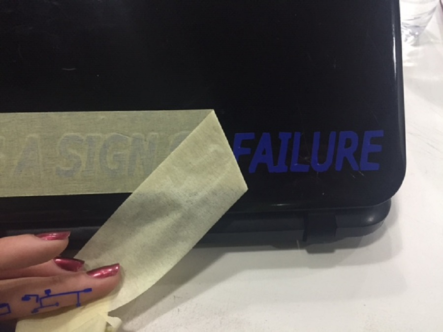
I also tested the Roland vinyl cutter machine, using a file I created on inkscape.
Since I had used typography on inkscape, I was working on vectors, but the mistake I had made was saving the file as a .png instead of a .svg which is vector format, so the result was that the curves of the letters were not smooth.
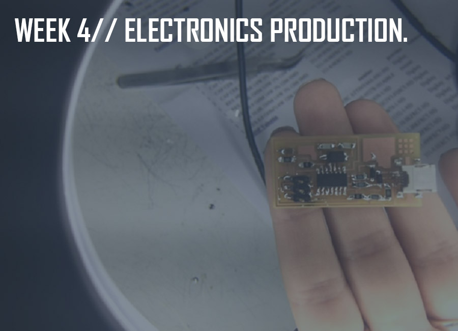
This week's assignment was to make a PCB: mill a board, stuff it with components and program it.
We will be using these programmers through the semester to program the other boards we create, so the focus this week is on machining and making a programmer that programs other boards.
The FabISP we're going to make out of FR1 boards, is an in-system programmer for AVR microcontrollers, designed for production within a FabLab. It allows us to program the microcontrollers on other boards we make.
We started off with an introduction to electronics production with Neil Gershenfeld, through which we went over a list of basics for this electronics production task.
Reading about the role of the different electronic components first, is very helpful to understand how the boards work.
Before proceeding with the milling, it is important to:
-make sure the Roland modela machine and the board are clean.
-use double-sided tape to hold down the board and make sure its surface is completely flat.
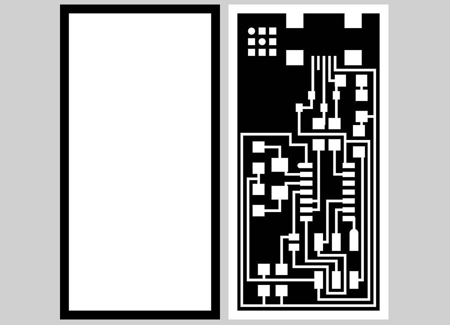
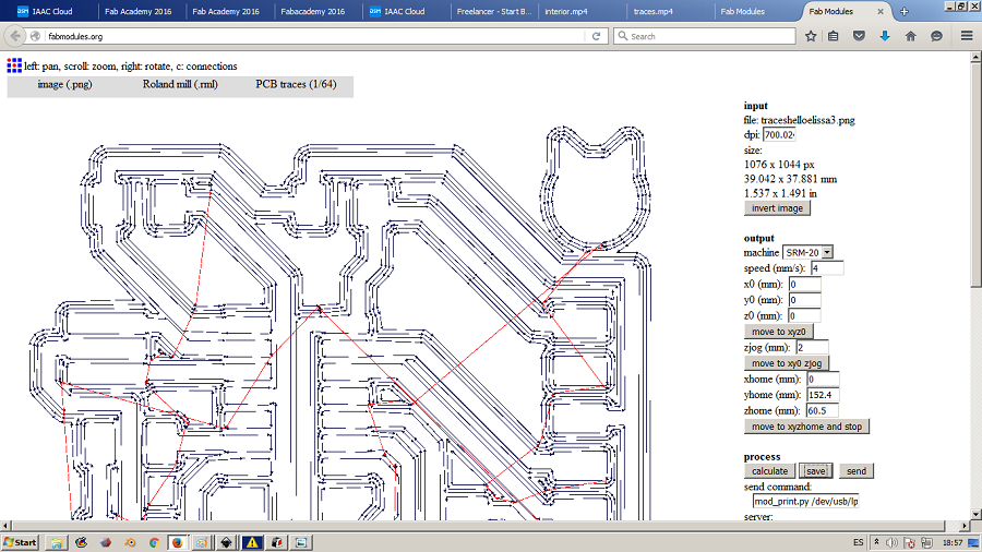
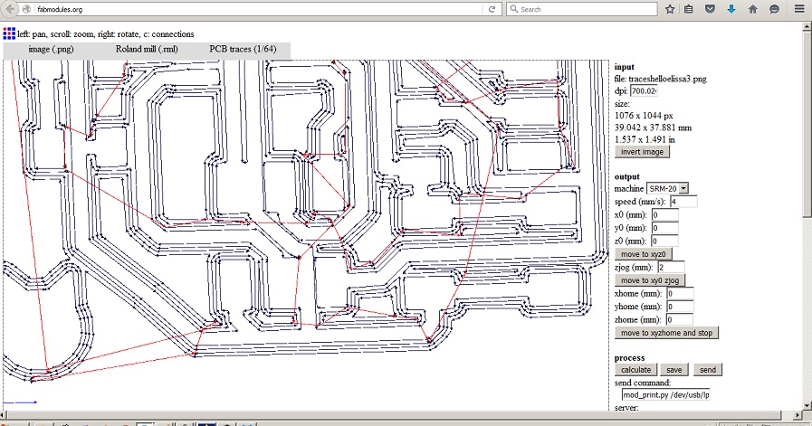
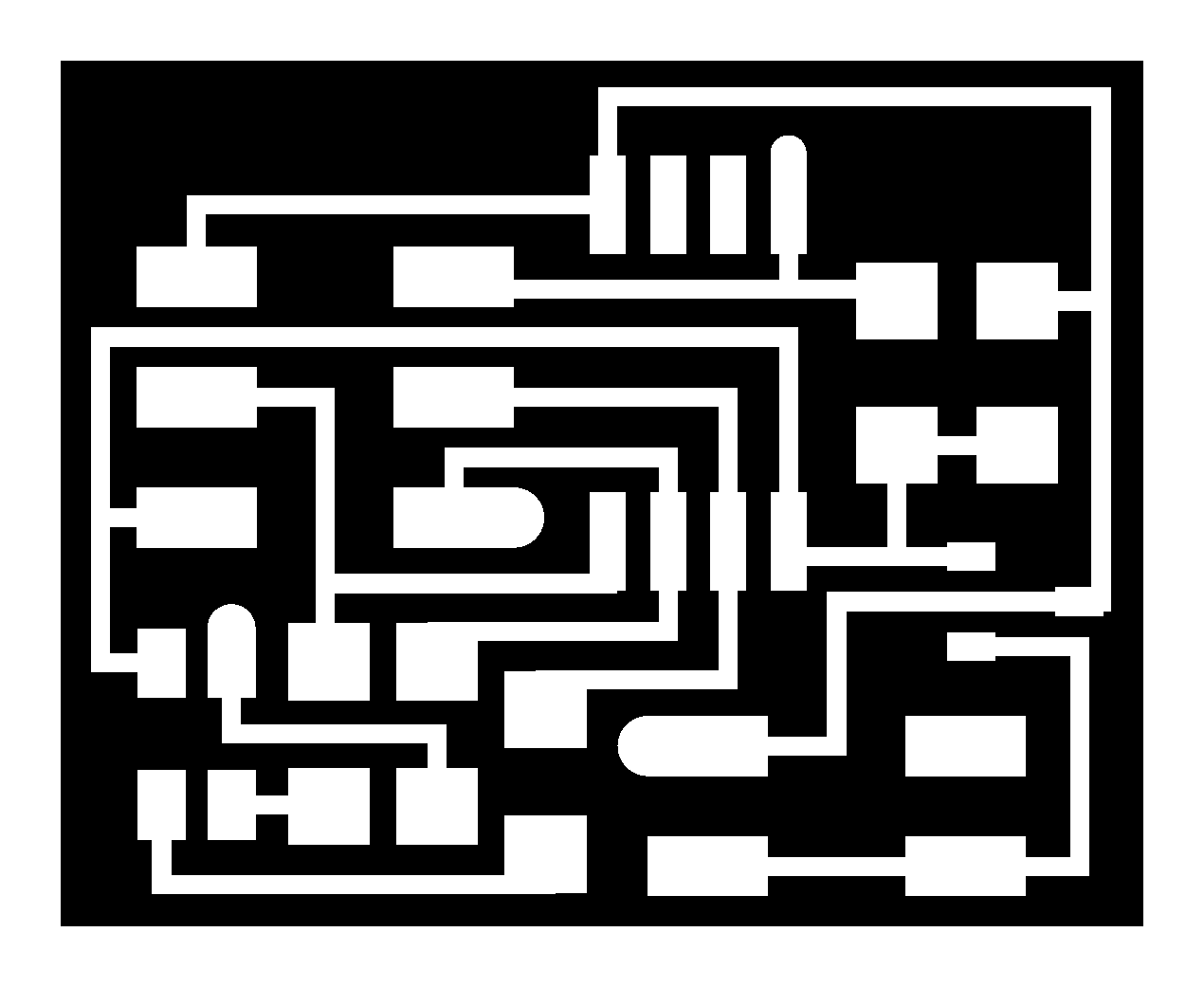
We can then download the traces png image to mill with a 1/64" end mill following these steps via the fabmodules. Create four offsets to make enough space to be able to solder.
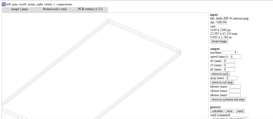
And the outline png image to cut with a 1/32" end mill following these steps also via the fabmodules. Make three depth passes of 0.5mm if the stock thickness is 1.5mm.
Traces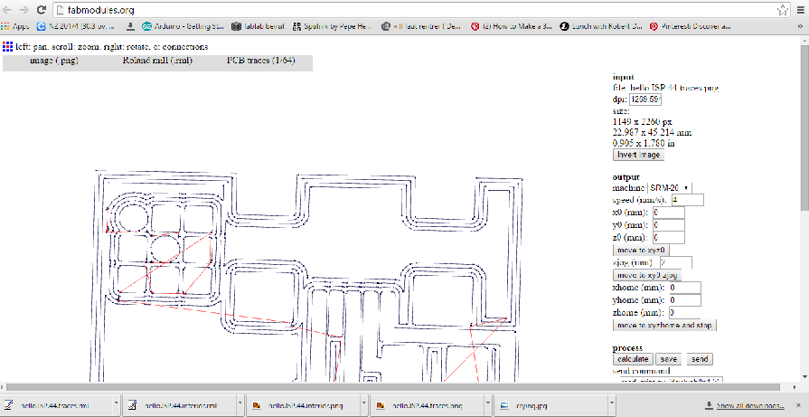 Outline
-Make input: images.png to output:RolandMDX-20.rml
- Load .png
- Fix the preset of the traces and the outline
- Make path
- Make rml
Begin with the interior.png as a test with the depth set to 0 just to make sure the board is flat and that it will be milled evenly, then proceed with the traces and finally the outline.
Press "cut" as seen on the image below, then "delete all", "add" your rml file and set your X,Y, and Z.
-click on View and set the origin X and Y and the Z point by lowering the bit so it slightly touches the copper plate.
Traces.jpg)
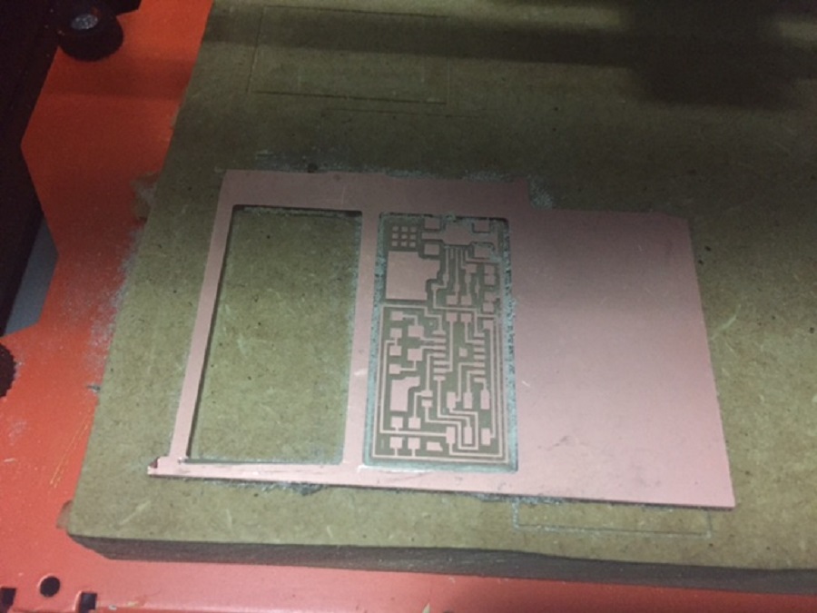
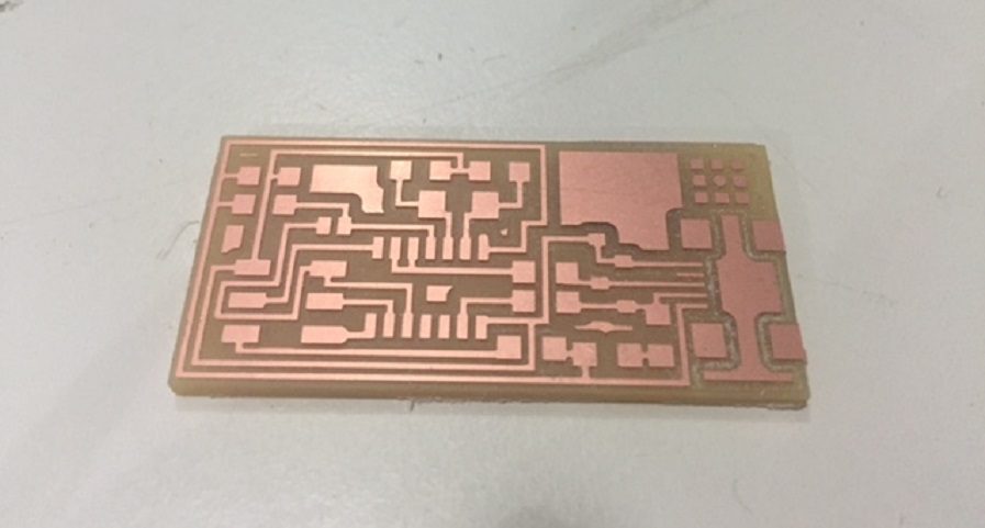
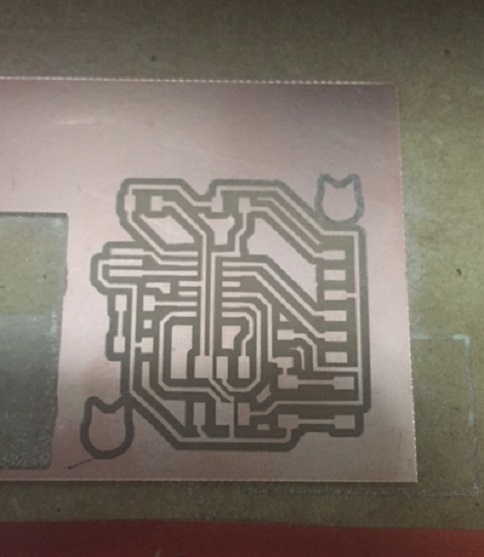
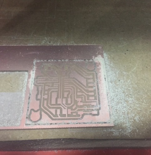
Repeat the same for the outline, changing the 1/64" end mill with the 1/32" end mill and using the same X,Y,Z values that had been set as origin (0;0;0).
Outline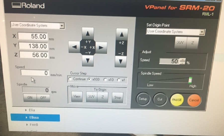 End Result
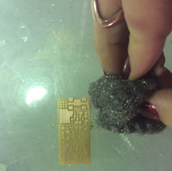
Once done, use steel wool to clean and then wash the board with water and let dry.
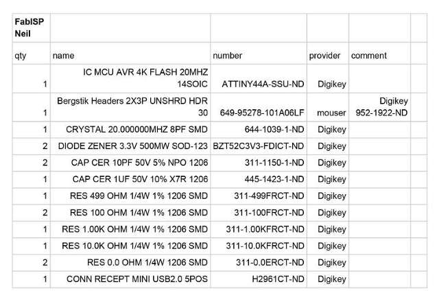
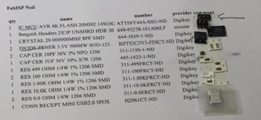
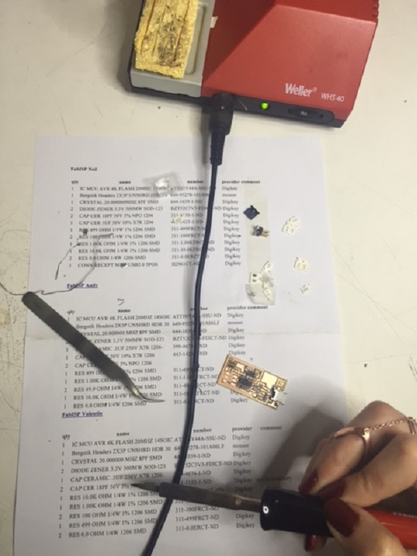
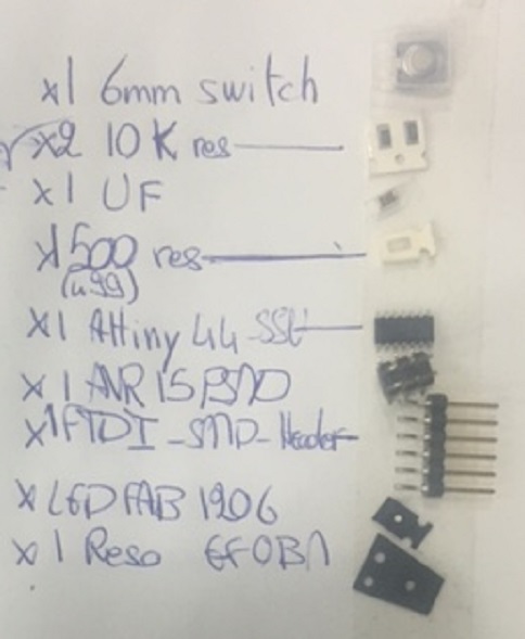
First gather the components corresponding to this list.
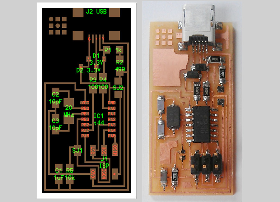
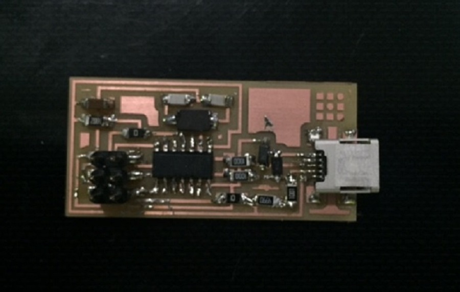
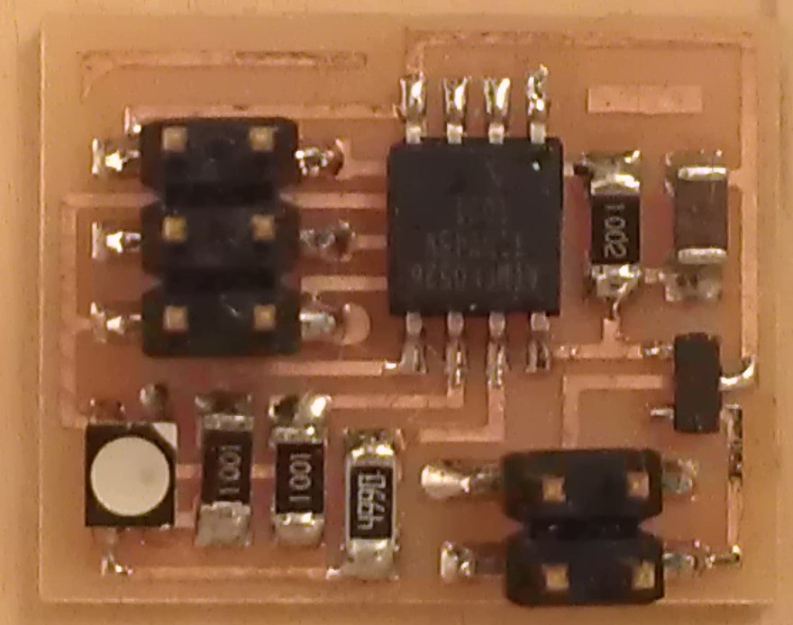
Then download the following diagram and a picture of a stuffed board to compare while soldering yours.
When soldering, it is important to:
-solder the mini USB header first and solder the microcontroller second.
-solder from inside to outside.
-make sure that the dot on the microcontroller, attiny44a chip, is oriented to the top left (if it's the same direction as the diagram in the image).
-mind the polarity of the diodes (from A to C) by placing the side with the tiny line on it over the "C" side pad in the diagram.
Here's a link to a helpful tutorial for soldering (be patient).
 It won't win the pretty contest
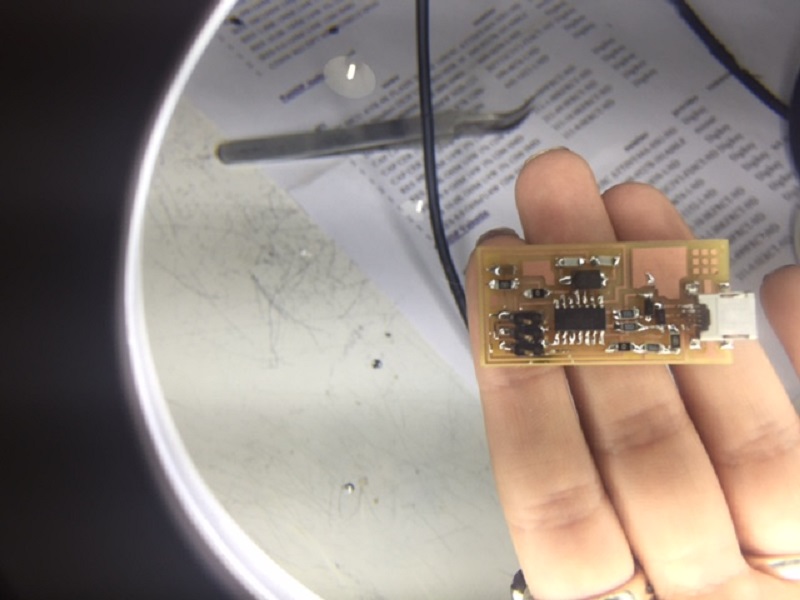
Before programming, it is important to make sure there are no short circuits by first doing a visual check of the board through a lense:
-the joints should be shiny and smooth.
-the tiny pins of some components shouldn't be connected with solder.
In my case, I had to tack down some components better by adding solder, and using desoldering braid, on the other hand to remove excess solder from some tracks that were connected.
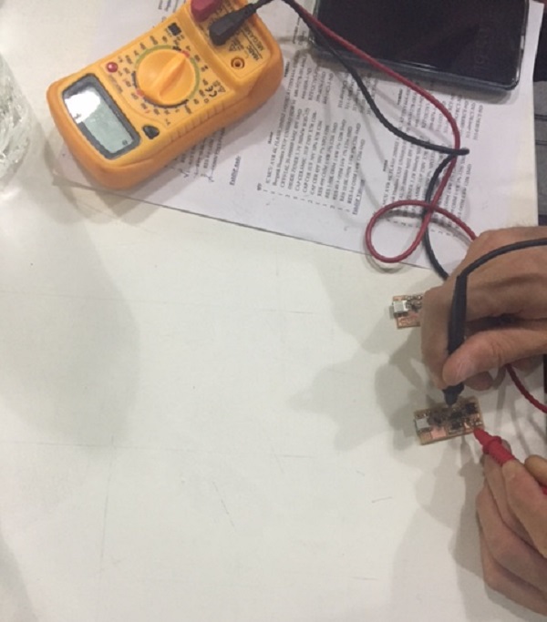
Then use a multimeter and check all the connections to make sure that:
- power and ground are not connected
- there is not a short on the power line.
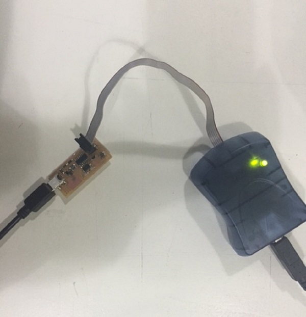
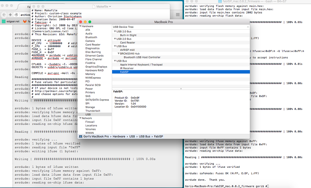
Once done with the short circuit troubleshooting, connect the programmer to your board with the 6-pole flat-cable and to your computer. You should get a green light and are now able to program it.
Next step, to program the FabISP is to install the necessary software for AVR programming and download the firmware.zip folder.
I used a Mac to program my board.
You then edit the Makefile, if using the USBtiny programmer or another FabISP by removing the "#" in front of the line with "usbtiny" in it, and adding a "#" to the beginning of the line with the "avrisp2" in it to comment it out, and save the Makefile.
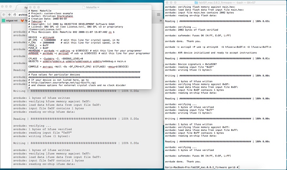
Open your terminal and move to the firmware directory by entering (if using a Mac):
cd Desktop/fabISP_mac.0.8.2_firmware
Enter the following lines in your command line window:
-make clean
-make hex
-make fuse
-make program
You can now remove the jumpers which correspond to the two 0 ohm resistors with desoldering braid to be able to use it as a programmer to program other boards.
You can download the Eagle schematics and board here.
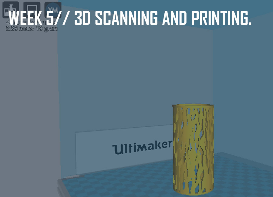
This week's assignment was to design and 3D print an object which cannot be made subtractively (milling or laser cutting) and to scan and 3D print (optional) an object.
As usual we started off with an introduction to 3D scanning and printing and went over a list of softwares and machines for 3D scanning and printing.
Here's a very helpful page about3D-Printing Design Rules to avoid facing problems such as warping (when the models bend and the corners come off.
Here are some solutions:
-Reducing the in fill(different sizes and patterns) the less dense the model gets (Choose different sizes and patterns, the hexagonal ones take longer not recommended)
-Reduce wall thickness
-Create pads int he corners of your model
-Brim - good to maintain the model on bed
-Raft - only good for model that's bottom surface only touches a little the bed
-Heat platform of printer
-Hairspray is very good to stick models in the printers bed especially heated ones (take glass and spray, good for 5 prints)
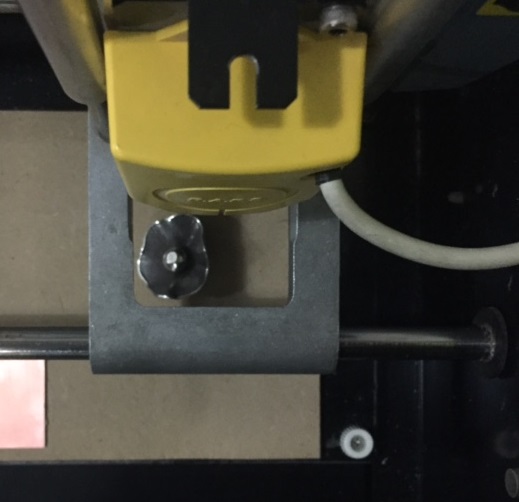
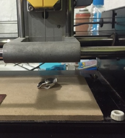
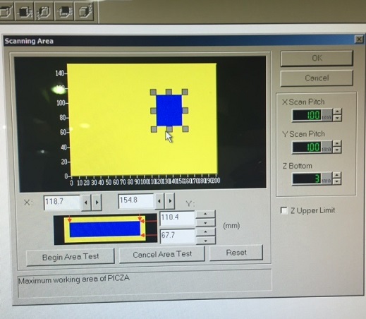
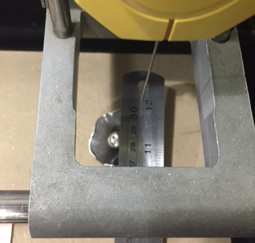
I started by scanning a very small object (top part of a ring) using the Roland Active Piezo Sensor (R.A.P.S.) techonlogy which allows you to scan data with a resolution down to 0.05 mm by detecting from the contact of the scanning head (needle) with the surface of the object.
Although it takes several hours to scan small parts, this technology is very handy when it comes to scanning glass, which is impossible using optical scanners because the light beams passes through the object without detecting it.
I proceeded by fixing the part on the plate, even though the tracing is very slow and shouldn't move the object, but since the scanning process is very precise, a 0,..mm could make a difference.
Then using the Dr. Picza software, I set my X and Y axis values, as well as the minimum and maximum values for the Z axis, and lowered the scan pitch to make the scanning process faster and save some time (because my model had a lot of small details).
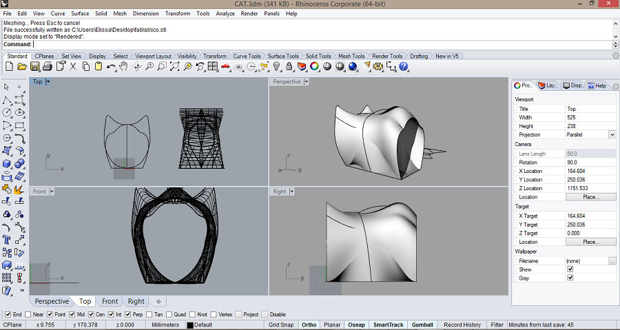
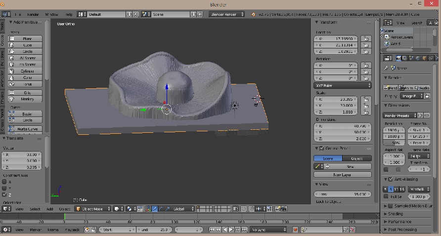
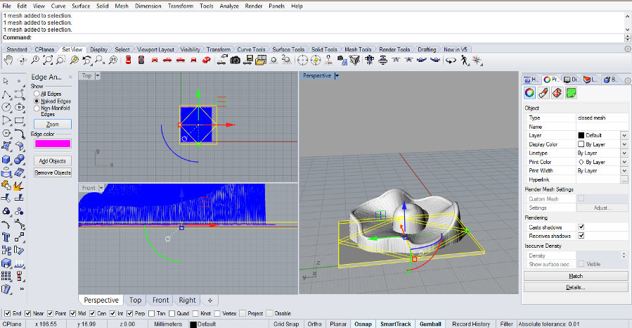
About six hours (and six cups of coffees) later, the scanning process was over and I was able to export the file as an .stl file (STereoLithography) and import it on Blender to prep it for 3D printing.
Rendered view of the scanned object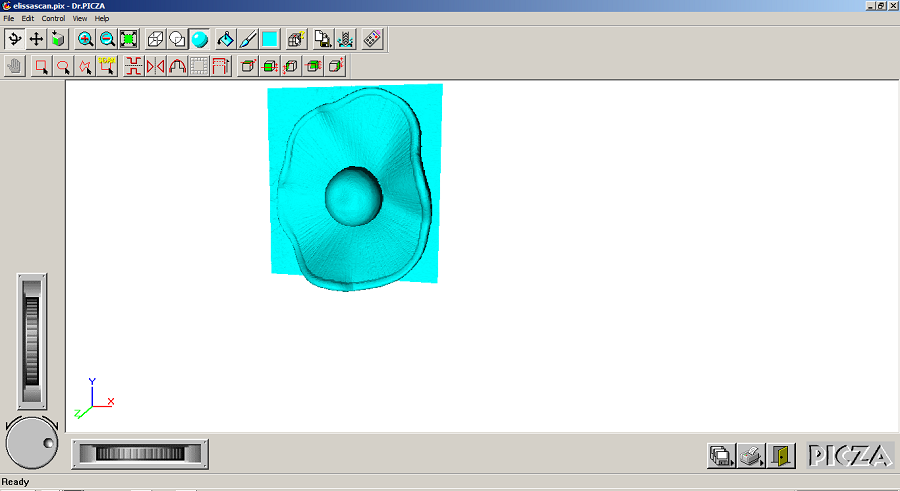
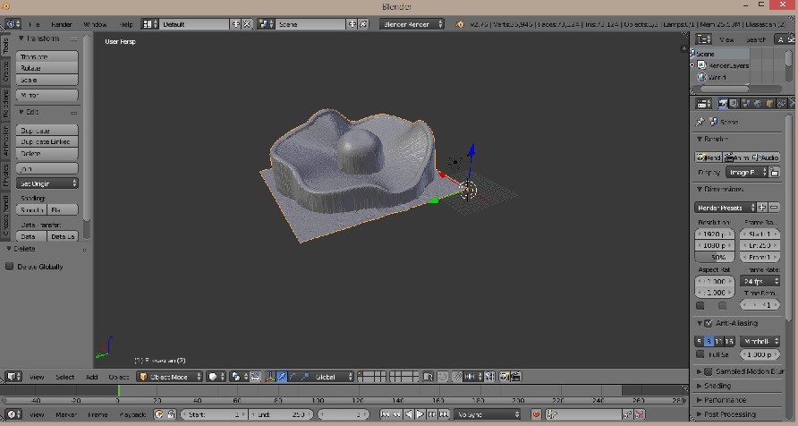
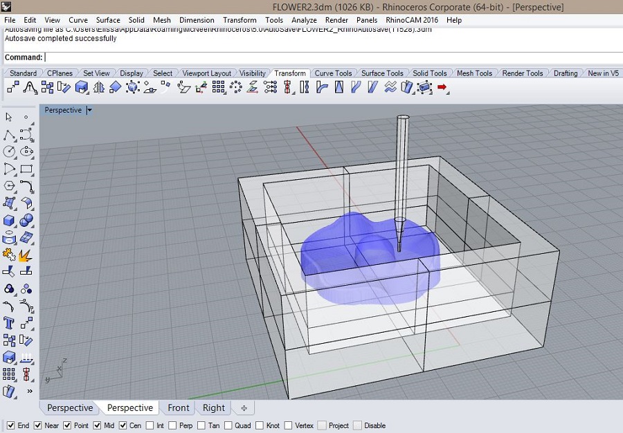
Using the Blender software, I created a box by going to mesh cube, and placed it on the bottom side of the model slightly intersecting it. I then did a boolean difference operation by going to modifier, and ended up having a closed object ready for 3D printing.
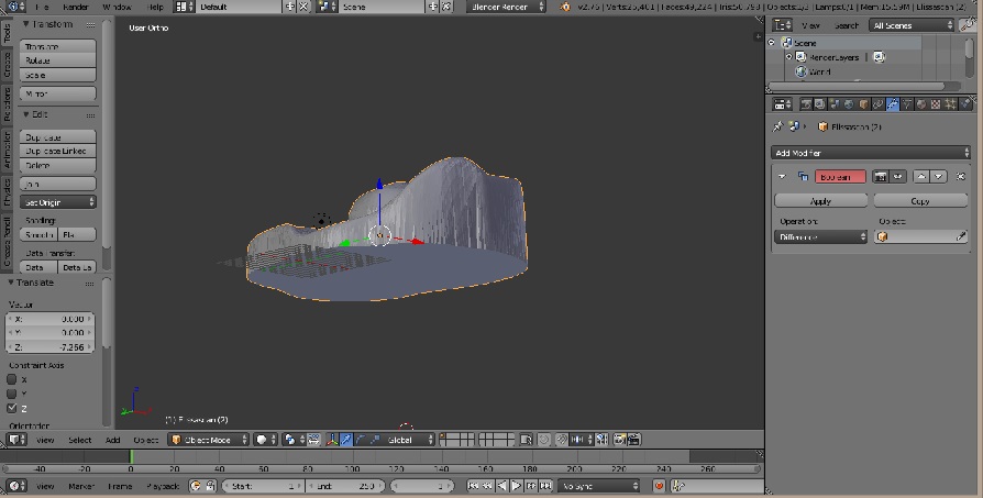
Here are the Blender file and the STL file for the flower model.
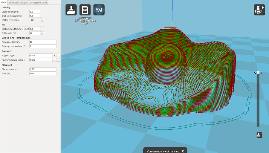
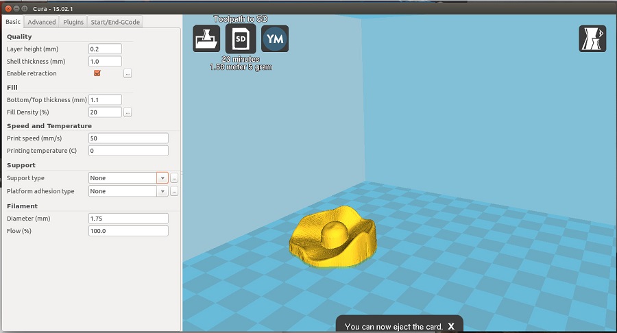
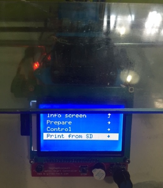
Once ready, I loaded the .stl file into the Cura software provided with the Ultimaker and modified the settings for printing it using PLA material.
To have better printing results, I set the fill density to 20% which should be a minium.
The speed shouldn't be set too high either.
Some other manual tips for ensuring better printing results by avoiding warping (bending on the corners) is to either, spray (hairspray) the plate, preheat it or use some acetone.
 Insert the SD card to select your file
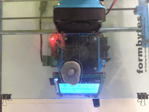 End result
I'm going to modify it as to serve as a head-piece and try printing it on a larger scale.
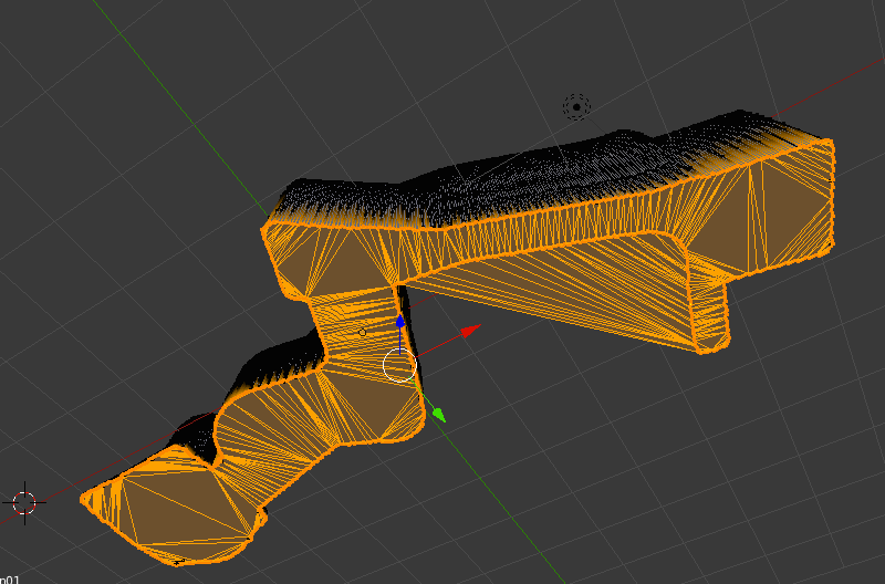
We've had a chance to have a very helpful tutorial with our instructor Ferdinand Meier using Blender to fix meshes for 3D printing.
It is a manual procedure but pretty effective and easy.
After importing your .stl file, here are a few steps to follow:
- set origin to geometry
- shift S selection to center
- shift S selection to cursor
- hit tab to go to edit mode then deselect
To select the open mesh to delete:
- in the bottom tab, select non manifold
Screenshots of the tutorial provided by Guillaume Teyssie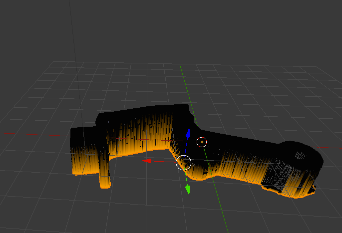
- select one vertice then ctrl i to invert then hit x and click vertices to delete
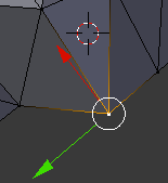
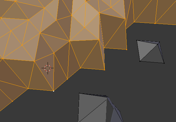
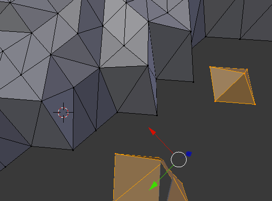
- then select non manifold and alt F to check once again for open mesh
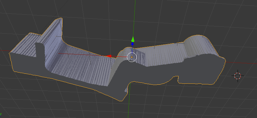
- tab to select all then hit G Z then align top line of model with red line
- shift S cursor to center
- shift A mesh/cube G Z 1
- shift S set origin to 3D cursor
- modifier/ boolean/difference/apply
- select cube X to delete
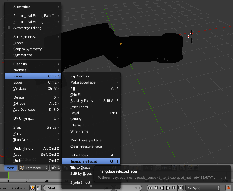
There are three ways to try to fill open surfaces:
- f to fill
- alt + f to beauty fill
- Mesh/Faces/ triangular faces
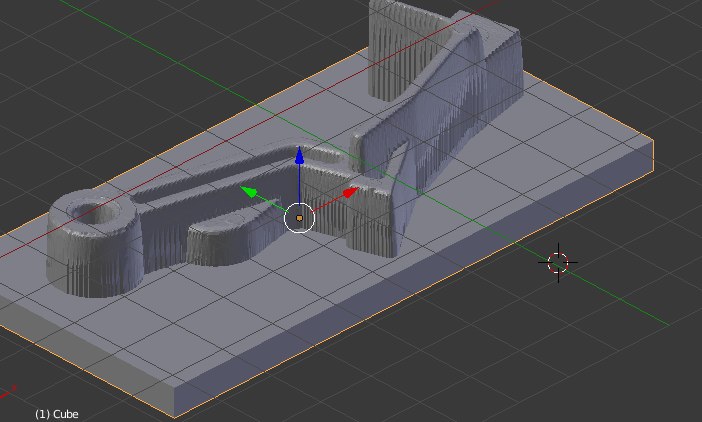
Before starting, here are a few important tips to preparing your Rhino model for 3D printing.
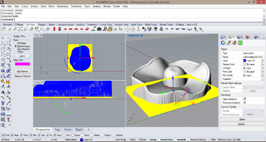
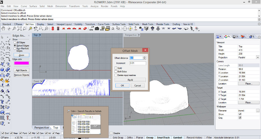
Another way I tried for cleaning the meshes of my scanned object, was on rhino but this time keeping the hole in the model that would appear as a mold.
I followed a few easy steps:
- first create a box as to intersect with the mesh
- use the mesh intersect command
- use the split command
- delete the unwanted parts
- offset the mesh to give it a thickness for 3D printing
- Save the file as an .stl file to send it to print
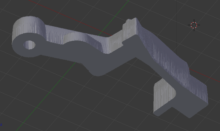
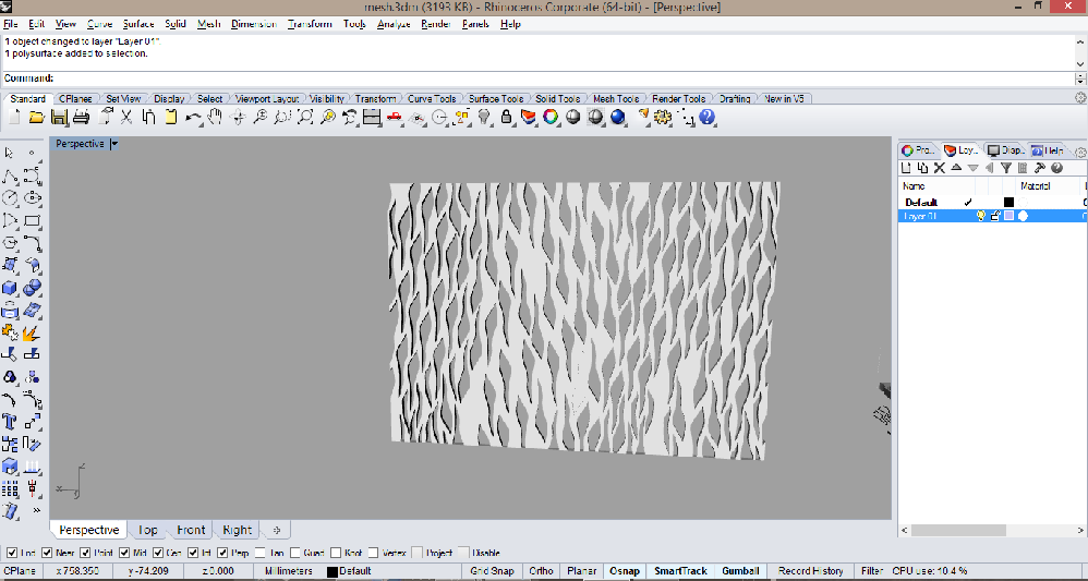
For the second part of the assignment, I designed a part (that could not be made subtractively) using rhino, and that would serve as a part of my final project prototype.
This piece should connect the different-sized modules of the prototype. By stacking them inside the tube, the flexible skin should take shape accordingly (using filaflex material).
(If I get the wanted results when it comes to flexibility, I'll redesign it in a way it could hang from the ceiling.)
I started by creating a 3mm thick box, drawing the desired pattern using control point curves and then extruding them. I then made a boolean difference opperation to get a perforated polysurface.
I wrapped this polysurface around a circle in order to create a tube by going to transform/ flow along curve, knowing that the lenght as the surface is equal to the perimeter of the circle.
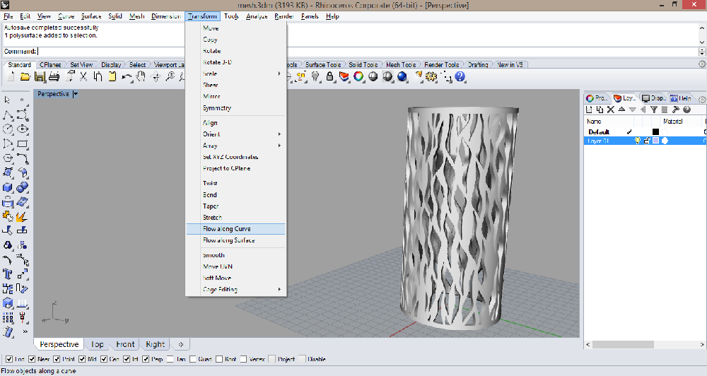
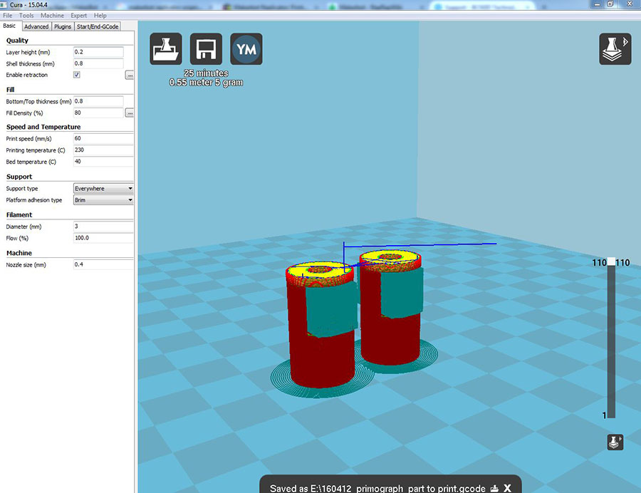
I then loaded it as a .stl file on Cura to get an approximate time of printed it will require and for checking the layers.
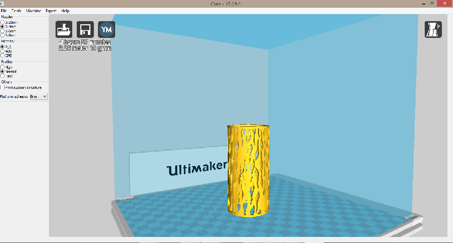
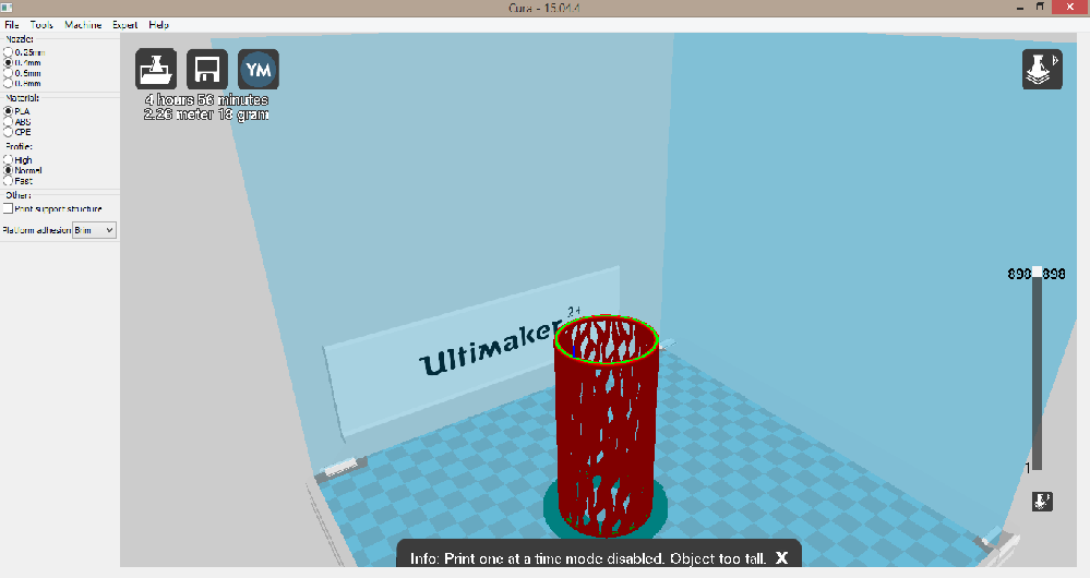
The actual diameter of the tube is 4cm and the thickness 3mm, but I eventually want to print a 15cm diameter tube.
I'm going to 3D print this part by the end of this week to check its flexibility and the accuracy of the printing and change the parameters accordingly.
Here are the links to download the Rhino file and the STL file for the model.
I also got to experiment with different 3D scanning softwares starting with Skanect which is a very user-friendly software, using a kinect sensor camera and creating 3D meshes in a matter of minutes.
You can download the Skanect Guide to all the exact simple steps we followed.
This 3D scanning procedure is based on photogrammetry which is the science of making precise measurements from photographs. The output produced from photogrammetry can be, among other things, 3D models of real subjects, including people and animals.
The downside is the hardware requirements. With high res images and great numbers of them you need a lot of RAM and CPU cores to render a model in reasonable time.
The bounding box should contain the entire object to scan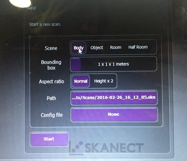
Skanect scanning trial from Elissa Sophia Assaf on Vimeo.
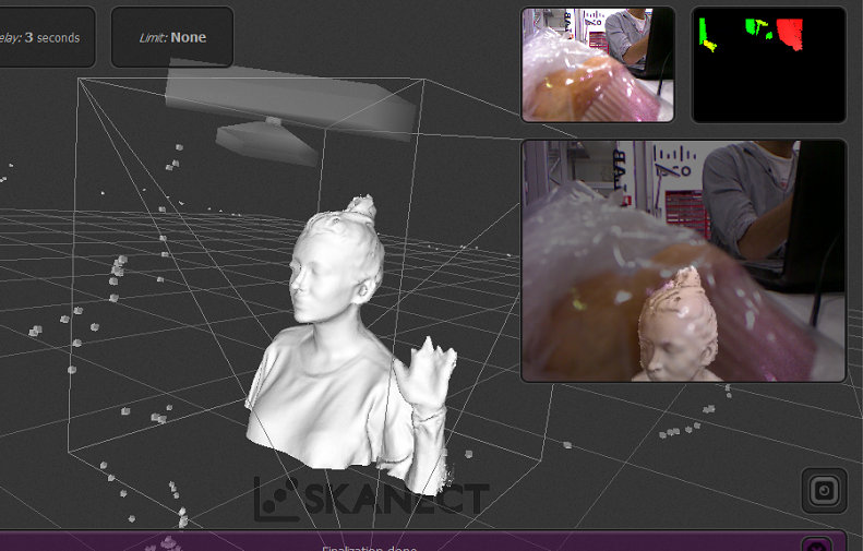
As you can see, the scanning process wasn't very successful because my movement was fast and inconsistent and the kinect wasn't stable.
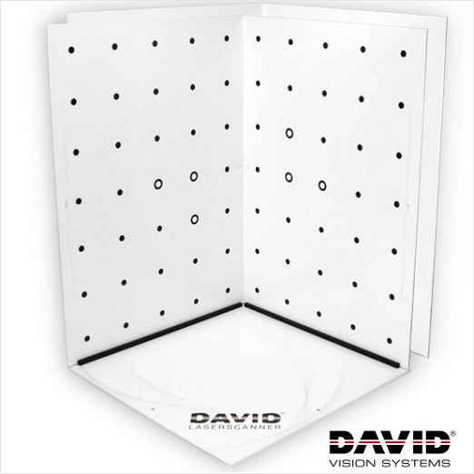
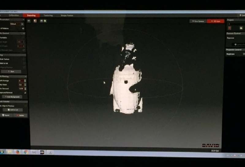
I then tagged along with two of my classmates who were setting up the David Laser Scanner. We first proceeded by printing out the two sheets of calibration pattern to calibrate the camera with the background using the software but we used the Structured Light Scanning (SL) which is 3D scanning with a video projector instead of the laser.
The idea behind the structured light scanner is that the projector covers the object in various patterns in quick succession as the camera and software record the changes to map the given face in 3D.
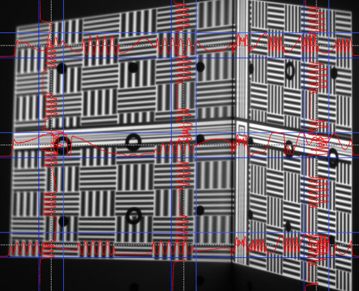
We encountered difficulties doing so, and ended up changing the webcam with another pro camera and the operation was successful.
We then removed the calibration panels (since we used a projector and not laser to scan).
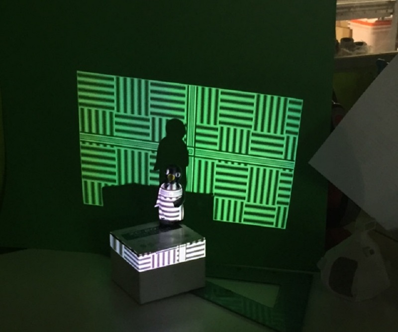
After calibrating, the second problem we encountered was the poor quality of the mesh produced by the scan, and we figured it was because of other exterior components such as the surroundings whereas it wasn't dark enough (although we had turned off the lights, there were still lights on in the rest of the lab).
Another problem is the color of the object, in this case (see pictures below) black which is the color of laser in use was hard to detect.
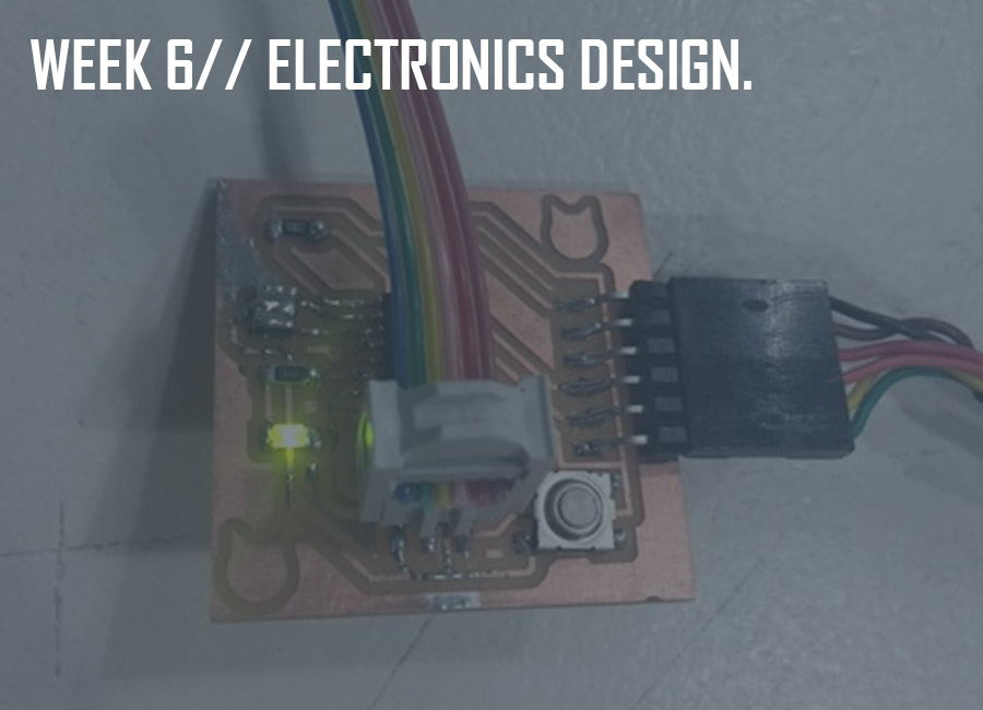
This week's goal was to redisign the echo Hello-World board we had milled, soldered and programmed during the electronics production week, and to add (at least) a button and a LED.
We started off the week with an introduction to electronics design and then went over a list of components and pcb board drawing softwares, with Neil Gershenfeld.
You can also download the book The Art of Electronics here.
Our tutor Ferdinand Meyer also recommended a couple of tutorials of which a schematic design tutorial, and a printed circuit board tutorial which were very helpful as well.
The steps to follow were: drawing a schematic/ placing the components/ rooting the traces/ simulating it/ fabricating it.
The following is a list of the components that were used and this is a link to their specs:
- 6-pin programming header to program the board
- Attiny44A microcontroller: once the microcontroller is programmed, the program is stored in non-volatile memory.
- FTDI header for power supply and computer connection
- 20 MHz Resonator external crystal clock generator
- Capacitor for a better quality input current
- 10K Resistors
- LED (Light Emitting Diode)
- Resistor to reduce led applied voltage
We started by downloading Eagle, which is a user-friendly software for pcb drawing, and the Fab library of components provided to make the board.
Copy the Fab library file into the Eagle/lbr folder in order for it to display between the libraries when you launch Eagle.
Make a New Folder under the PROJECT folder, name your project, then right click and select NEW- SCHEMATIC to start drawing.
After adding the components from the fab library, you can name (command on left-bar) the labels (command on left-bar) to connect components without routing the wires on the schematics file.
Schematics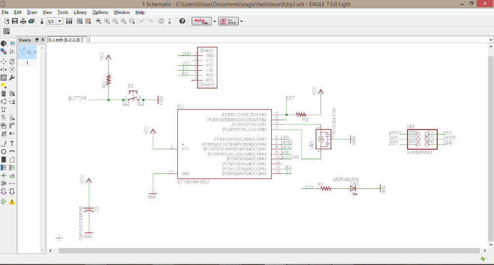
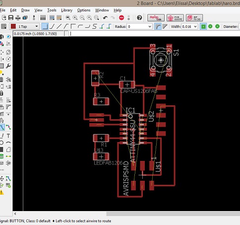
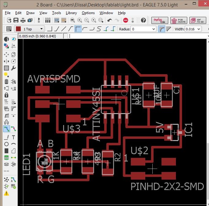
To switch to board view, go to the top menu/File/switch to board.
On the board view, yellow traces will be displayed to assist in the routing phase.
Before making routes between components, adjust the granularity of the grid, by clicking on the GRID icon in the board editor. A 0.05" grid, and 0.005" alternate grid is a good size for this kind of board. EAGLE creates a path for your routes and components to snap to, so to better control their placing, hold down ALT on your keyboard to access the alternate grid (after resetting the values). You'll be able to design routes and place components more precisely.
Board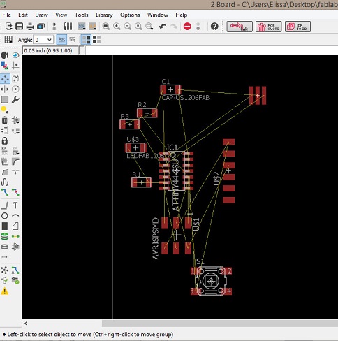
 Fail
Fail
 Fail
Fail
 Fail
Fail
 Fail
Fail
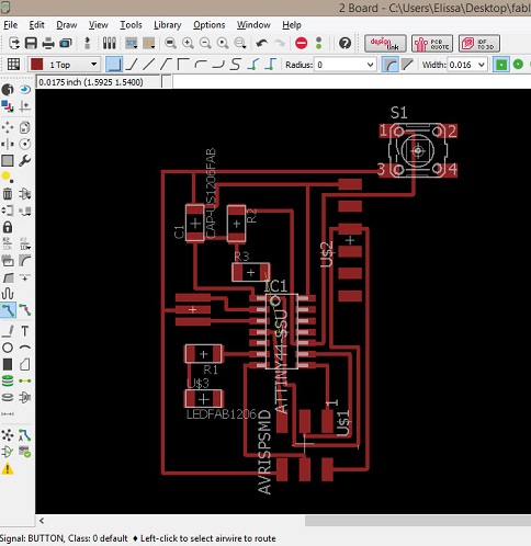
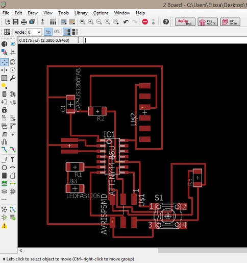
A note to keep in mind while redesigning the pcb board is that the design is going to have limitations if you don't want to add 0 ohm resistors and make bridges.
I had accidentally switched resistor 2 and resistor 3 and it took me some time to realize it, so I wasted a lot of time trying to connect the wrong components.
Almost there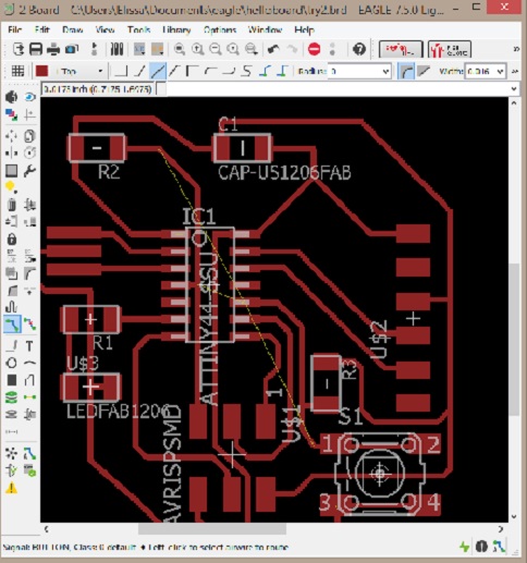
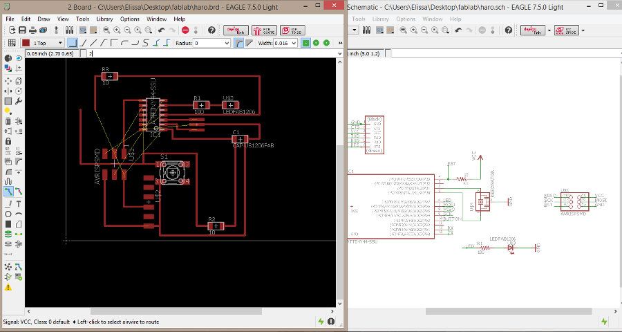
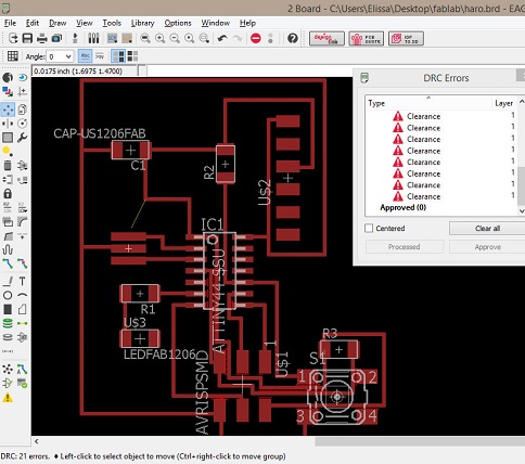
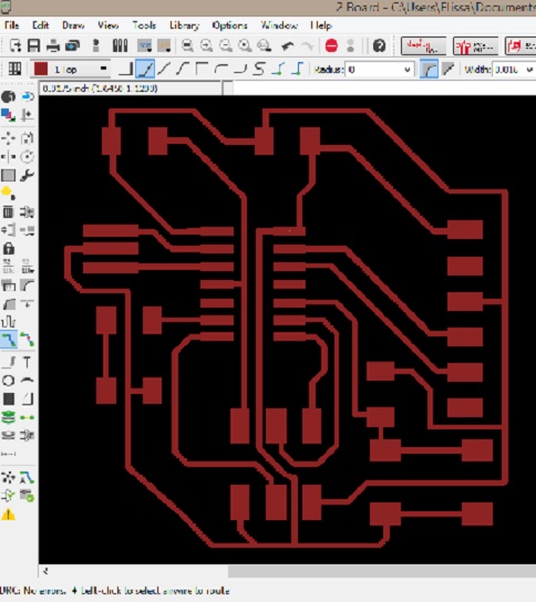
Once you've finished designing the board, run the DRC (design rules check), go to Clearance, and change the values to 16 mil (not to mistake with mm). It should display a "no error" message in the bottom left corner of the screen, if the routes are seperated enough for milling the traces, and if the wires are not overlapping.
Success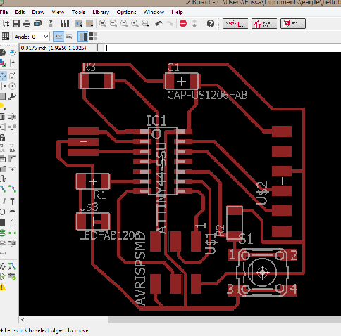
To create the "traces.png" file, turn off all layers except for the top layer which represents the copper routes.
After going to file/export/.png image, set the resolution to a minimum of 600 dpi (for the milling to be accurate and the close parallel routes not be connected) and tick the Monochrome option.
I then chose to create the outline on gimp.
Open the traces.png, go to Image/Canvas size lock the dimensions (to scale proportionally), add +1.6mm to width and height and click on center then apply.
You will then get a 1.6mm width frame.
Add a layer and then fill paint the layers accordingly with black and white to create the traces and the outline.
Export again as png keeping the same resolution.
Outline and Traces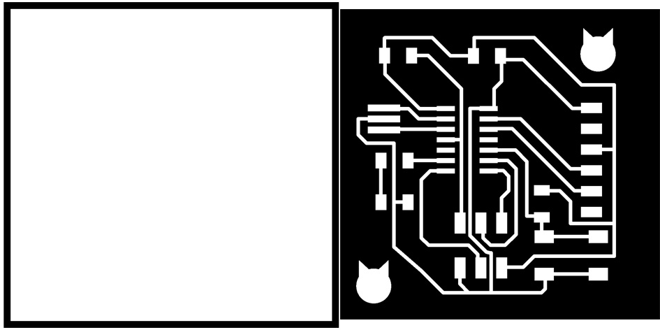
To proceed with the milling, follow the instructions as detailed in the Electronics Production week.
Outline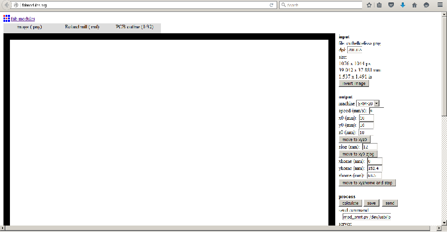 Traces
Although I had run the DRC command in the eagle board file and cleared all the narrow routes and fixed the overlapping, as well as set the resolution of the file to 700 dpi before exporting it, I still got connected routes after the tracing was done, in the area of the FTDI header.
Error Error Error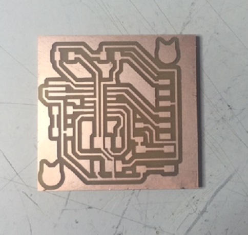
Ferdi helped me out with seperating the routes manually, with a cutter.
I then scrubbed it with steel wool to avoid short circuits, washed it with water and it was ready for soldering.
Human vs Machine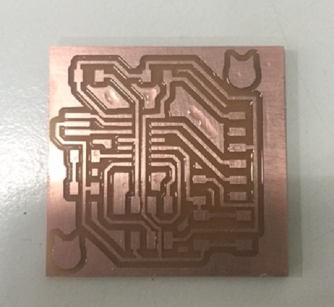
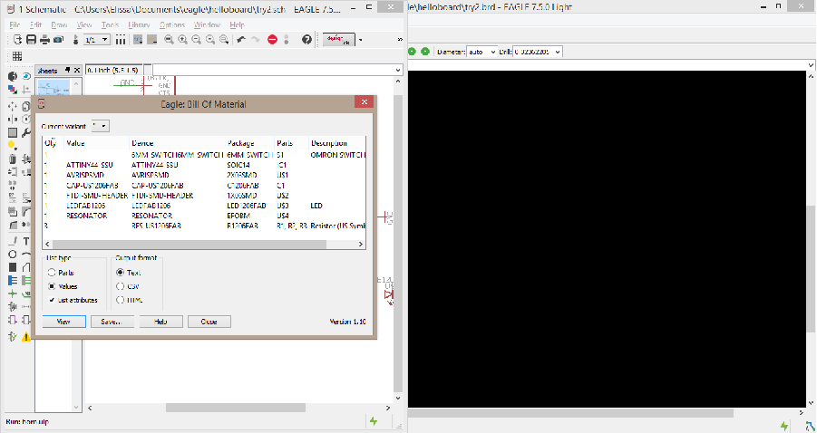
An easy way of getting the bill of materials for the board is to go back to the eagle board file and run the command "run bom".
Keep in mind when soldering, to solder inner parts and then outer parts from bottom to top, make the joints shiny and smooth, and mind the orientation matters for some components, in this case the microcontroller and the LED which have polarity.
The microcontroller has a dot on the top left side which should be connected to VCC.
The LED with the side which has a line is the cathode and connects to the ground.
The soldering went pretty much smoothly at th beginning but I had a very hard time soldering the resonator.
Don't Judge A Book By Its Cover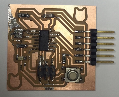
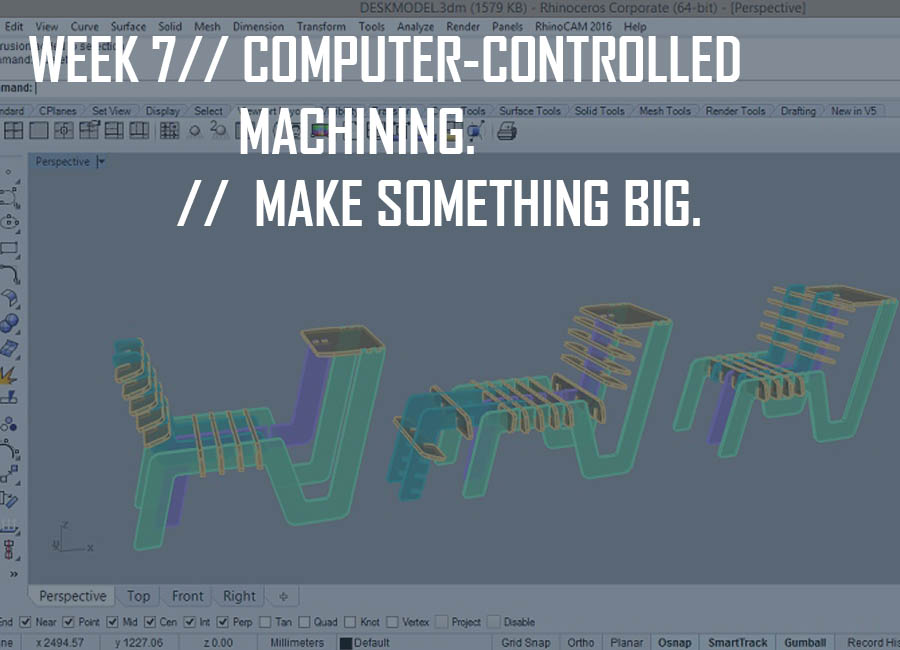
This week's goal was to "make something big" through computer-controlled machining, using:
- a 3D modeling software to design the piece
- generating a g-code (also check fabmodules for g-codes) to program the milling machine, using a cam program (3D toolcad calculation), of which:
hsmworks/ fusion360 and shopbot/ partworks/ rhino cam
- the SHOPBOT milling machine
We were also provided with a 2250x1225x15mm OSB board(oriented stand board).
As usual, we started off the week with an introduction to computer-controlled machining and then went over a list of calculation softwares, milling machines and tools as well as regulations.
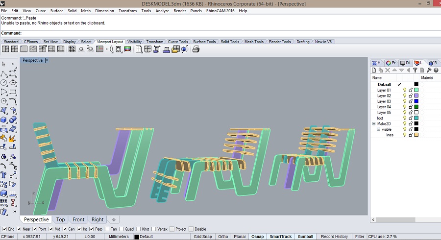
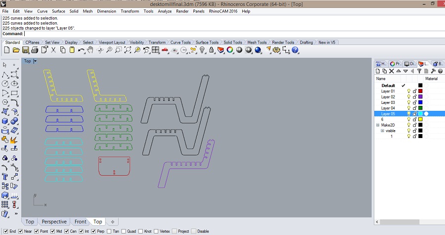
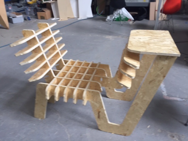
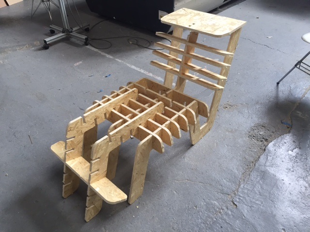
Since I'm lacking a working space at home, (and lacking space in general), I decided to design a desk, and eventually made it customizable to assemble as a chair or a long chair for better use of space .
I spent most of the time thinking the number of joints and their orientation to lock steadily.
3D model on Rhino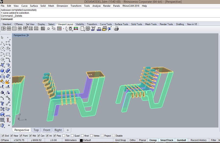
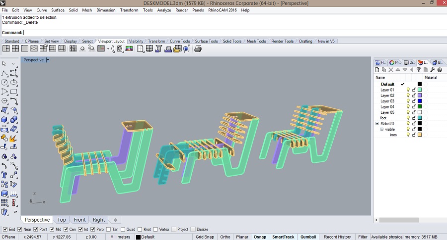
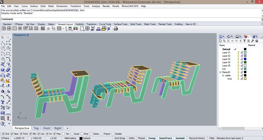
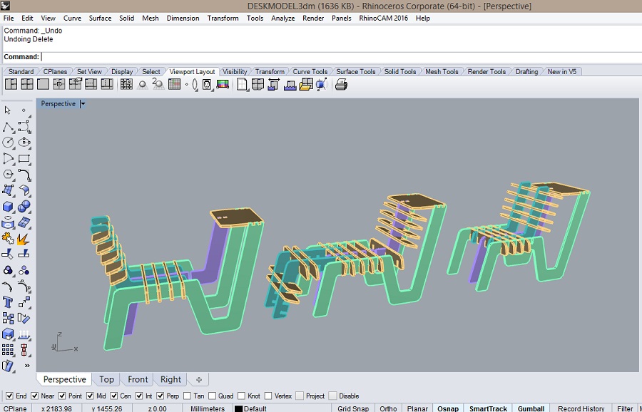
Since the millbits are round-shaped, it is impossible to have 90degree angles cut, hence the use of t-bone or dog-bone shaped joints.
It is also possible to add them later on once the file is ready in Partworks.
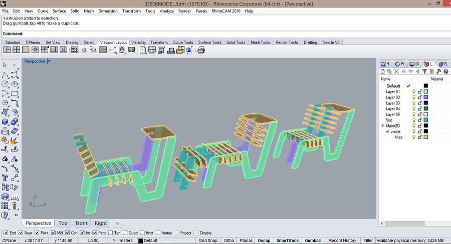
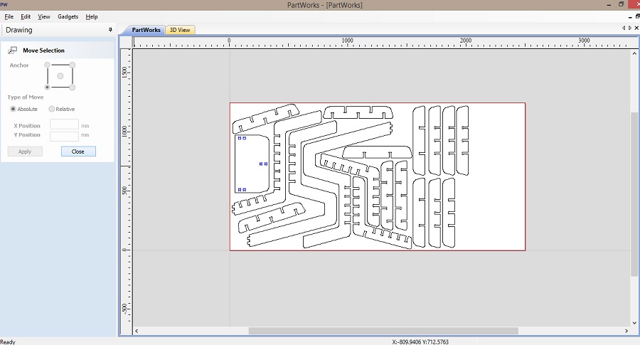
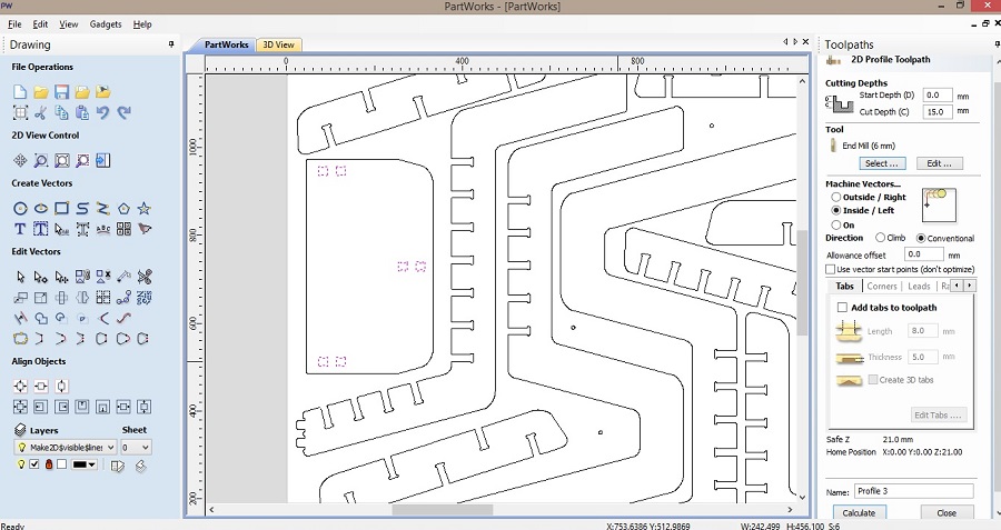
I then layed the pieces as they should be milled on the OSB board as a press-fit construction kit.
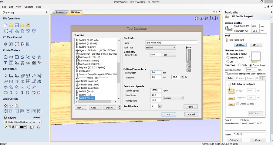
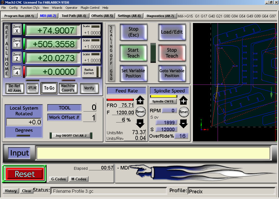
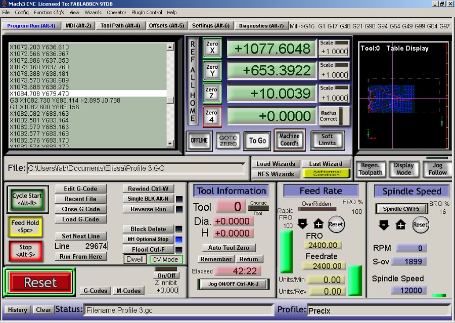
In order to send the file to mill, you should generate a g-code using a cam program, in my case Partworks.
After exporting the file as dxf on Rhino, open it in Partworks and set the size of the board as well as the thickness of the material.
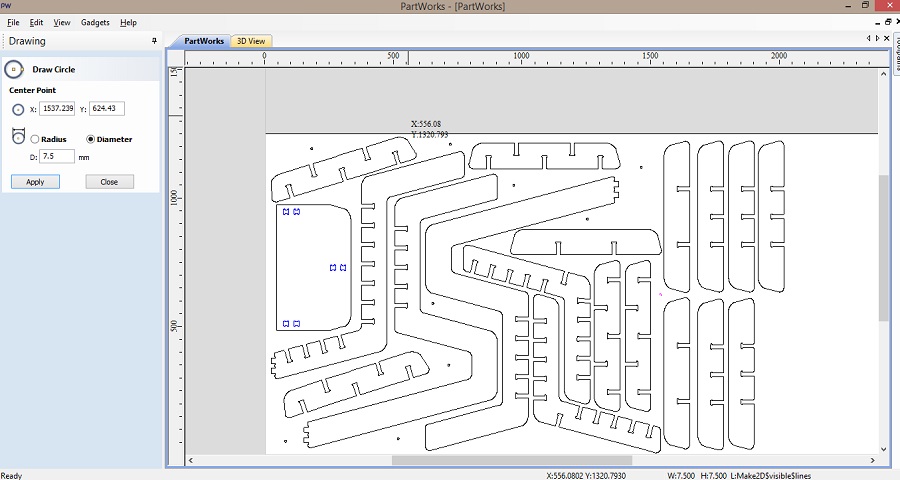
First go to "Edit Vectors"-->"Join Open Vectors".
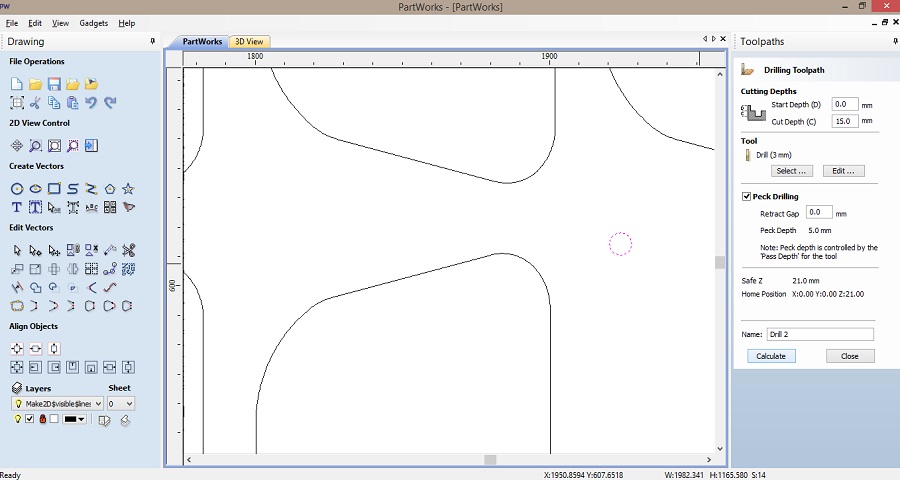
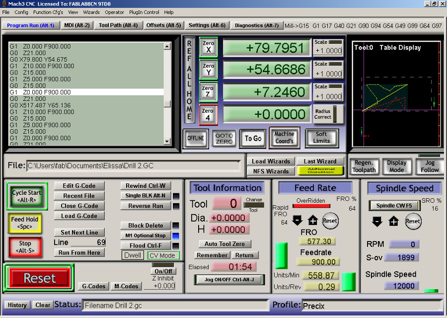
Create the drilling toolpath changing the tool to the drillbit, placing a fair amount of holes for screws to stabilize the board, and save it as drill g-code.
You then create the milling toolpath (Profile and Pockets: in my case I had just one pocket) change the tool into to corresponding millbit and save it as mill g-code.
It is important to place the right amount of tabs in the right location. An efficient trick is to align them.
You can find the milling parameters I used below.
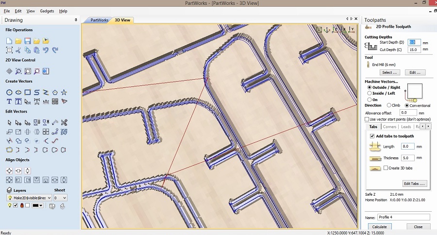
I was the first one to use the mars3 machine they had just installed in the lab so it was quite thrilling.
After uploading the file, I set the x,y,z axis to zero (mind the thickness of the board for the z axis) and selected the drill tool to stabilize the board on the platform of the machine, and then the 6mm milling tool after having put the screws in the drilled spots.
Drilling the screws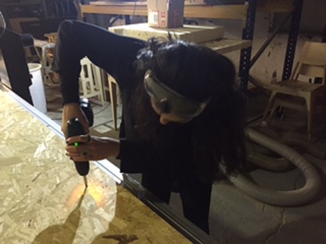
 Memorizing the code line to resume the next day
Once done, I had to remove the tabs using a chisel and a hammer.
After having sanded the pieces to remove the wood chips and give them a smoother texture, I assembled them in the three different ways I had designed.
The joints seemed to be wider although the test pieces fit perfectly well, but since I had designed all the joints in the right directions, the only part I could remill was the top part of the desk, the rest being stable enough.
Final Result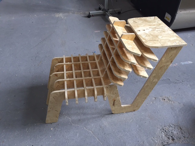
You can download the press-fit construction kit .3dm file and the drilling/milling G-Codes Partworks files here.
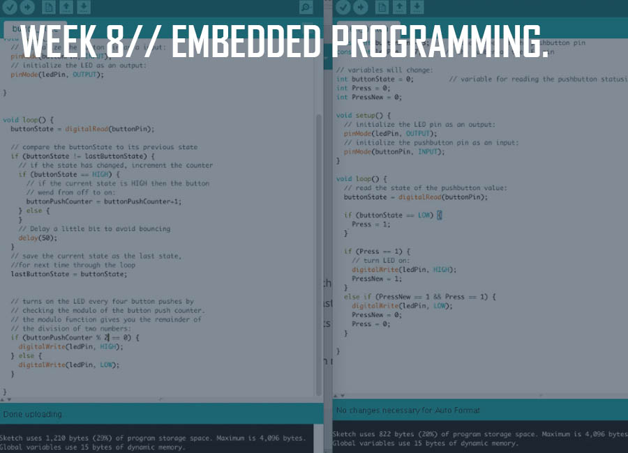
This week's goal was to program the board we had designed so as for the led to light when the button is pressed.
We started off with an introduction .
Since we were using Arduino IDE to program our boards, the first step was to download it and then download the ATtiny zip file.
1// In the Arduino folder, you then create a sub folder and name it "hardware" in the sketchbook folder and then copy the "ATtiny" folder from the "ATtiny-ide-1.6x.zip" after unzipping it, into the "hardware" folder.
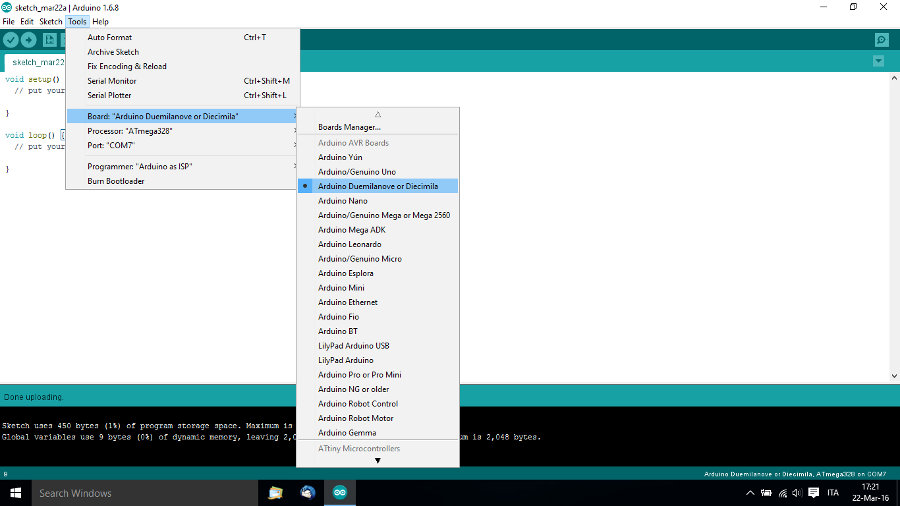
2// Restart the Arduino development environment and go to Tools -> Board menu ->ATtiny.
To power and connect the boards
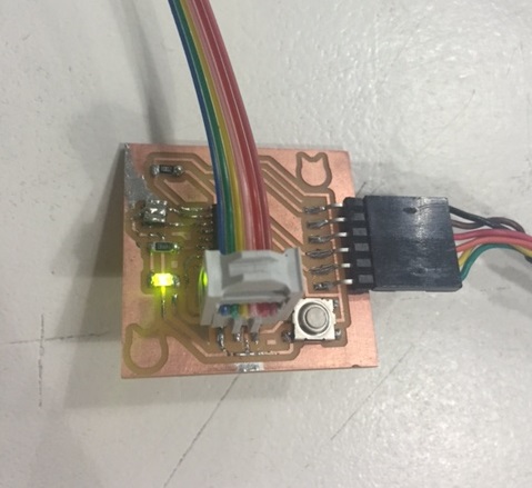
3// Make a 6-Pin Header (out of a 2x3 female connector and a 6 wire cable) to connect the Hello-board to the fabISP to load the program into it through the fabISP.
Make sure that the GND from the board is connected to the GND from the fabISP.
4// Connect the hello-board using FTDI cable to the computer to provide power.
5// Configure the ATtiny to run at 20MHZ (Clock->20MHZ).
6// Assign the fabISP as the programmer (it will appear once connected).
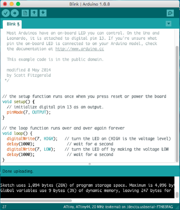
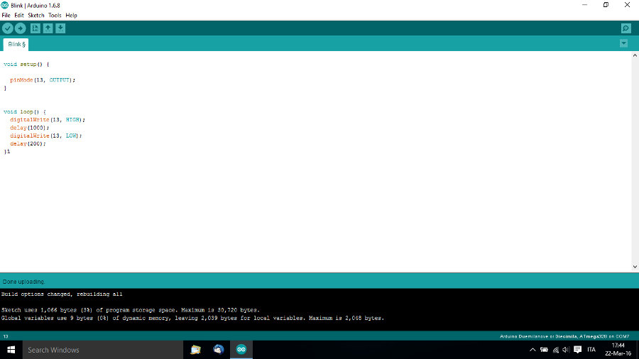
7// Go the Examples -> Analog -> Button.
8// Assign the Arduino pins to the corresponding microcontroller pins which in my case was pin 7 in arduino for the led pin 6.
9// Go to Tools -> Burn Bootloader.
When I first tried to program the button to turn on the led, I failed because I forgot to desolder the 2 jumpers from the fabISP (of course silly me).
Fail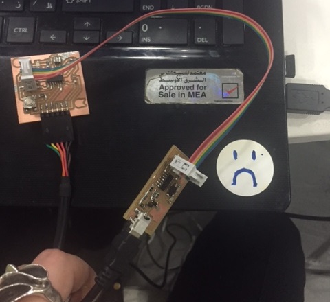
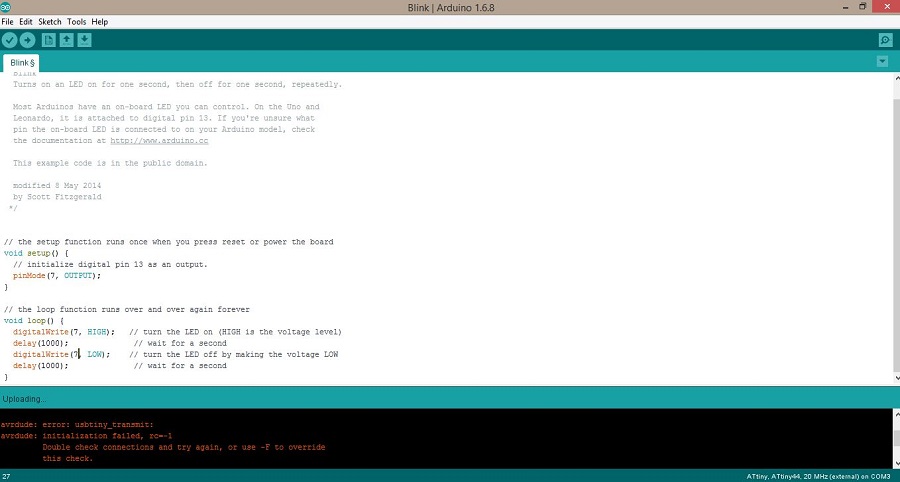 Success
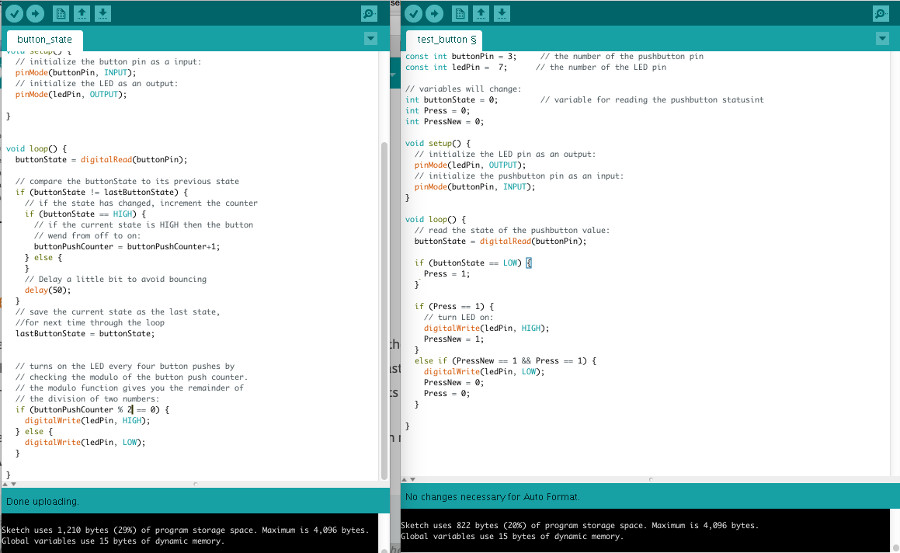
Programming the button was pretty easy but I wanted to try to program it as a switch too, which I did with the help of Santi.
LED board with programmed button from Elissa Sophia Assaf on Vimeo.
You can download the arduino files for the button here.
During the Machine Design week, I also got to use Python with a Raspberry pi with the help of Andreas Kopp who was working on automating the machine.
We also had a chance to have an Arduino presentation with Guillem after which we each played around with the different Arduino boards available at the lab.
Screenshots from the tests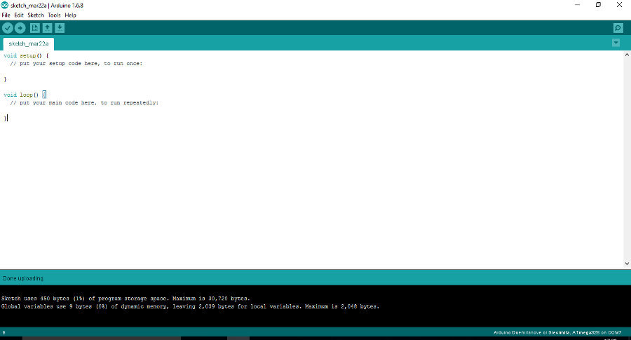
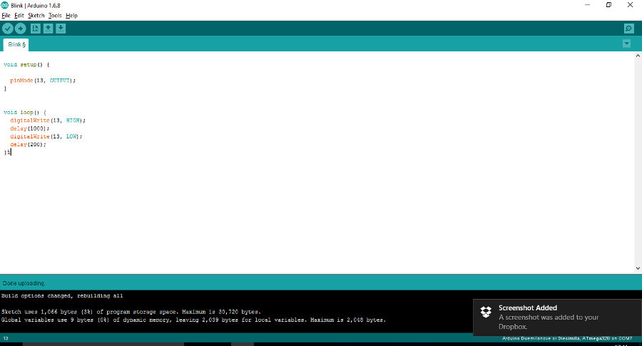
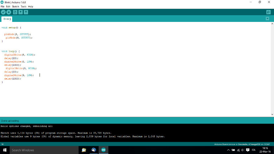
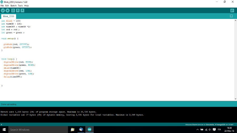
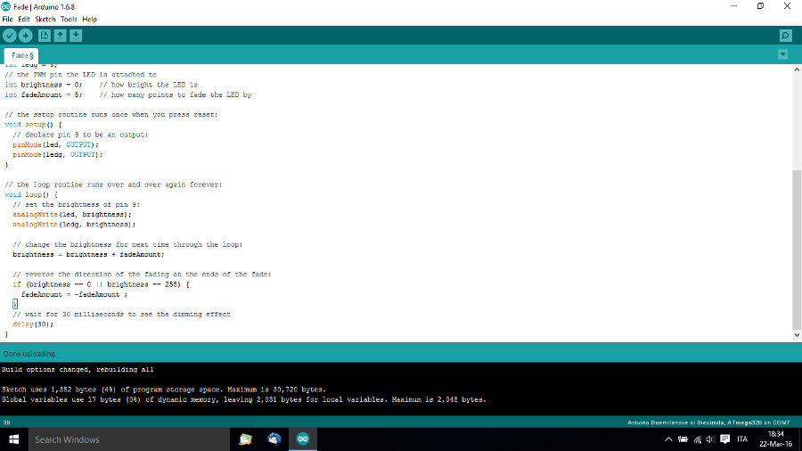
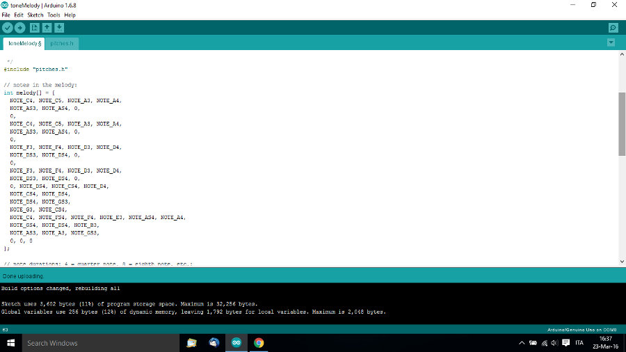
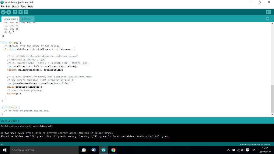
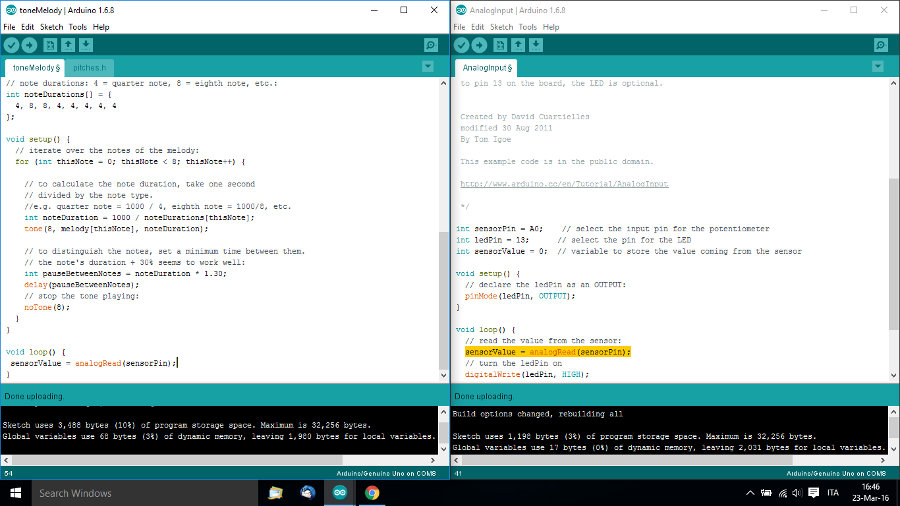
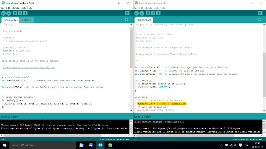
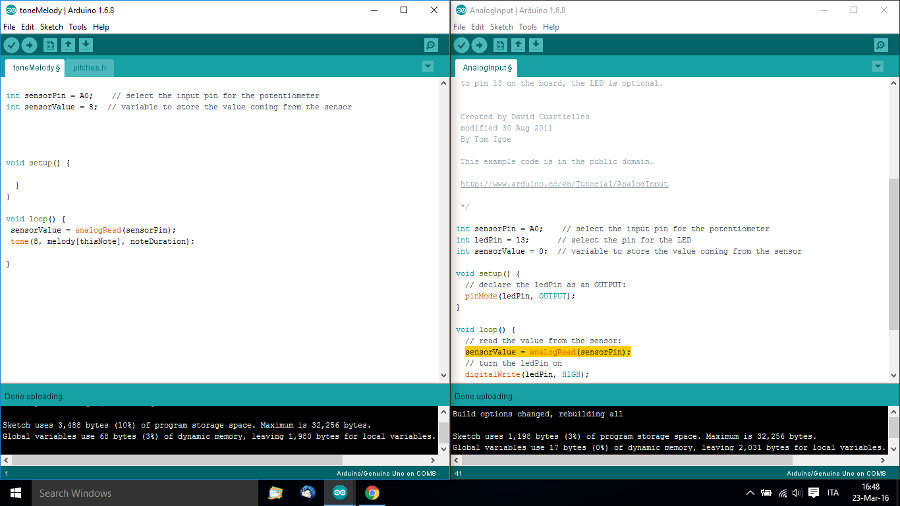
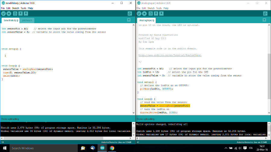
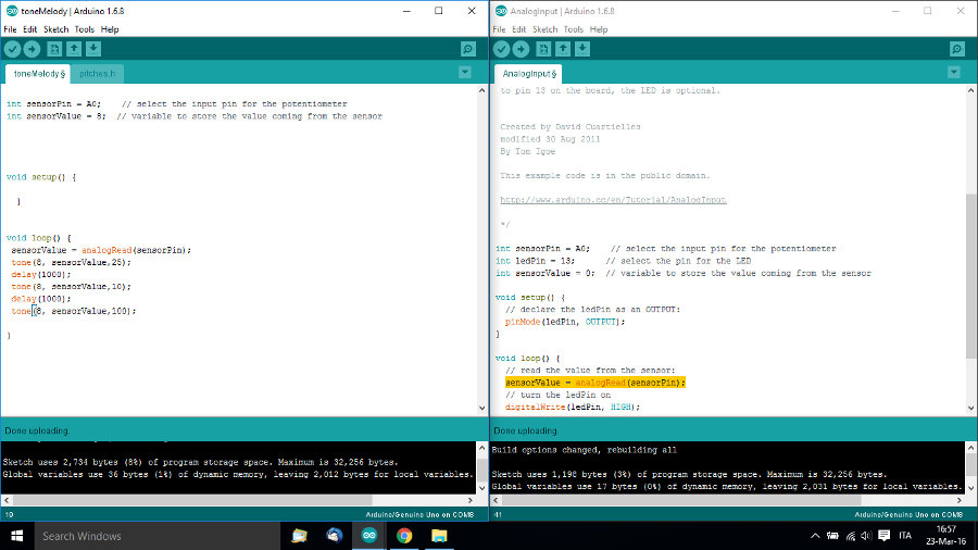
You can download the arduino test files here.
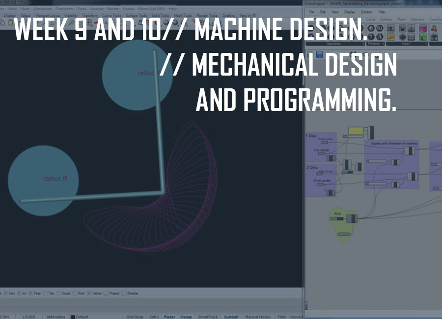
The machine design group assignment -which consisted in automating a machine with the end effector- was to be made over a period of two weeks, the first week dedicated to the mechanical design and the second to the programming part, the machine design.
As usual, we kicked off the week with an introduction to mechanical design with Neil Gershenfeld.
Group members:
-Eva Blšáková
-Norma Deseke
-Andreas Kopp
-Et moi
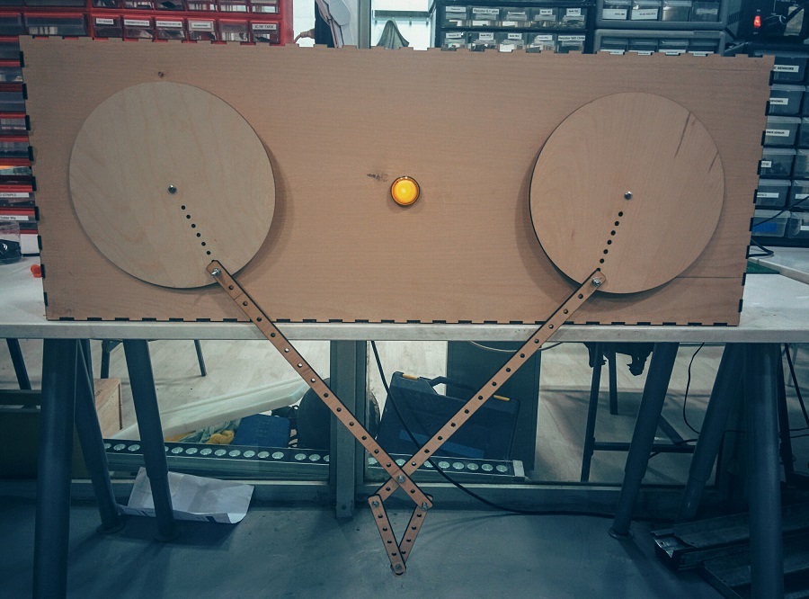
One inspiration for our project was the "Drawing Apparatus" by Robert Howsare, a primograph created from two turntables. Another stunning installation came from Copenhagen based artist Eske Rex who created a drawing machine generating beautiful artwork. Eske Rex: "Drawing Machine is a construction involving two pendulums, each suspended from a tower construction and connected through “drawing arms” and moveable joints. A ballpoint pen resting on a drawing surface covered with paper is mounted at the point where the pendulums come together. The pendulums are set in motion by hand, and their movements are represented on the paper. The Drawing Machine serves two purposes: In exhibitions where the movements of the pendulums affect the entire room, and the experience engages the beholder’s body. While the rhythmic repetitions cause the beholder to pause, the drawing emerges on the paper. And as a tool where investigations on the relation between time and movement."
Primograph powered by turntables :)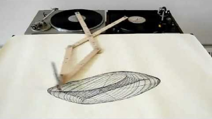
Since we were all outside Barcelona for the week, because we had already planned our trips back home according to the first given schedule, we actually only had a day to do the mechanical part for the machine.
We decided to go forward with a project Eva had previously worked on as part of a univesity assignment, which was a primograph.
Eva had already configured various complex patterns generated using Grasshopper as a plug-in for Rhino.
This kinetic machine though was not automated and only operated manually.
Here's the presentation of her first kinetic primograph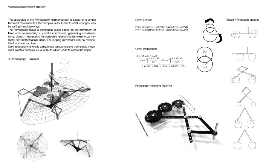
Software: Rhino Grasshopper and Blender
Test Machine: Epilog Legend Laser Cutter
Test Materials: black and white Acryl/plexiglass, 3mm thickness
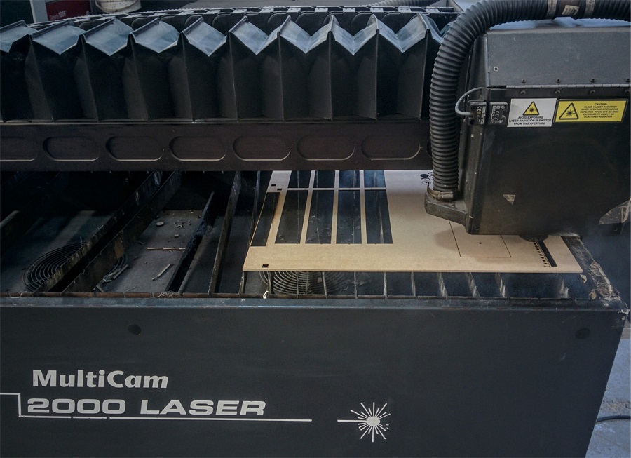
Final Machine: Multicam 2000 Laser Cutter
Final Materials: MDF Wood, 4mm thickness
Other materials: screws, nuts,
Eva´s research included the preparation of this Video of ITUS kinetic morphologies.
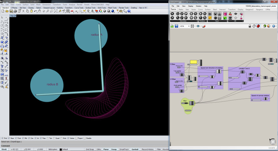
Primograph Grasshopper Simulation from Elissa Sophia Assaf on Vimeo.
Primograph Simulation from Elissa Sophia Assaf on Vimeo.
// First test: 3mm black acrylic: 15-100-5000 (speed/power/frequency) on Epilog Legend Laser Cutter (load file, press 8-->xy off, press go; move home manually; press 7-->adjust; press 9-->focus; press go)
The first test didn't cut through.
// Second test: we decreased the speed to 5%, still didn't cut; laser-cut same place twice with same settings: the cutting was successful but the edges were burnt, which would affect the wheels and translation of the movement.
// Third test: white acrylic also 3mm, 5% speed, we got a nice clear cutting edge.
While it worked in the final test, setting out to cut the whole box failed. This was either related to the uneveness of the machine surface base or varying material thickness.
The settings worked for some but not all parts of the material.
We decided to use wood for the arms and wheels, but based on previous tests, wood has a texture which renders movement less smooth, which would impact on wheels trasnlation of forces (movement).
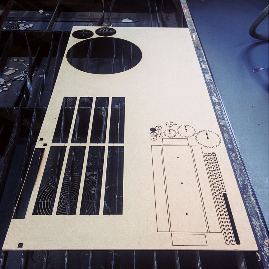
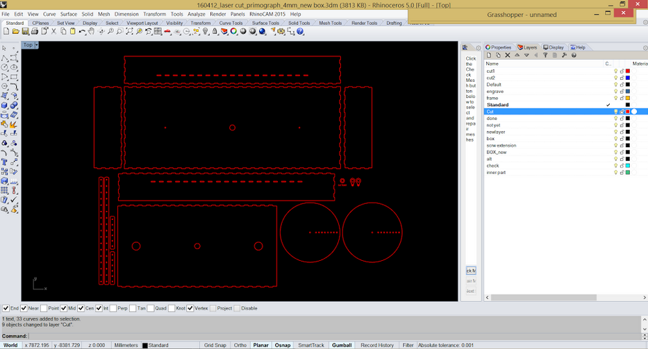
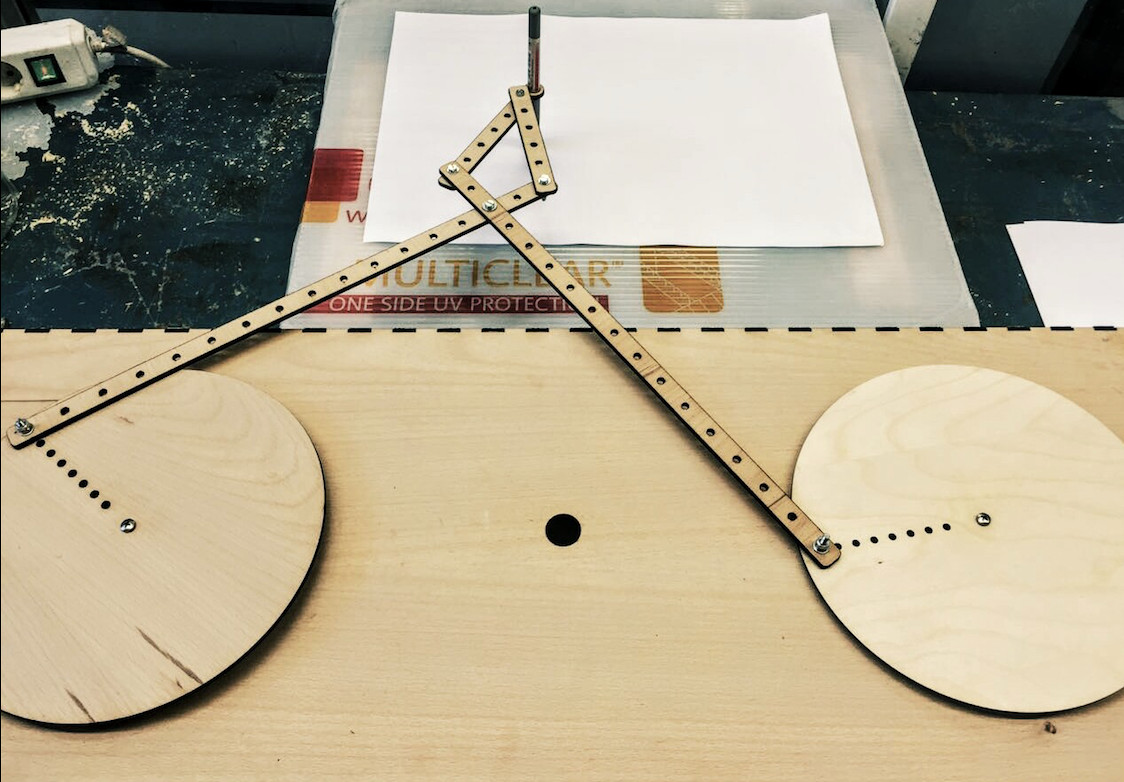
// Fourth test: MDF Wood on Multicam 2000 Laser
The cutting worked fine, however when we assembled the box, we realized that we had misplaced the gears, they were a bit wobbly, so we went back to the design file and relocated the gears. We laser cut the box again and reassembled it.
Laser Cut File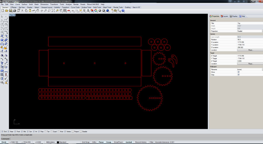 Multicam 2000 Laser Cutter
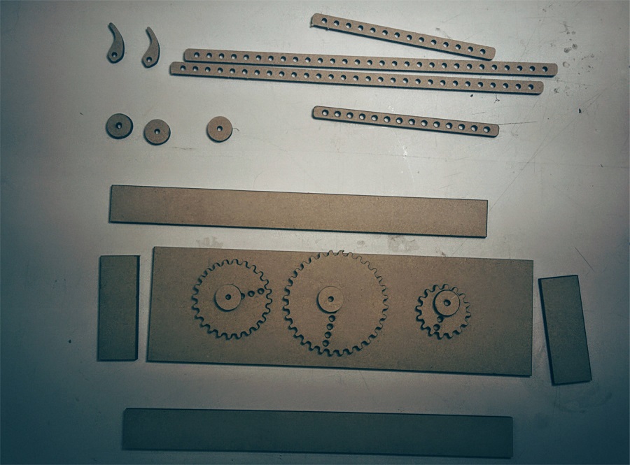
The prototype works, however, there is lots of room for improvement:
* The pen holder doesn't do its job (duct tape is a sign of failure!)
* A bit instable and wobbly (we need to locate the grip to move the mechanism differently.
* Improve gear mechanism to generate different more interesting patterns.
* Decision to be made wether we build a one motor or two motor mechanism: 2 motors with different speeds for different patterns/ 1 motor might not be powerful enough to move both gears.
First Prototype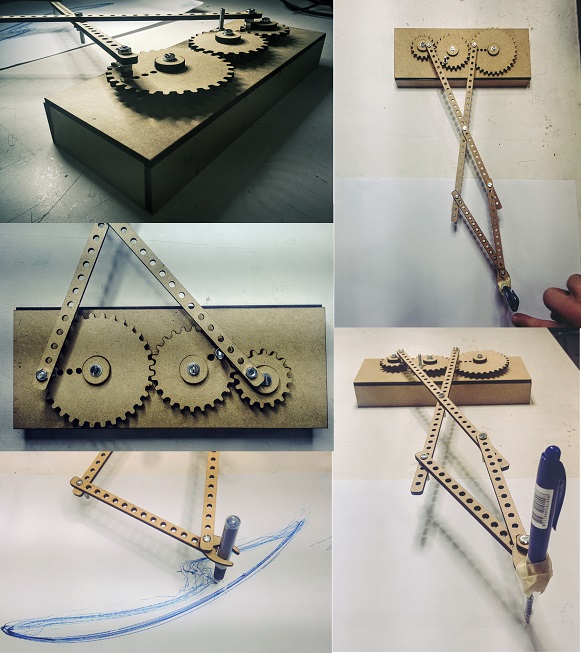
First Prototype Trial from Elissa Sophia Assaf on Vimeo.
During the second week, the machine design week, we brainstormed the design and functioning of the machine together and settled on a plan of action. Norma kept track of the work processes for our documentation and conceptualised further development of our automatic primograph. Eva and I did the 3D modeling in Rhino and Blender, and Norma contributed to more box outlines in Inkscape. Andreas was prepping the two motors and explained to us how to connect them with a Rasperry Pi and also to explained the python code to run them (Andreas gives workshops for kids so he is pretty patient when it comes to that). Together we did the laser cutting, 3D printing of parts and assembling of the machine.
Software: Python; Rhino and Grasshopper; Inkscape; Blender; Cura
Machines: Multicam 2000 Laser Cutter; 3D printer
Materials: MDF Wood/3mm; Filament
Other materials: screws, nuts, 2 DC motors, Raspberry Pi, button including a LED.
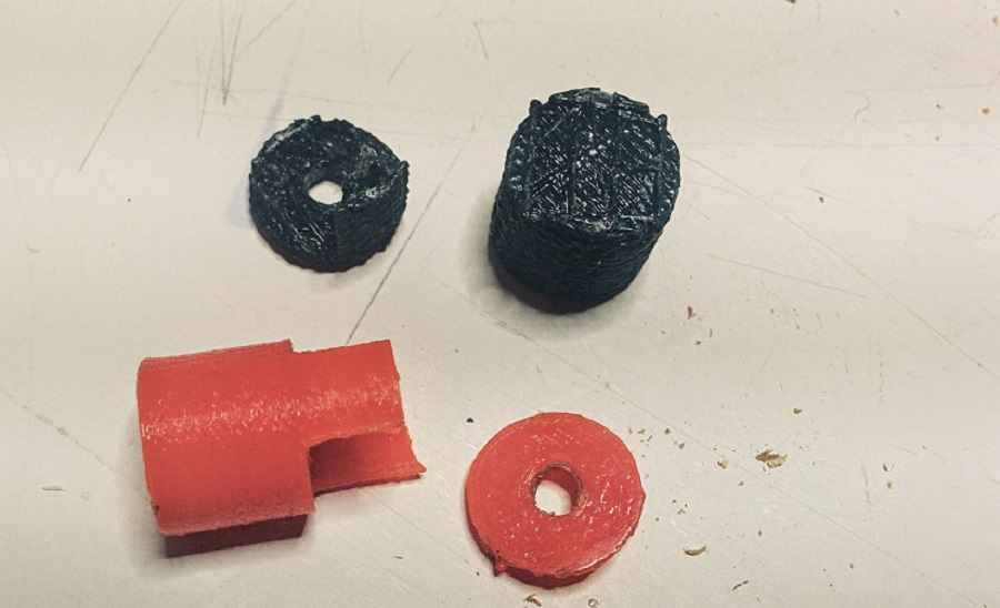
To improve the accuracy of our machine, we now have two detached gears, instead of three interconnected ones. We increased their size to 200mm in diameter. They are operated by two motors respectively, which increases the level of control. We can now change the speed of each gear independently. We decided to do this to create a certain drawing pattern, that we picked from Eva´s previous kinetic research at Angewandte University of Vienna and that we liked most. Additionally, we increased the length of the longer arms to 380mm each, and the shorter arms to 100mm each. The pen holder is now one piece only, with a polstering of foam. We further redesigned the size of the box container itself (800mm long - 300 mm wide - 150 mm high; material thickness 40 mm) to adjust to the new measurements of gears and arms. To include the motors and improve stability, the box has three layers: the top layer has the on/off button and holds the gears, which are screwed to it. The second layer stabilizes the gears. The third layer under it has the motors attached, screwed onto it. The gears are connected to the motor with a 3D printed "pipe" system, that contains long screws. Additional 7 screws hold the top parts mechanism together, another 8 screws hold the middle and bottom layer and fix the motors in place.
New Pattern Simulated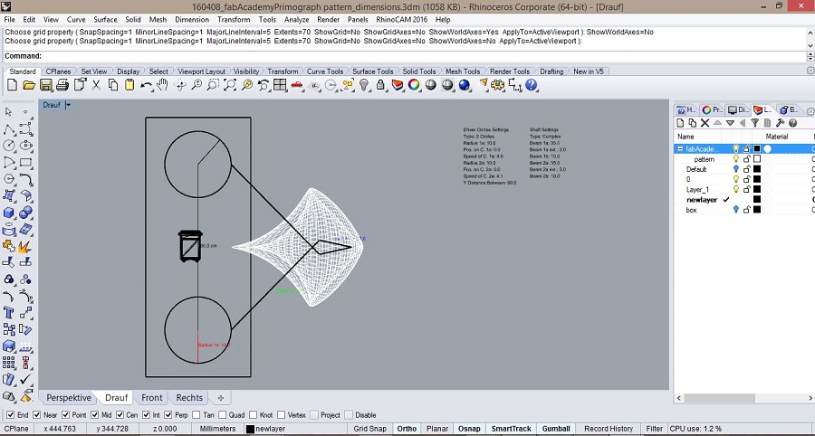 Box laser cut file
 Mechanism
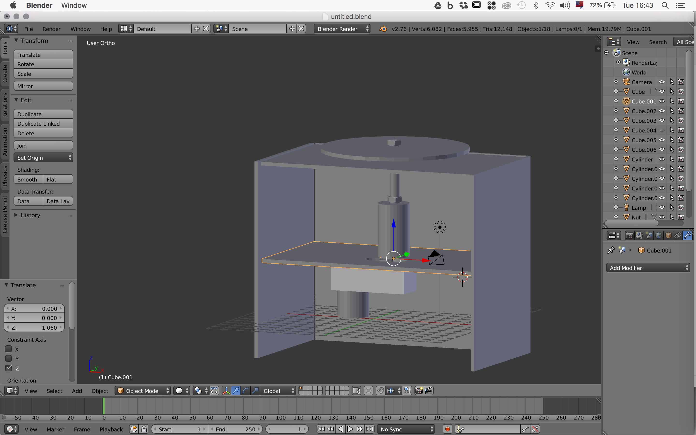 Part connecting the motors to the gears
 They were too thin so they broke because they couldn't handle the pressure weight and velocity of the motors
 Raspberry Pi Casing
.jpg)
.jpg)
* We were supposed to add another nut in the hole on the bottom part and tighten the 2 nuts to fix the gear part to the motor but the screw wouldn't fit in the hole of the 3D printed part so we had to redign and print it.
* Design and Materials: Our design was based on MDF Wood with 4 mm thickness, but we ran out and had to redesign the Rhino files for laser cutting to get proper dimensions of 3mm material thickness instead.
* Laser Cutting: Didn't cut through everywhere, because the board was bent. So we had to cut some pieces twice. However, now the screwholes on the arms were a little bit too big, which would result in a wobbly arm mechanism. So we cut the arms again.
* Design and 3D Printing: 3D printed parts broke in the assmebling process, its top sides were too thin to withhold pressure.
Second Prototype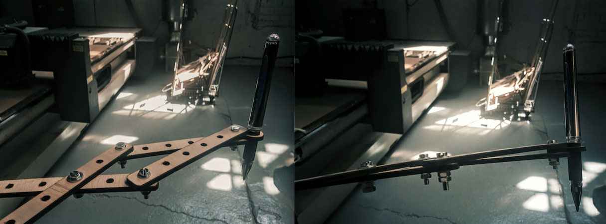
We discussed the design of the mechanism together. Andreas took charge of the electronics. He connected the two stepper motors with four cables to on/off button and the Rasberry Pie. He extended the cables and modified the button, so it includes a led to display on/off mode based on a previously designed app to controll the motor, he programs the Raspberry Pi with Pyhon, explaining every step to the group. He further explores how to incorporate a slider in the app to control the speed of the stepper motor (pulse width modulation). I was mainly busy with the design of the laser cut files of the box with its layers, the beams and the pen holder, working in Rhino. Norma aslo made a box with finger joints in Inkscape to be test. Eva and I designed the Blender model of the "pipe" system that connects the gears to the motor. Norma took the measurments of the motor and passed them to generate this model. Eva and I also took charge of the 3Dprinting of the parts we had designed on rhino, as well as the holder for the Raspberry Pi (designed by Andreas previously), the connecting "pipe" system as well the part I had designed for the pen holderafter exporting the .stl design file into the 3D printing cura software to generate the Gcode. Norma moved between group members, discussing upcoming problems and updating everybody on everybody elses´ progress, while collecting and sorting work and documenation files. She also shared the .HTML documentation, so everybody could have the outline of the process, to later modify seperately.
The idea is to let the primograph draw something specific. A friend of Norma has generated a code with Python that visualizes the density of Twitter usage in Barcelona. The digital visualisation of the regional Twitter activity is simple, displaying the areas of usage as different-sized "bubbles" according to the amount of connections. Instead of a digital visualization, it would be interesting to let the primograph physically draw the density of twitter usage in BCN on a map of the city. Each "bubble" would be drawn in the set pattern, however differing in size due to different speed settings corresponding to Twitter usage intensity. It would be even more interesting, if the Machine could move from "Bubble"(= place) to bubble to draw the twitter usage intensity automatically in real time. We liked the translation between the digital and the physical in this idea as well as the playing with representations of geography and maps.
To automate our primograph, we decided to use a Raspberry Pi and a motor controller board, and Andreas made a schematic in Fritzing.
Bill of Materials
Raspberry Pi 3
* Explorer Hat Pro
* 2 X DC Motors
Push Button with LED
*Software to burn the raspberry pi image (PiBaker)
The idea is to hit the arcade button in the middle of our Primograph to be able to change the speed of the motors exponentially.
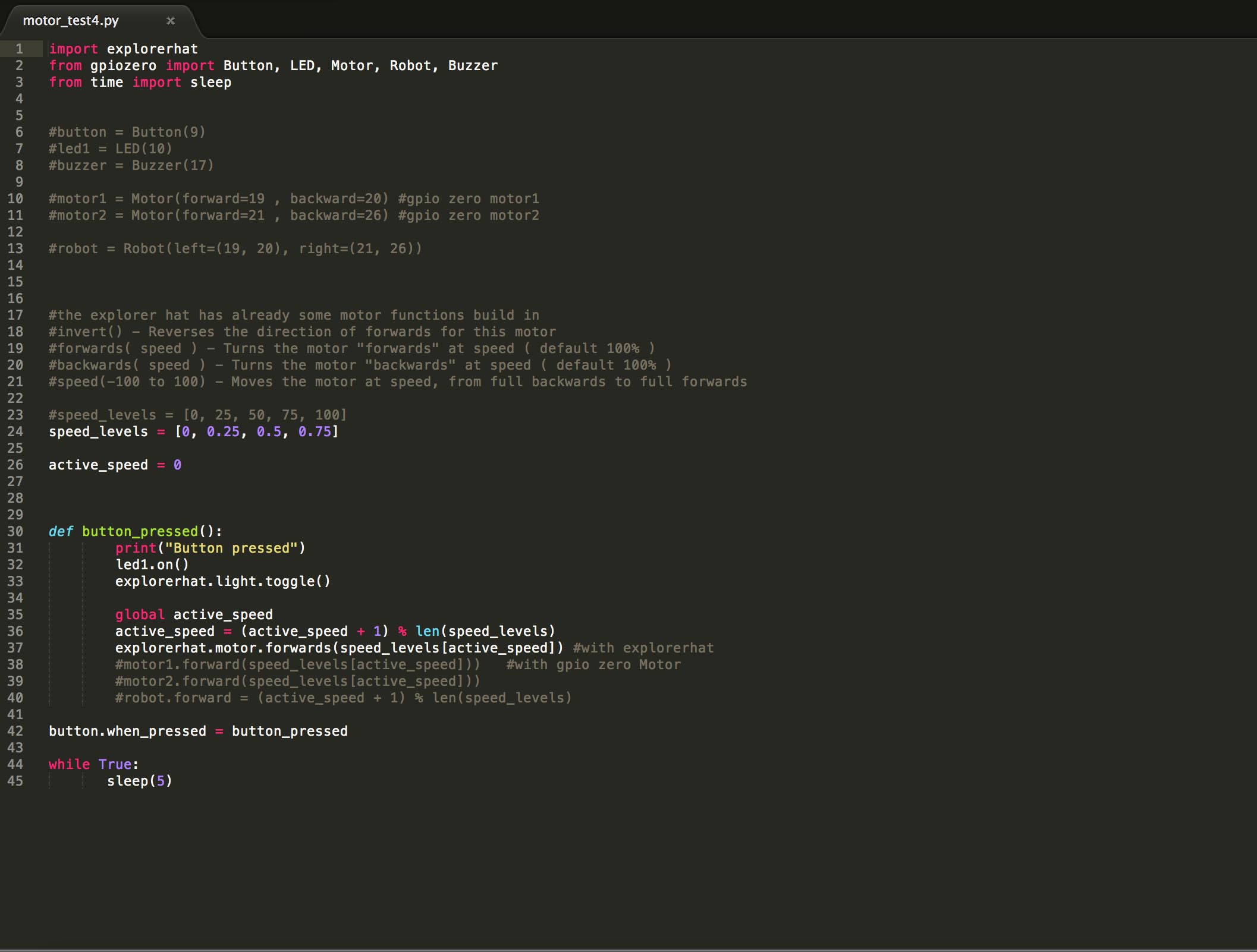
The Explorer HAT uses an output driver chip called the ULN2003A, which contains a set of transistor pairs called a Darlington Array. It transforms the small logic signal of the Pi into something capable of driving much bigger loads, such as motors, steppers, lights and more.
After a couple of hours wondering why the output wasn't working Andreas found this:
The 4 outputs on Explorer can sink 5V, but not source. This means you need to connect your load to one of the 5V pins, and then to the output. When you turn the output on it will connect your circuit to ground, allowing current to flow and your load to turn on. This is the opposite of using a bare Pi GPIO pin, where you might connect to the pin and then to ground.
In the meantime, Andreas had already connected the Button and the Led of the Button to MISO and MOSI pins.
He also looked at the Data Sheet of the Motor Driver which is a Dual H-Bridge Current Control Dribver DRV8833PWP and realized that he could not only control DC Motors but also Stepper Motors and is also able to control the speed with PWM which is the technique by which you control the speed by turning the motors on an off very fast.
These are the commands for the Motor we can use:
invert() - Reverses the direction of forwards for this motor forwards( speed ) - Turns the motor "forwards" at speed ( default 100% ) backwards( speed ) - Turns the motor "backwards" at speed ( default 100% ) speed(-100 to 100) - Moves the motor at speed, from full backwards to full forwards
Make everything boot at startup after making the raspberry pi battery=powered.
To set up the Explorer Hat, Here is the function Elissa Sophia Assaf on refecence.
First test automating the Primograph using Python to program the servo motors from Elissa Sophia Assaf on Vimeo.
Electronics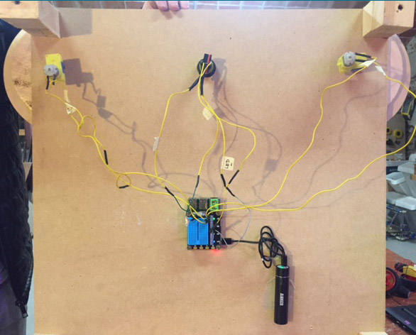 Final Pattern
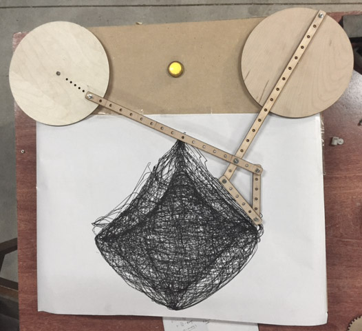
Primograph Automated Machine from Elissa Sophia Assaf on Vimeo.
You can download all the .stl .3dm .py files here.
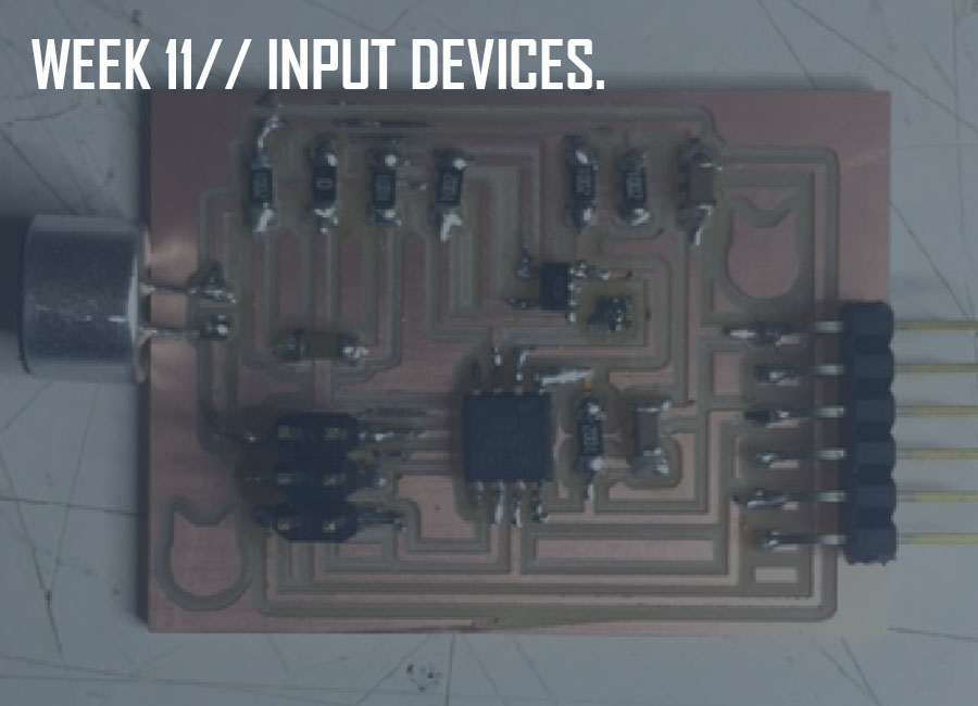
This week's assignment was to measure something by adding a sensor to a microcontroller board and reading it.
We kicked off the week with an introduction to the Input Devices available, with Neil Gershenfeld.
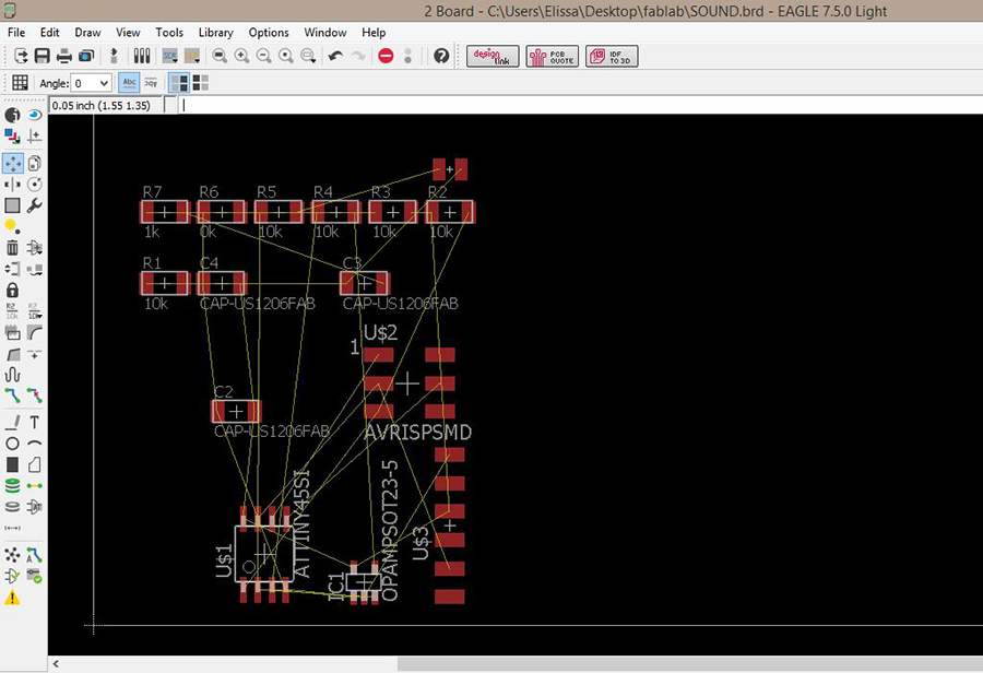
Since my final project consists in translating sound data into light, I decided to redesign the sound board from Neil.
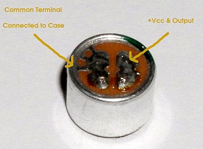
The first step was to redign the sound board using the electret microphone (since the mems wasn't available at the lab), an OP amplifier and the ATtiny 45 microcontroller after reading the datasheet.
I used the Eagle software to redesign the board following Neil's board.
Here's the list of components used to build this circuit:
ATtiny 45
6-pin Programming Head
6-pin FTDI Header
Electret Microphone
Op-Amp
Five 10k Resistors
One 1k Resistor
One 0k Resistor used as a jumper
Three 1uF Capacitors
Hello Mic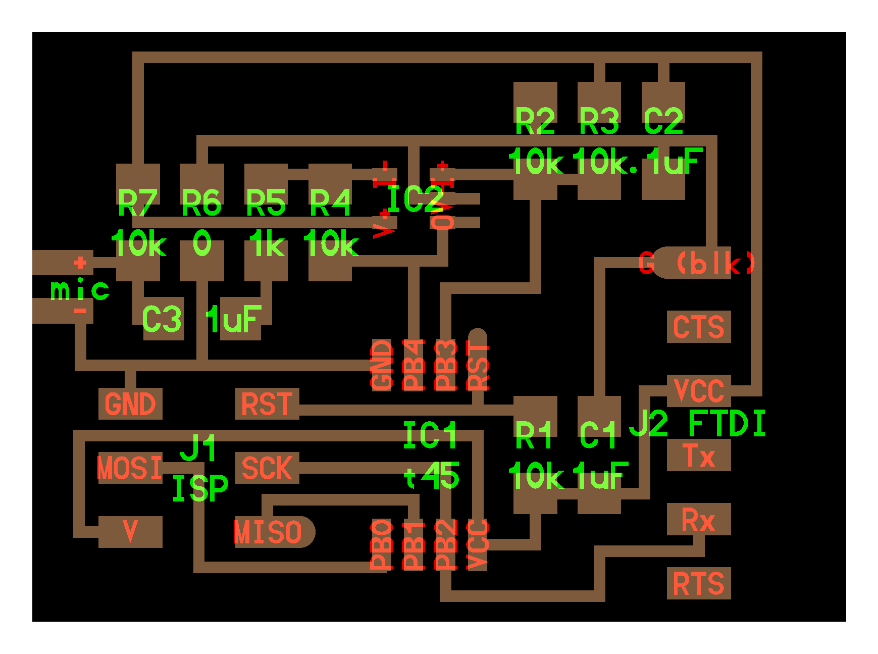
 Schematics
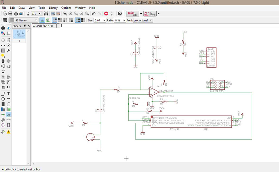 Board
Board
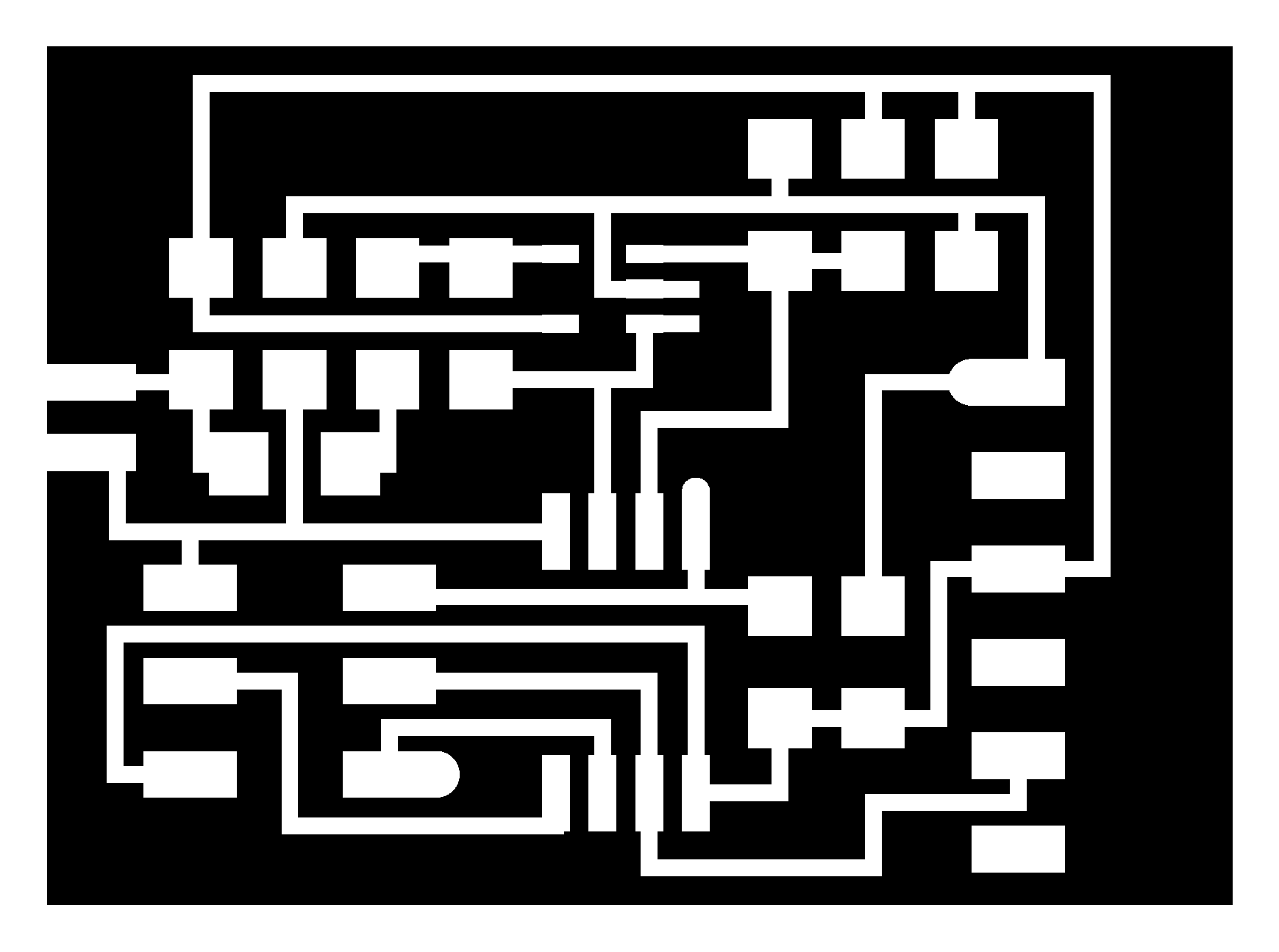
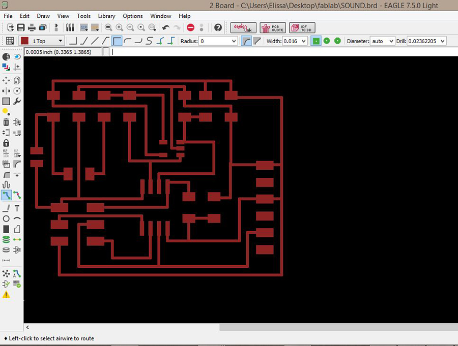 Traces
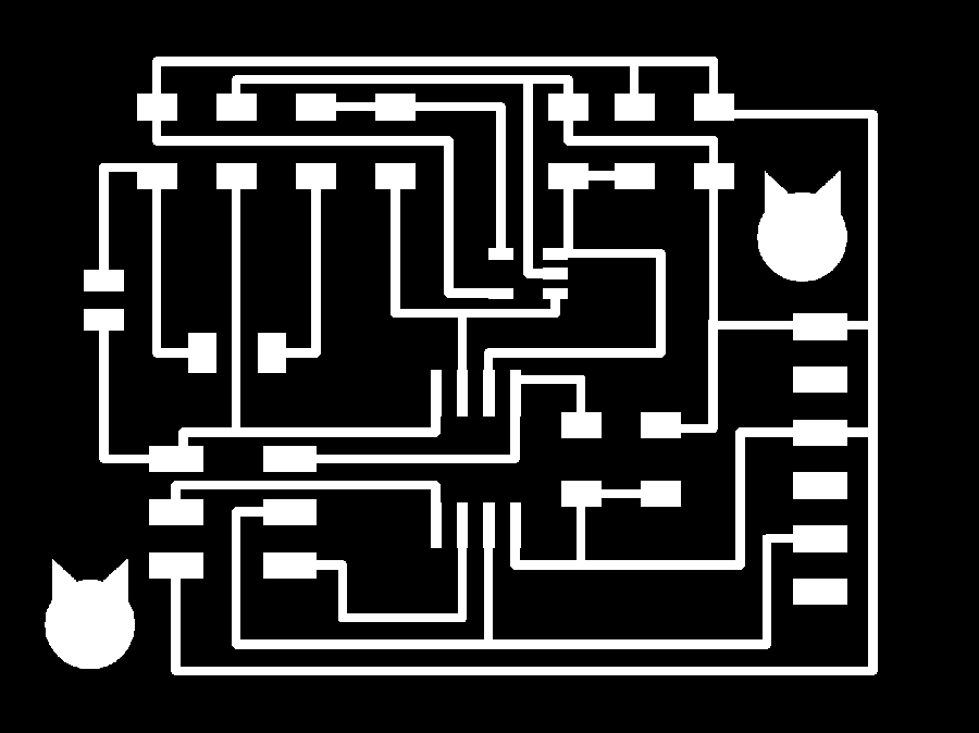 Outline

You can download the Eagle schematics and board here.
As seen in the previous weeks of electronics production and electronics design (4 and 6), we used the Fab Modules and the Roland mill machine to mill the board.
I had some hard time milling the traces (board was bent/mill was fixed too low...), and had to mill it over again four times.
Fail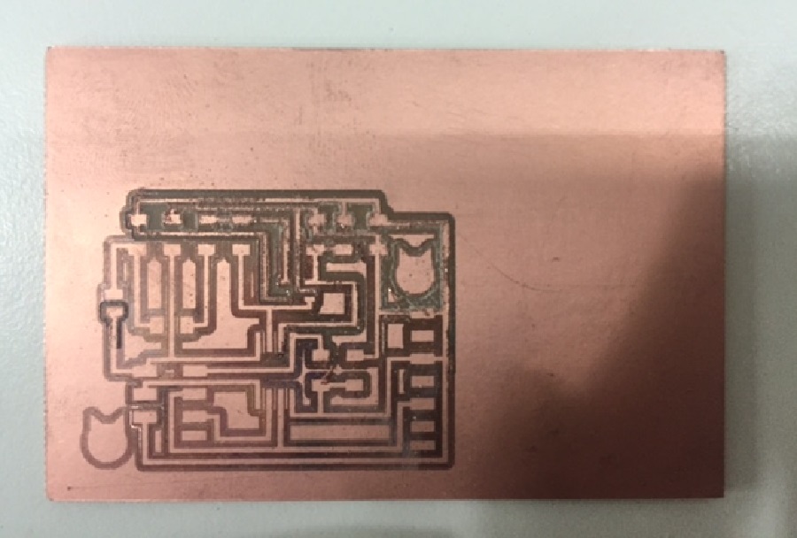 Fail
Fail
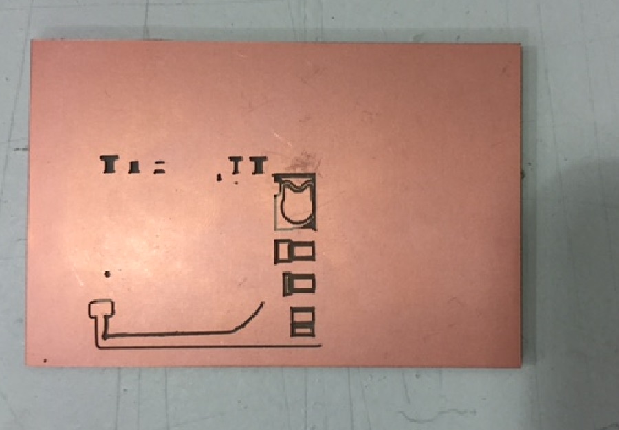 Success
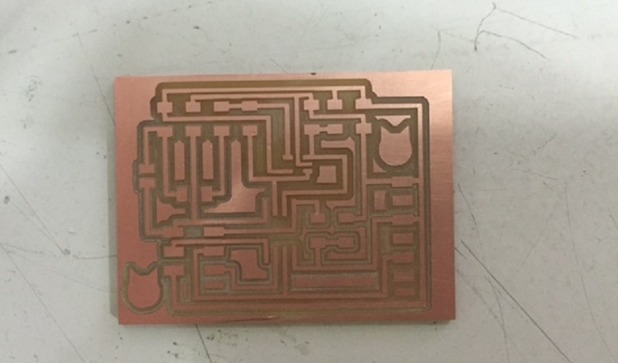
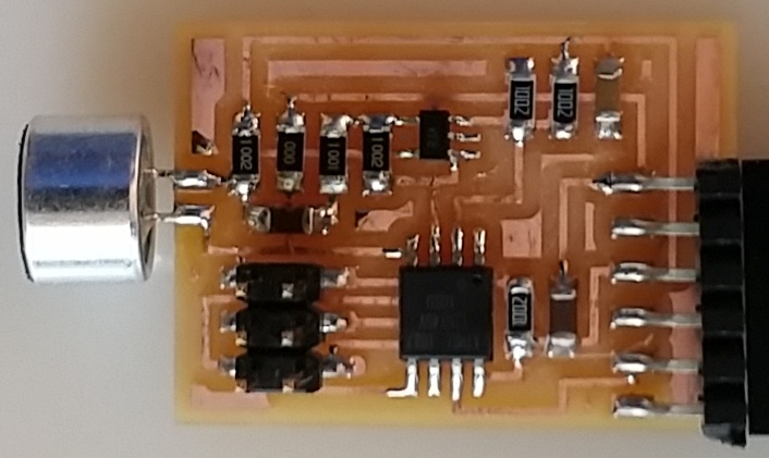
It is important when soldering to mind the polarity of the electret microphone.
 Stuffed Board
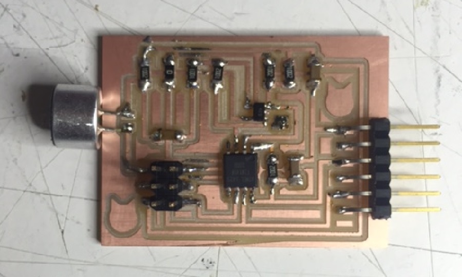
I rebooted the pc using the pin with lubuntu Ferdi had provided for us (miserable windows 8 users), to be able to program the board.
I first connected the board to the fabISP and to the computer using the FTDI cable and the usb cable to provide power.
I then downloaded these files into the same folder:
href="http://academy.cba.mit.edu/classes/input_devices/mic/hello.mic.45.make">Make fileBut it seemed I had shorts in my circuit because it wouldn't read my board.
!Always make sure you don't have short circuits in your board before connecting it orelse you might burn your computer!
I went back to the board file on Eagle and found out my GND was connected to my VCC through the 6-pin FTDI header (which made sense because the multimeter was beeping when connecting the two ends of my capacitors), and disconnected them manually using a cutter to scratch off the copper.
ERROR ERROR ERROR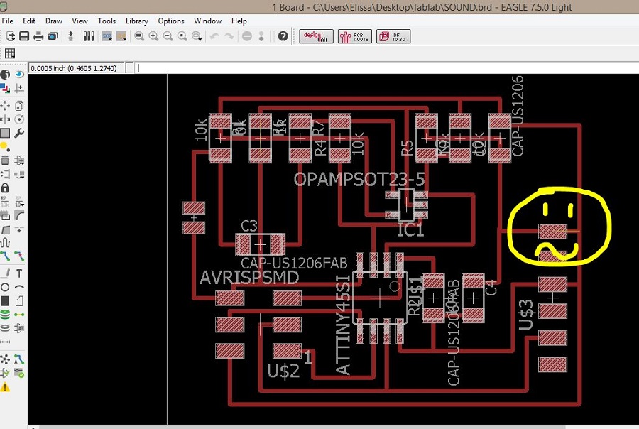
Since my computer was somehow running very slow with lubuntu, I used Santi's mac to proceed with the programming.
In the terminal, type in:
cd the directory where these files are
make -f hello.mic.45.make
make -f hello.mic.45.make program-usbtiny
Type in ls /dev/tty.usb* to find the serial port you are using. Mine was FT94SBVB.
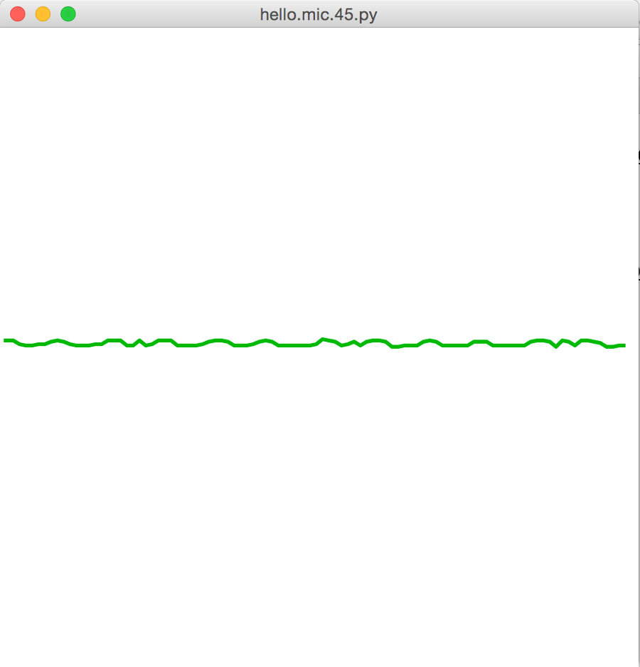
To run the python program type in: python hello.mic.45.py /dev/tty.usbserial-FT94SBVB to visualize your board measuring the sound.
You can now remove the usb cable and keep only the FTDI cable connected to your computer.
 The microphone was actually in the cavity of my mouth when I screamed and this is how it reacted -_-
It probably has to do with the programming of the amplifier which I will be working on in the coming weeks
Hello? Is anybody there?
The microphone was actually in the cavity of my mouth when I screamed and this is how it reacted -_-
It probably has to do with the programming of the amplifier which I will be working on in the coming weeks
Hello? Is anybody there?
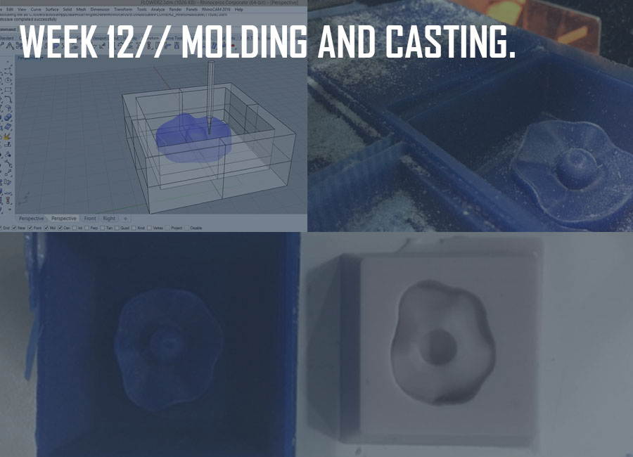
This week's assignment was to design a mold and machine it.
We kicked off the week with an introduction to Molding and Casting techniques, materials, and tips.
The steps to molding and casting, are designing a 3D model, milling the part out of a box (wax box in our case) for making a positive mold, creating a silicone negative, and finally filling in the silicone mold with the appropriate casting material.
A few things to keep in mind when modeling a mold:
//Keep a minimum thickness above the highest model point for the negative mold to be think enough
//Designing around the tool that is used to mill
//Creating inclinations on the inside edges and the model
//Maintaining a margin between the model and the edges bigger than the diameter of the mill that is used
//If designing a two-sided mold, create fixing points, and two holes exposed to the outsideone to pour liquid and the other to ventilate(to avoid having entrapped air/bubbles).
In my case, I was creating a one-sided mold, out of the part that I had scanned during the 3D printing week, and since I had perpendicular facets, deeper than the 1/32 bit length (3mm), I decided to mill using the bigger tool, the 3mm square mill,to be able to keep the outline and the size rather than the high resolution which was not very necessary.
A good trick is to draw the 1/32 mill or 1/64 mill depending on which one you plan on using, to see which part of your model needs to be modified to avoid breaking the mill.
Designing the Model on Rhino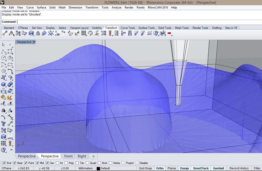
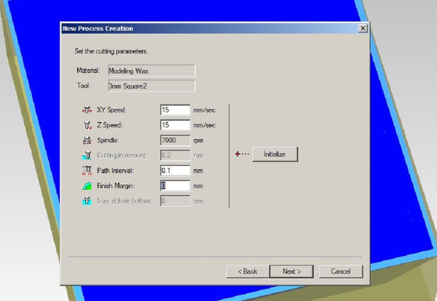
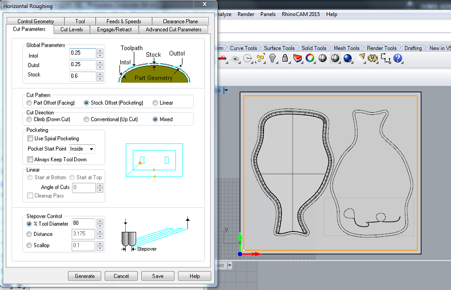
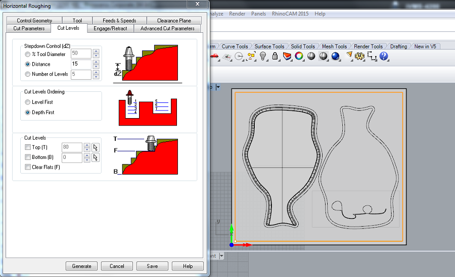
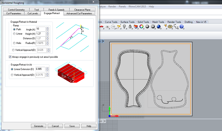
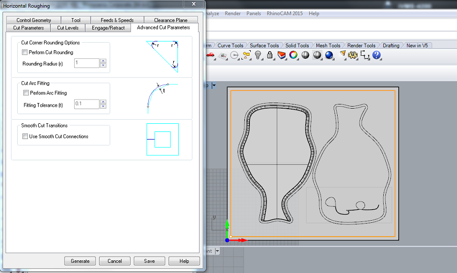
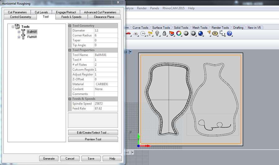
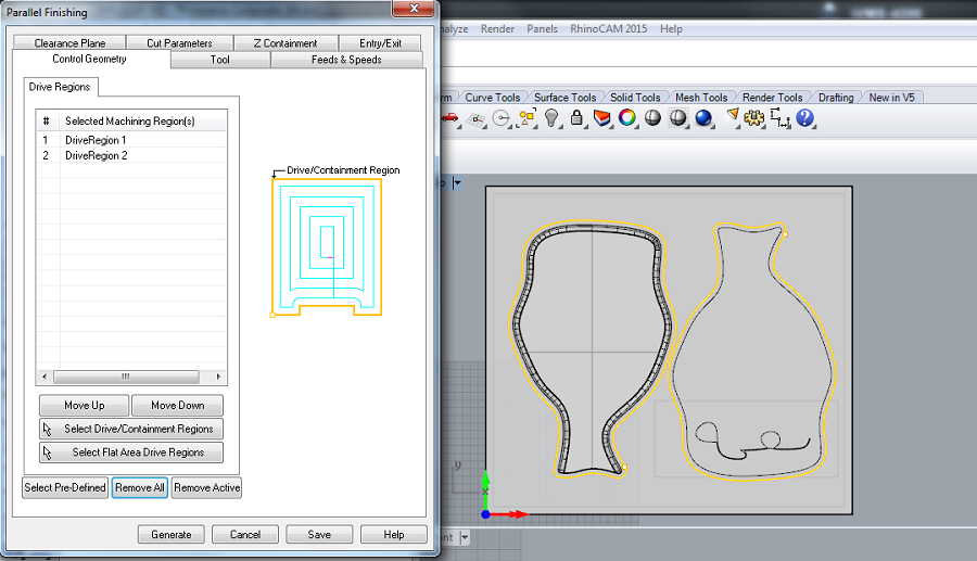
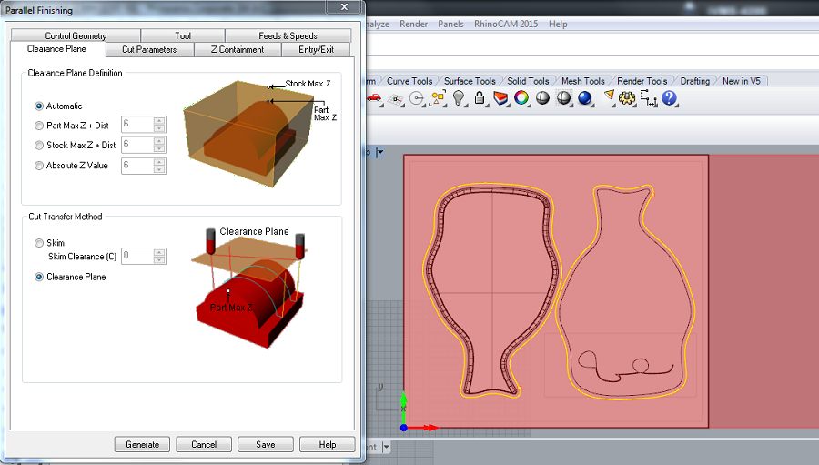
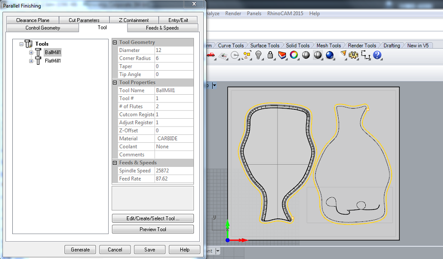
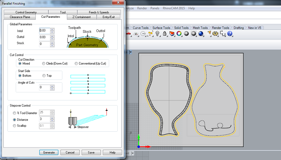
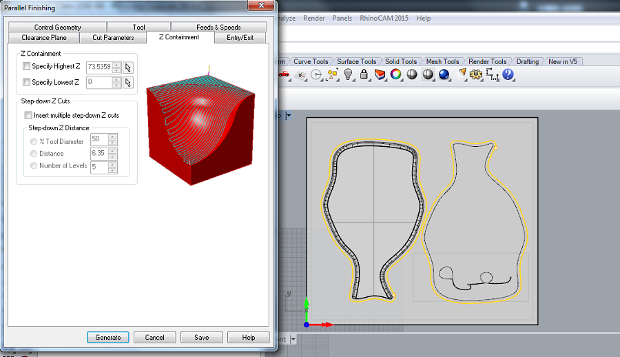
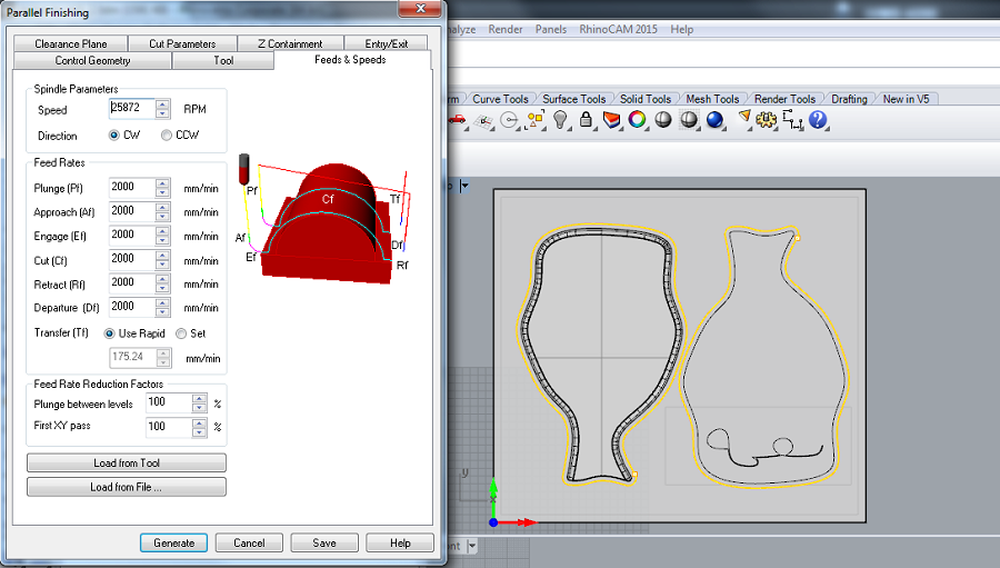
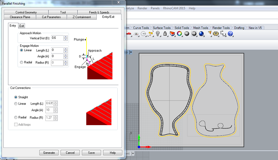
In my case, the roughing and the finishing were done on the Roland milling machine using the Modela Player 4 software, with the same 1/8 mill, and the different parameters below.
Rough Cut Parameters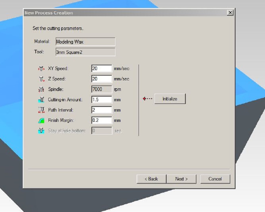 Finishing Cut Parameters
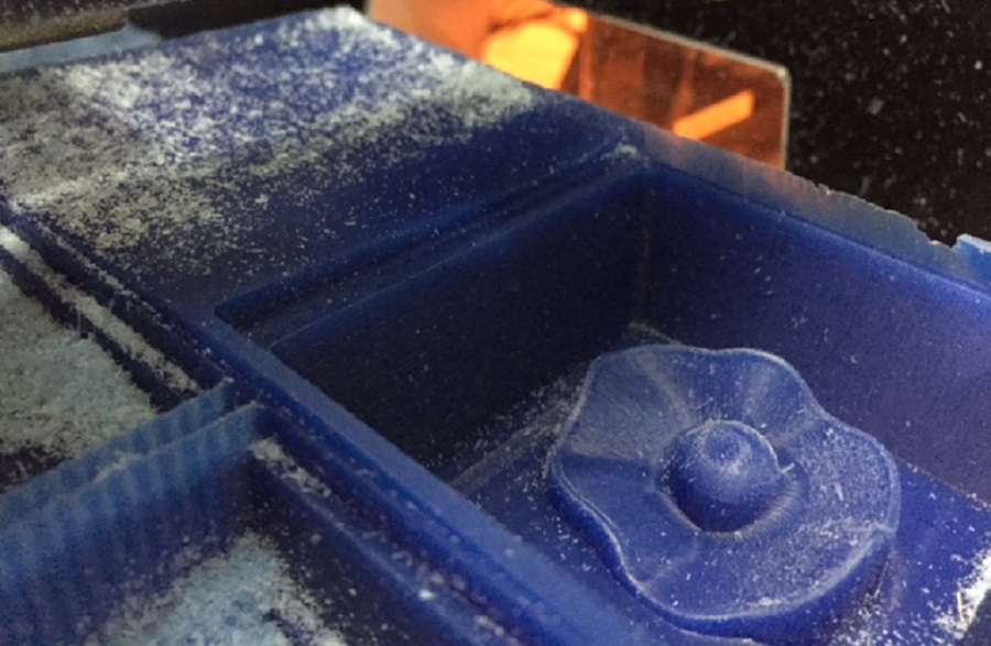
 Milled Mold
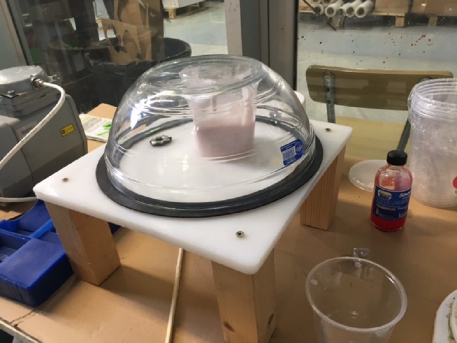
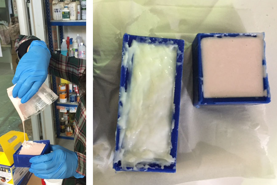
Make sure you pick the appropriate casting materials for the negative mold depending on what you want to cast as a final result. In my case, I used food-safe material with silicone.
I started by filling the mold with water to weigh the volume to be able to proceed with the mix.
I then poured 90g of the platinum cure silicone rubber and 9g of silicone rubber compound (ratio of 10%) and stirred until I got a completely homogeneous mix.
With the help of Ferdi, I then used the vacuum to degas and eliminate entrapped air, and finally poured it into the mold.
Food-safe/Silicone Casting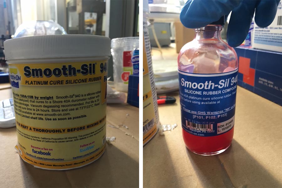 Vacuum Degassing
You can download the mold .stl file here
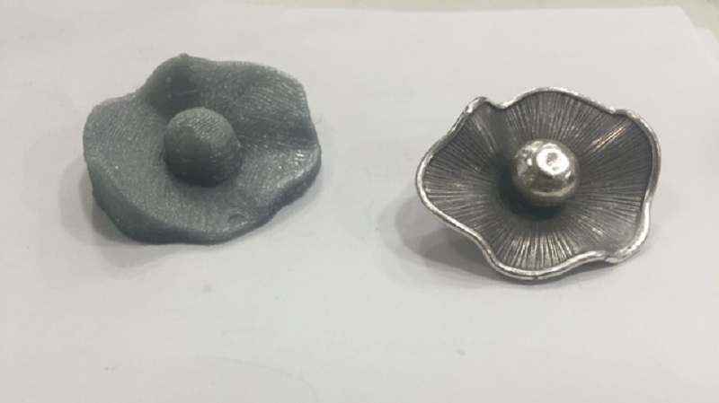
The result for the negative mold was satisfying, 24h later.
Negative Mold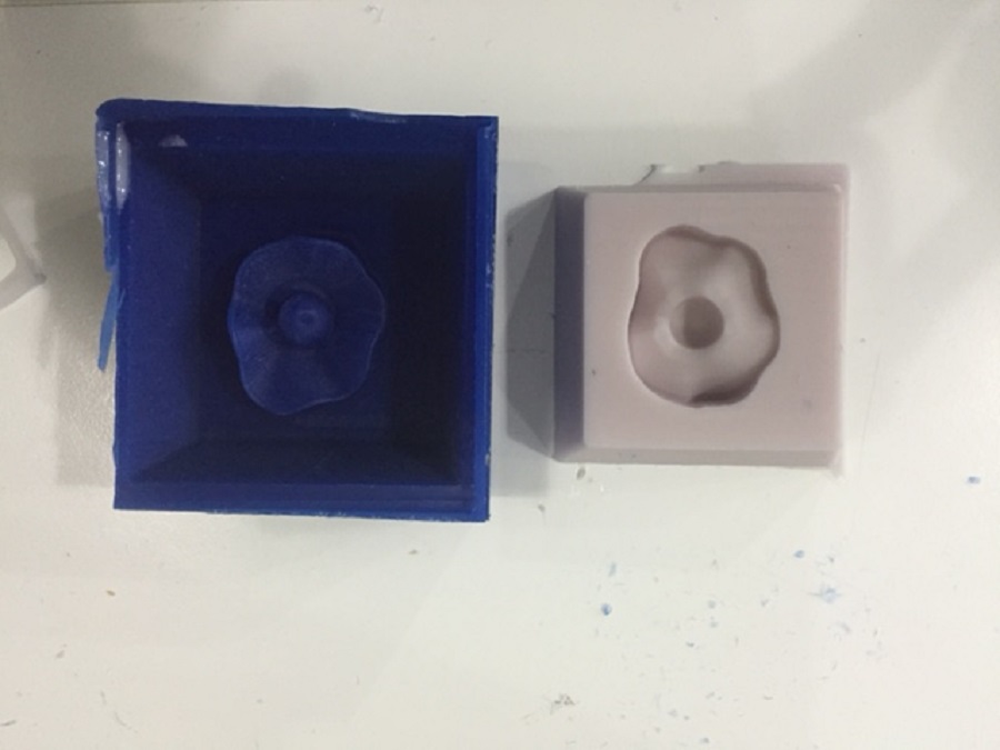
For the final casting, if casting chocolate, follow these saftey instructions for food related applications.
However, I'd like to cast some metal or silver eventually with the help of Ferdi.
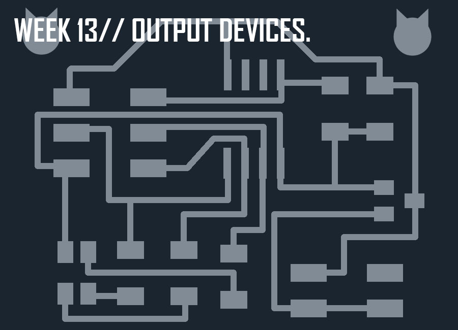
This week's assignment was to add an output device to a microcontroller board and program it to do something.
We kicked off the week with an introduction to the possibleOutput Devices to explore, with Neil Gershenfeld.
Since my final project consists in translating sound data into light, I decided to redesign the RGB led board from Neil.
The first step was to redign the RGB led board using the RGB led available at the lab, and the ATtiny 45 microcontroller after reading the datasheet.
I used the Eagle software to redesign the board following Neil's board.
Here's the list of components used to build this circuit:
ATtiny 45
6-pin Programming Head
4-pin Header
RGB led
Voltage Regulator
One 10k Resistor
Two 1k Resistors
One 499k Ohm Resistor
One 1uF Capacitor
Hello RGB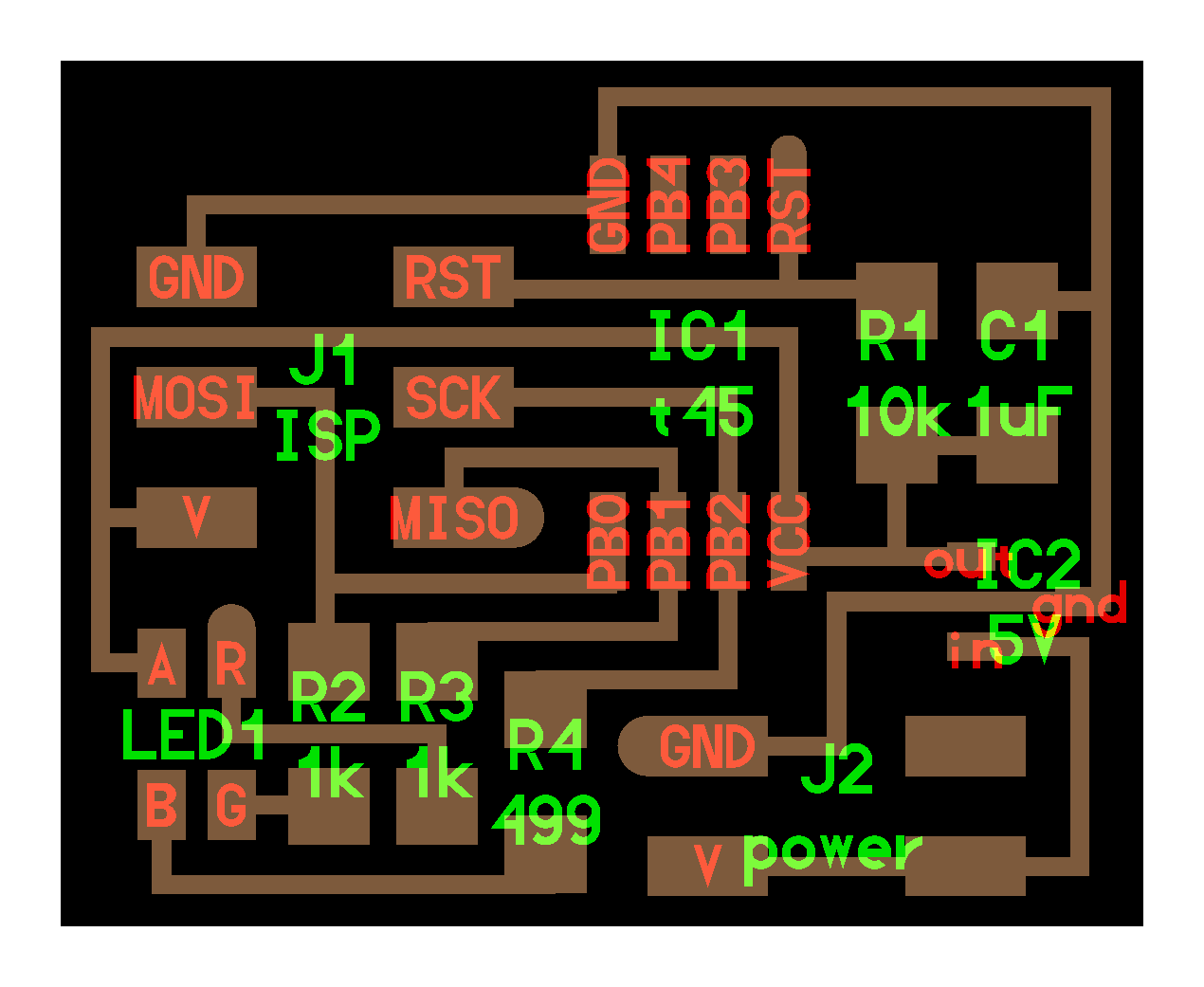
Making the schematics was a bit tricky since all the previous years had used the ATtiny 44 microcontroller as opposed to the ATtiny 45 this year, so there wasn't really any point of reference for the schematics which helped me learn even more.
Schematics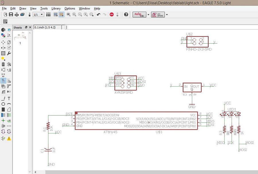 Board
Board
 Traces
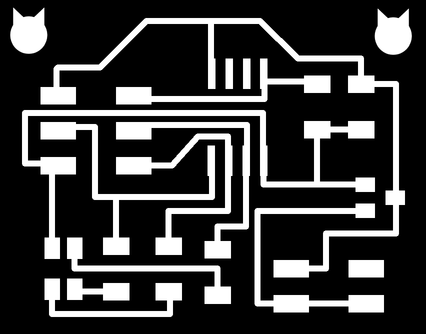 Outline

You can download the Eagle schematics and board here.
As seen in the previous weeks of electronics production and electronics design (4 and 6), we used the Fab Modules and the Roland mill machine to mill the board.
Milled Board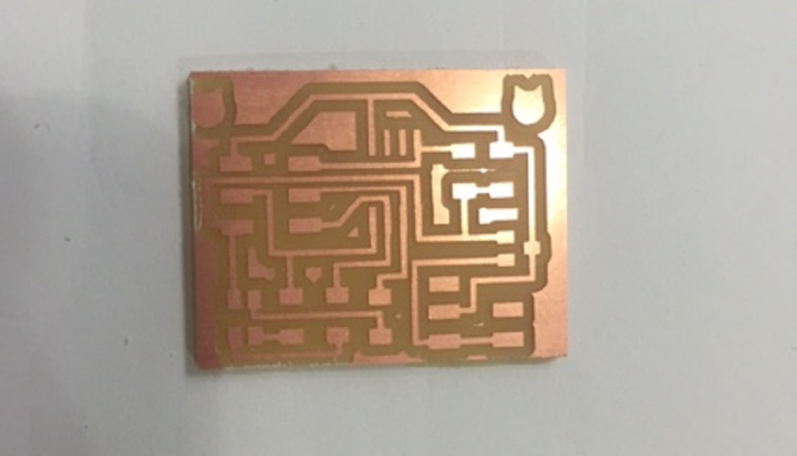 BOM
BOM

It is important when soldering to mind the polarity of the RGB led.
Stuffed Board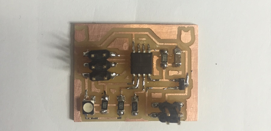
Before soldering connect the board to a 5V battery through the 4 pin header with positive pin to V and the negative pin to GND, and use a multimeter to troubleshoot the board and make sure a 5V current is running.
To program the board, I connected the board to the fabISP and since I have an external power supplier connected to the board I didn't use an FTDI to source power.
I then downloaded these files into the same folder:
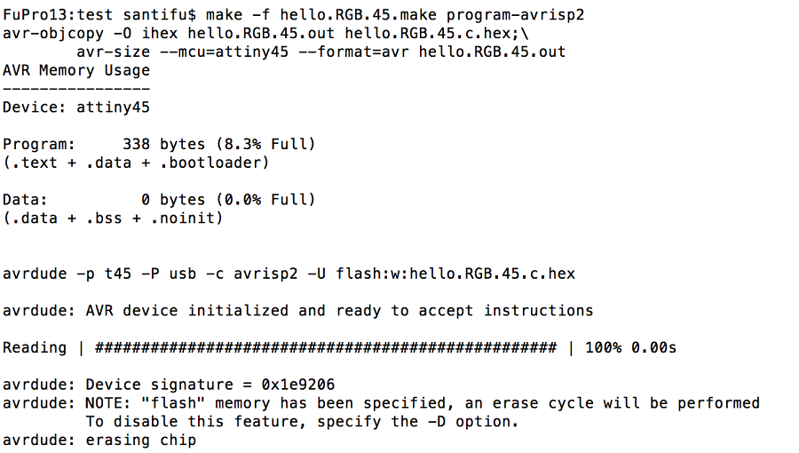
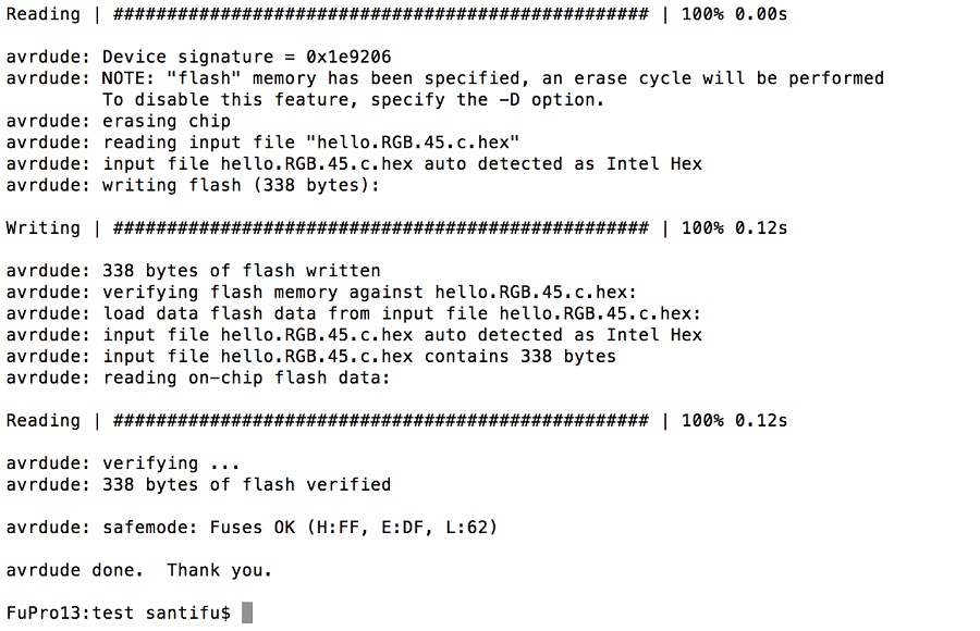
In the terminal, type in:
cd the directory where these files are
make -f hello.RGB.45.make
make -f hello.RGB.45.make program-usbtiny
Since I was getting an error, and that I wasn't using the battery I first used, I figured that the problem was that it wasn't generating power to the board, because the first battery I had used made the led light in one color meaning there was a power current enough to light it.
I had also connected it to the avrisp just to make sure the problem wasn't from the fabISP, but it wasn't because the computer could read it.
Once I had replaced it, I was able to program the board without any errors and then disconnected it from the fabISP, keeping only the battery to supply it with power.
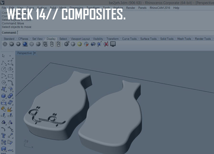
This week's assignment was to design and make a 3D mold, 3D mill it using a CNC milling machine and produce a fiber composite part in it.
We started off the week with an introduction to differentcomposites materials, processes, and ways of molding.
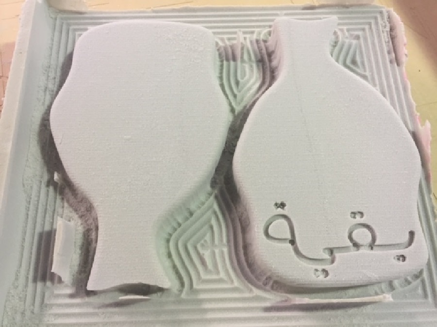
The first step was to design the mold using a 3D modeling sofatware and since we were using burlap as a textile, I decided to make a purse, inspired by the بقجة (which has no specific translation), which was used as a bag to transport one's belongings in the past.
Designing the Model on Rhino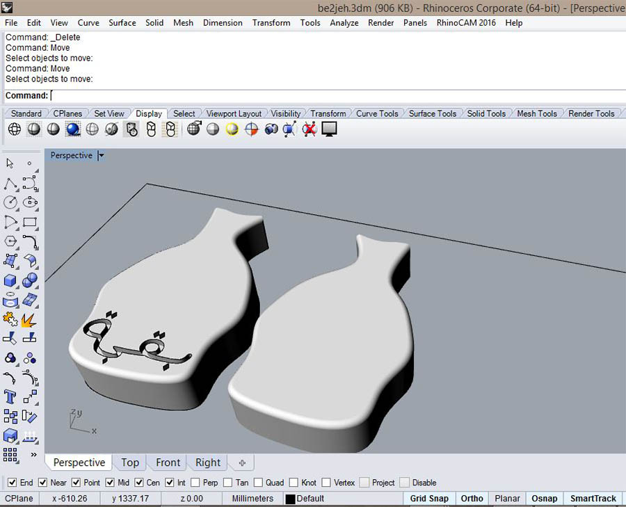

 Finishing Cut
 foam mold
3D milling a foam mold using mars3 CNC machine from Elissa Sophia Assaf on Vimeo.
"Wet lay-up is a molding process that combines layers of reinforced fiber with liquid resin to create a high quality laminate. This process involves the positioning of reinforcement material into or against a mold in layers (in my case against). These layers are then impregnated with a liquid resin system, either with a brush and roller, to ensure a good wet-out of the reinforcement material. The step is repeated until reinforcement thickness is achieved. Curing can be performed at room temperature or under heat, depending on the selection of the resin system. This can be accomplished with the use of a vacuum bagging process."
Layering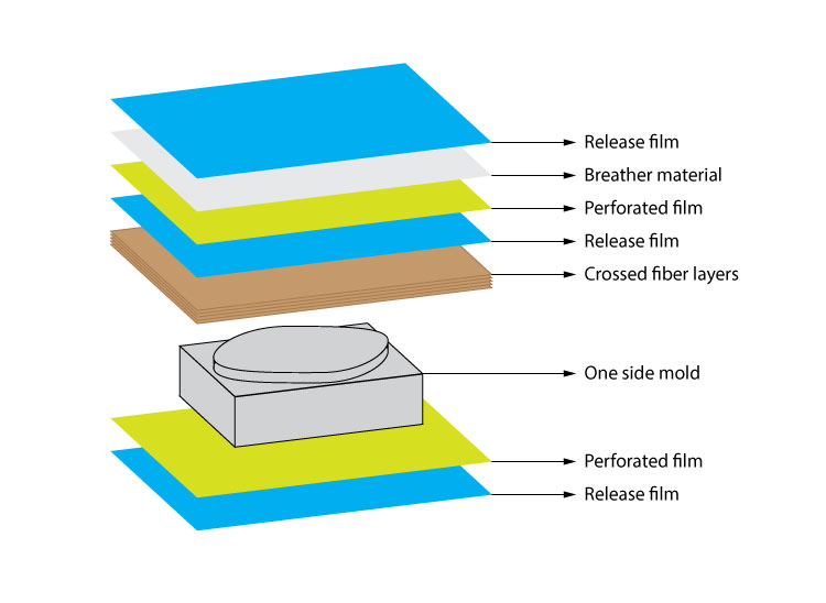
From bottom to top:
-Peel ply
-Perforated film
-Bleeder
-Seperation
-Breather
-Bag film
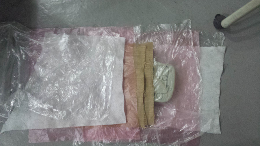
Preparing the mix/Epoxy Resin+Hardener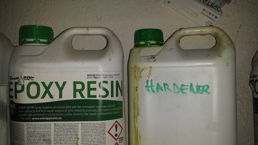
As for the mix, it should be done with a ratio of 2/1, with 2 times amount of Epoxy resin
It is very important to protect the skin, so gloves are mandatory!
After mixing the two products until homogeneous, the process should be done very quick (before the mix heats up and dries), and spread equally on the pieces of burlap (3 layers of burlap in my case).
The next step is the vacuum bagging process, and it is very important to cover the mold and all the other layers with two sheets of intact film (make sure they are not perforated), one on bottom and the other on top so as to protect the machine from the resin.
A satisfying result should appear twelve hours later.
Vacuum Process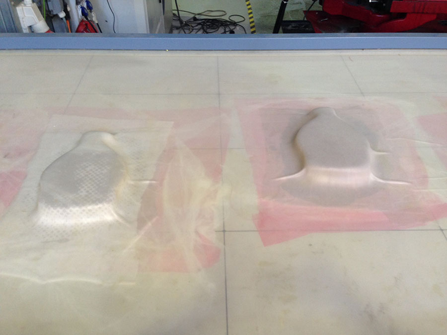 12 hours later
Since the carving was very thin, there wasn't enough room to absorb or suck the composites, but my plan was just to have an outline and to paint the word over it anyway so it was just a detail that wasn't very important for the design.
Another solution would have been to laser-cut a thinner outline of the word and to press it down so it would be better defined when undergoing the vacuum process.
For a smoother and better quality result, I should sand the two parts so they would better match.
The next step is to cover the inner parts with textile, add a zipper following the inner outline and a rope to the top part of the model so as to have the final purse design.
You can download the composites 3D model and gcode files here.
Also refer to my final project link to see the other composites I made.
This week's assignment was to design and build a wired and/or wireless network connecting at least two processors.
We kicked off the week with an introduction to Networking and Communications with Neil Gershenfeld.
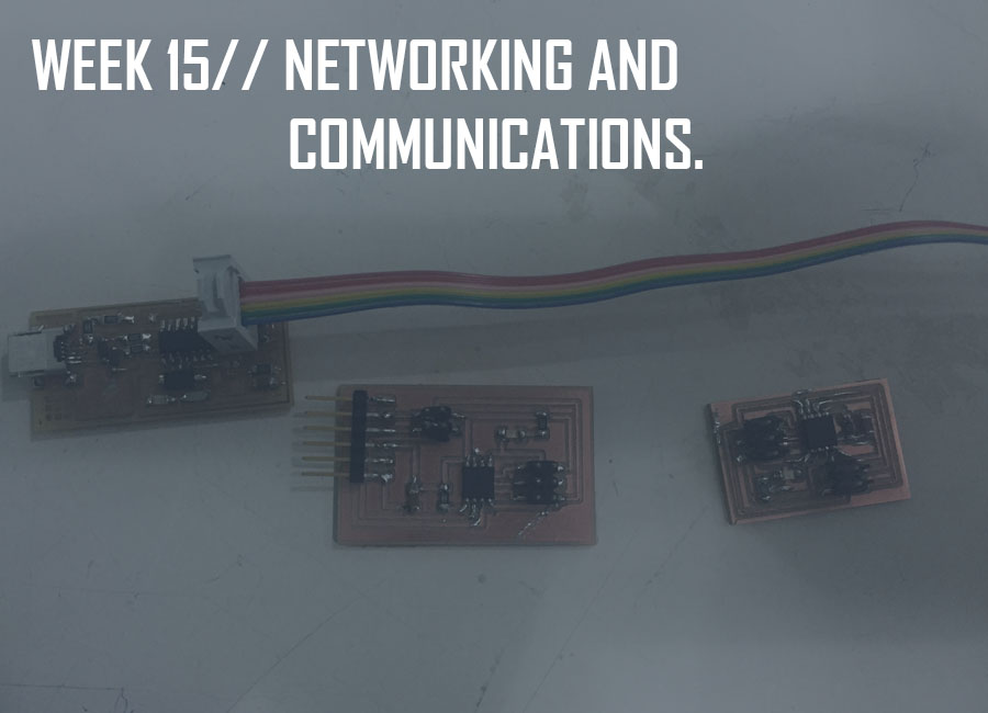
I decided to go for the serial bus example from Neil, and downloaded the files for the bridge board and the nodes board. The bridge board is also a node but holds an FTDI header connection in addition, to communicate with the computer. The communication between the nodes then works via serial Tx / Rx protocol.
The 3x2 headers in the two nodes boards connect with four cables only (Tx, Rx, Vcc, Gnd) and serve as serial communication between the nodes.
I used the Eagle software to redesign the boards following Neil's design.
Here's the list of components used to build the circuits:
ATtiny 45
6-pin Programming Header
4-pin Header
LED
One 10k Resistor
One 1k Resistor
One 1uF Capacitor
6-pin FTDI for the bridge board only
Stuffed Boards
I then downloaded the c code file and the make file, and created a folder for each node and the bridge.
Each node and the bridge are programmed individually so I opened the c file and modified the c code for the different boards.
Therefore each node has a different ID number and the bridge here is a node too: hence in the code, I modified the line #define node-id '0' for the bridge and #define node-id '1' for the node.
I first connected the bridge board to the computer with the FTDI cable via the 6-pin FTDI header and programmed it using the fabISP, flashing the bridge board as node 0 by running in the terminal the following command: sudo make -f hello.bus.45.make program-usbtiny.
I then used the bridge board to power the node board by connecting TX an RX, and flashed the node board as node 1: sudo make -f hello.bus.45.make program-usbtiny
Note that to program each node and the bridge, you should navigate in the terminal, to their corresponding folders with their respective make files and c codes.
The .make file will call the .c file and generate both .hex and .out file.
serial asynchronous connecting a bridge and a node from Elissa Sophia Assaf on Vimeo.
You can download the Eagle schematics and board files, and the traces and outlines .png files for the bridge and node boards here.
This week's assignment was to write an application that interfaces with an input and/or output device that was made in the past weeks.
We started off the week with an introduction to Interface and Application Programming with Neil Gershenfeld.
I started by downloading the Processing software and going over some helpful tutorials .
The first sketch example we worked on in class was with the help of our tutor Ferdi, using the input boards we had designed during the input week, in my case the sound input board, by connecting it to the pc with an FTDI cable, selecting the right COM port and then modifying the code with lines from the python code from Neil's sound input board.


Processing Sketch Using Mic Board/ Data Visualization from Elissa Sophia Assaf on Vimeo.
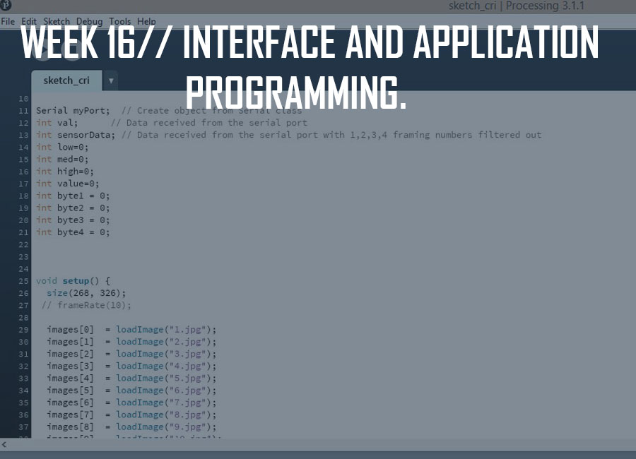
The second trial I did was the sequential example from the examples in the processing software, by going to:
File-->Examples-->Topics-->Animation-->Sequential
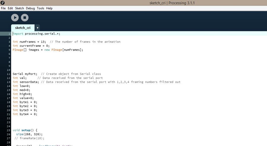
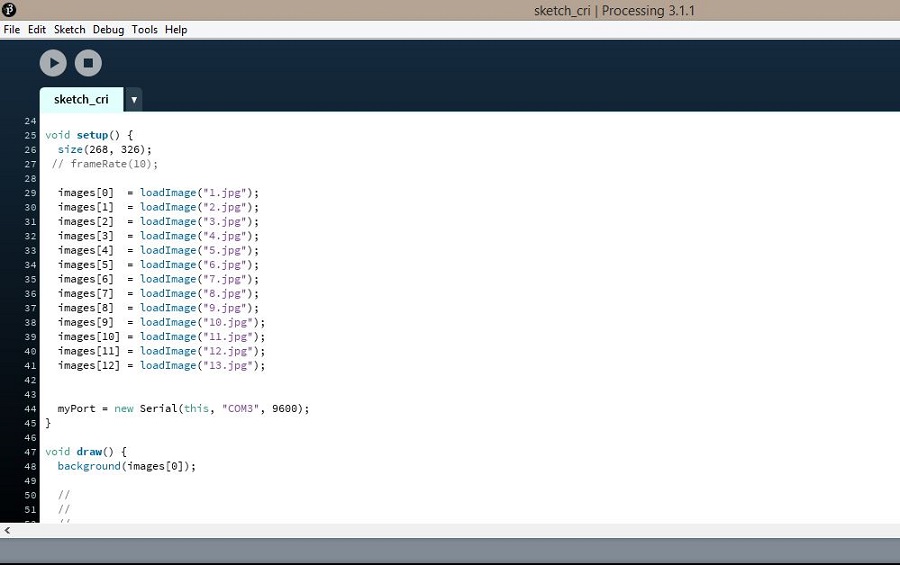
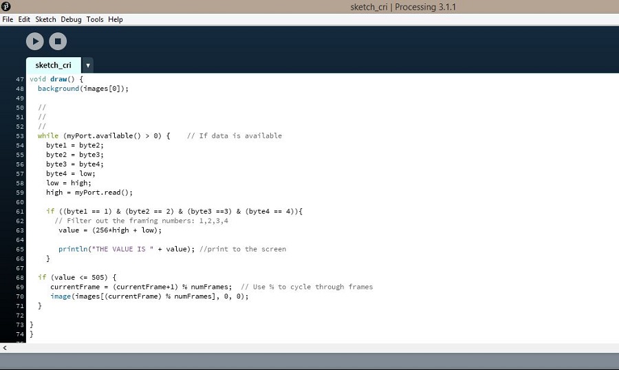
After downloading a .gif file of "le Cri" from Edvard Munch, I inserted the different frames so as to have an illusion of motion when speaking into the microphone, and modified the code by adding the lines below.
Here is the modified sequential code for this sketch:
import processing.serial.*; int numFrames = 13; // The number of frames in the animation int currentFrame = 0; PImage[] images = new PImage[numFrames]; Serial myPort; // Create object from Serial class int val; // Data received from the serial port int sensorData; // Data received from the serial port with 1,2,3,4 framing numbers filtered out int low=0; int med=0; int high=0; int value=0; int byte1 = 0; int byte2 = 0; int byte3 = 0; int byte4 = 0; void setup() { size(268, 326); // frameRate(10); images[0] = loadImage("1.jpg"); images[1] = loadImage("2.jpg"); images[2] = loadImage("3.jpg"); images[3] = loadImage("4.jpg"); images[4] = loadImage("5.jpg"); images[5] = loadImage("6.jpg"); images[6] = loadImage("7.jpg"); images[7] = loadImage("8.jpg"); images[8] = loadImage("9.jpg"); images[9] = loadImage("10.jpg"); images[10] = loadImage("11.jpg"); images[11] = loadImage("12.jpg"); images[12] = loadImage("13.jpg"); myPort = new Serial(this, "COM3", 9600); } void draw() { background(images[0]); // // // while (myPort.available() > 0) { // If data is available byte1 = byte2; byte2 = byte3; byte3 = byte4; byte4 = low; low = high; high = myPort.read(); if ((byte1 == 1) & (byte2 == 2) & (byte3 ==3) & (byte4 == 4)){ // Filter out the framing numbers: 1,2,3,4 value = (256*high + low); println("THE VALUE IS " + value); //print to the screen } if (value <= 505) { currentFrame = (currentFrame+1) % numFrames; // Use % to cycle through frames image(images[(currentFrame) % numFrames], 0, 0); } } }This is an hommage to my tutors, Santi an Ferdi, whom we shower with questions all day long :)
"Le Cri" Processing sketch from Elissa Sophia Assaf on Vimeo.
Clearly, I'm not good at whistling -_-
You can download the processing sketches files here.
This week's assignment was to propose a final project that integrates the range of units covered, answering the questions below.
We started off the week with the usual lecture going over a range of fab academy projects with Neil Gershenfeld.
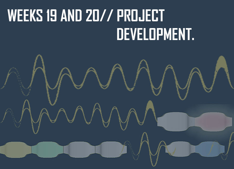
Sound-Controlled Light Display
This prototype through interaction with its surroundings would be depicting as well as enhancing an atmosphere at a given time and space with a lighting game of warm and cool tone colors, translating for instance the multiple sounds of percussion instruments into different colors of light in separate modules depending on the pitch of the sound wave, hence coding the beats into light and resulting only from the interaction of the players with this prototype.
Trees are known to "absorb" soundwaves, noise and air pollution and in this case, assembling the different-sized modules on a vertical plane would generate an outline that resembles that of willow trees.
Beyond this prototype, the aim of that product is to be a kit with numerous modules to be assembled as pleased by the user so as to create an interactive customizable light display.
On a larger scale:
São Paulo LED building façade shines a light on noise and pollution`
A new reactive LED façade has been installed at the Hotel WZ Jardins in São Paulo, Brazil. The façade responds to sounds, air quality and people's interaction with a smartphone app. It is part of a project that explores the "Hacked City" and how technology can bring positive change to cities.
Like the façade at the Ontario College of Art and Design University , the design is based on data derived from the local area. The metal skin was based on the audio waveform of the surrounding soundscape over the course of 24 hours, showing the ebb and flow of city life.
The waveform was then translated to a color-coded sheet of metal pixels that was subsequently wrapped around the 30-story building, rising upwards in a spiral. The blue, gray and gold skin provides a colorful intervention in an otherwise grey cityscape during the day.
At night, the building comes alive with 200 strips of low-energy LEDs rising up the building and interspersing illumination throughout the façade. The accompanying smartphone app allows users to interact with the façade by voice or simply by moving their fingers across the screen of their device, while different sensors cause the LED lighting to react to different stimuli in real time.
Microphones installed around the building pick up noise to which the movement and shape of the illuminated LEDs react. Air quality sensors, meanwhile, monitor real-time changes in the local air quality and these are translated into different colors of LED illumination. Warmer tones, such as red and oranges, indicate polluted air, while cooler tones, such as blues and greens, are shown when the air quality improves.
This BOM was modified after the "final" prototype was made.
Composites:
Foam
Textile
Breather material/release film/ perforated film
Epoxy and Hardener
(Gloves:mandatory/scale/plastic cup/stick for stirring)
3D Printing:
ABS or PLA 3mm filament
(Spray for preparing the base)
Electronics:
Female-Male wires
Male-male wires
PCB boards
Solder
Components:
RGB led
Electret microphone
ATtiny 32u4
Amplificator
1UF capacitors
0.1UF capacitors
18PF capacitors
680 ohm resistor
220 ohm resistors
20 ohm resisotrs
10k resistors
1k resistor
16 Hz Crystal
Female and male pin headers
USB connector
For the rest:
Magnets
White filament
2x3V batteries (per module)
Procuring the parts:
The lab provides us with most of the material, but maily the components pcb boards, solder and soldering equipment for the electronics and in my case the components were all available in the fab invertory, the mosst expensive one being the attiny 32u4 microcontroller which costs 6 euros.
The Epoxy resin and hardener, as well as the fabric necessary for making the composites were also available at the lab, and I was left to buy the specific thin fabric I was going to use which cost me 4 euros for the meter, and the white textile filament both from the Ribes and Casals store, as well as the magnets for 1,60 euros from a supply store nearby..
The PLA and ABS filament for 3D printing were also procured by the lab, and since the base weighed 0.6g, the approximate price for the 3d printed part is 3,60 euros.
Here is the Fab Lab inventory for a more detailed list of prices for the hardware and products available at the lab.
Total Cost:
The cost will be evaluated per module, and seeing as I have no relatively pricey parts, I could evaluate the price to an approximate 25€/per module which is a satisfying result for me since the aim of that product is to be a kit with numerous modules to be assembled as pleased by the user so as to create an interactive customizable light display.
This list was modified after the "final" prototype was made.
Electronics:
Attiny 32u4 microcontroller board
Electret microphone breakout input board
RGB led breakout output board
5V voltage regulator board with switch
2x3V batteries (per module)
Model/Casing
Composites "shell"
3D printed base
Softwares:
3D Modeling(Rhino)
CAM Programs for 2D and 3D Milling(Partworks/RhinoCam)
Eagle for Electronics Design
Fabmodules for pcb milling
Cura for 3D Printing
Arduino IDE for Programming
Since I had also started working on another concept for this display which was an 8-bit "Beeping Willow", that consisted of the same display of modules lighting and producing 8-bit sounds based on the mozzi library for arduino, through an interface Katerina was working on, and since I was running out of time and wanted to proceed with the actualization of my initial concept, I just focused on the latter but had already spent considerable amount of time on the other one so I was left with two weeks to have a working prototype.
Fortunately, the design and models I had already worked on previously were the same for both concepts, so now I was left with the model and electronics fabrication, as well as the programming, on which I would be working simultaneously, electronics design and programming being the most time-consuming.
Here is the hackpad page where I had documented my research for the "Beeping Willow" project: View FINAL PROJECT: on Hackpad.
Should I work on seperate modules with seperate microcontroller boards, to go with my concept, or try working a serial communication between them?
// Is the electret microphone board with the amplifier adequate to get an accurate detection of different frequencies?
// Which libraries will I be using to detect the different beats?
Which microcontroller should I use depending on the number of input/output pins needed and space needed for the libraries?
Which fabric/material thickness should I use to get a smooth filtering of the light?
How accurate and neat is the finishing of the composites going to turn out?
Which will be the design of my final board or boards in order to embed them in the bottom 3D-printed casing?
How many modules will I be able to fabricate in this short period of time?
Am I too laid back?
The prototype will be functional when detecting different soundwaves from beats and translating them into different color tones.
Eventually, I would like to further explore the FFT library and Beat Detection algorithms to be able to customize the modules as I please, which would maybe require better microphones (and potentiometers).
This week's assignment was to create and document a license for the final project and develop a plan for dissemination.
We started off the week with a very interesting introduction to invention, intellectual property, and income with Neil Gershenfeld.
Since my first studies were Law studies, the notions weren't alien to me, and it was very interesting to read about this new approach.
To further gain an understanding about licenses and patents, I read about the ones mentioned in the lecture from the MIT page.
The MIT License (MIT): Permission is granted, free of charge, to any person obtaining a copy of this software and associated documentation files (the "Software"), to deal in the Software without restriction, including without limitation the rights to use, copy, modify, merge, publish, distribute, sublicense, and/or sell copies of the Software, and to permit persons to whom the Software is furnished to do so, subject to the following conditions.
"This work may be reproduced, modified, distributed, performed, and displayed for any purpose, but must acknowledge "project name". Copyright is retained and must be preserved. The work is provided as is; no warranty is provided, and users accept all liability."
The BSD license: Actively involved in Open Source community-building, education, and public advocacy to promote awareness and the importance of non-proprietary software.
Their mission: Open source enables a development method for software that harnesses the power of distributed peer review and transparency of process. The promise of open source is higher quality, better reliability, greater flexibility, lower cost, and an end to predatory vendor lock-in.
For sharing softwares.
It states: "The GNU General Public License is a free, copyleft license for software and other kinds of works. The licenses for most software and other practical works are designed to take away your freedom to share and change the works. By contrast, the GNU General Public License is intended to guarantee your freedom to share and change all versions of a program--to make sure it remains free software for all its users. We, the Free Software Foundation, use the GNU General Public License for most of our software; it applies also to any other work released this way by its authors. You can apply it to your programs, too. When we speak of free software, we are referring to freedom, not price. Our General Public Licenses are designed to make sure that you have the freedom to distribute copies of free software (and charge for them if you wish), that you receive source code or can get it if you want it, that you can change the software or use pieces of it in new free programs, and that you know you can do these things. To protect your rights, we need to prevent others from denying you these rights or asking you to surrender the rights. Therefore, you have certain responsibilities if you distribute copies of the software, or if you modify it: responsibilities to respect the freedom of others. For example, if you distribute copies of such a program, whether gratis or for a fee, you must pass on to the recipients the same freedoms that you received. You must make sure that they, too, receive or can get the source code. And you must show them these terms so they know their rights."
Provides a foundation for open, collaborative software development projects by supplying hardware, communication, and business infrastructure
Creates an independent legal entity to which companies and individuals can donate resources and be assured that those resources will be used for the public benefit.
Provides a means for individual volunteers to be sheltered from legal suits directed at the Foundation's projects.
Protects the 'Apache' brand, as applied to its software products, from being abused by other organizations.
Creative Commons helps you legally share your knowledge and creativity to build a more equitable, accessible, and innovative world — unlocking the full potential of the internet to drive a new era of development, growth and productivity.
"The work may be reproduced, modified, distributed, performed, and displayed for any purpose, but must acknowledge the "project name". Copyright is retained and must be preserved. The work is provided as is; no warranty is provided, and users accept all liability."
The aim behind my project was rather in the process than the end product, by inputting the technical, mechanical and digital skills acquired during the past weeks into an abstract idea to go forward with the actualization of the prototype.
I can only claim the copyright for the design and the concept (although sound-activated light displays are common), because I have modified already existing codes and redesigned the boards for the electronics.
Since I don't plan on working further on this specific project, I wouldn't mind seeing it readapted, remixed, transformed into a better version I could enjoy using one day!
Sometimes, commercialisation is a good incentive to further developing and perfecting a project, given of course that the link to the original license is provided, which allows to share and adapt, promoting by doing so the open-source culture.
Therefore, The license I chose for "Lighting Willow" is a Creative Commons license.
It states:
"You are free to: Share — copy and redistribute the material in any medium or format Adapt — remix, transform, and build upon the material for any purpose, even commercially. The licensor cannot revoke these freedoms as long as you follow the license terms. Under the following terms: Attribution — You must give appropriate credit, provide a link to the license, and indicate if changes were made. You may do so in any reasonable manner, but not in any way that suggests the licensor endorses you or your use. No additional restrictions — You may not apply legal terms or technological measures that legally restrict others from doing anything the license permits. Notices: You do not have to comply with the license for elements of the material in the public domain or where your use is permitted by an applicable exception or limitation. No warranties are given. The license may not give you all of the permissions necessary for your intended use. For example, other rights such as publicity, privacy, or moral rights may limit how you use the material."

This work is licensed under a Creative Commons Attribution 4.0 International License.
This prototype through interaction with its surroundings would be depicting as well as enhancing an atmosphere at a given time and space with a lighting game of warm and cool tone colors, translating for instance the multiple sounds of percussion instruments into different colors of light in separate modules depending on the pitch of the sound wave, hence coding the beats into light and resulting only from the interaction of the players with this prototype.
Trees are known to "absorb" soundwaves, noise and air pollution and in this case, assembling the different-sized modules on a vertical plane would generate an outline that resembles that of willow trees :)
Beyond this prototype, the aim of that product is to be a kit with numerous modules to be assembled as pleased by the user so as to create an interactive customizable light display.
Further information about the concept is found in the Applications and Implications week, and Invention, Intellectual Property, and Income week.
Rhinoceros
RhinoCam
Cura
Eagle
Arduino IDE
fabmodules
Photoshop
Gimp
Electronics:
Attiny 32u4 microcontroller board
Electret microphone breakout board
RGB led breakout board
5V voltage regulator board with switch
2x3V batteries (per module)
Model/Casing
Composites "shell"
3D printed base
Machines
Roland SRM-20 milling machine
Mars3 3 axis Precix milling machine
Reprap 3D printer
Air compressor/Vacuum
Composites:
Foam
Textile
Breather material/release film/ perforated film
Epoxy and Hardener
3D Printing:
ABS or PLA 3mm filament
Electronics:
Female-Male wires
Male-male wires
PCB boards
Solder
Components:
RGB led
Electret microphone
ATtiny 32u4
Amplificator
1UF capacitors
0.1UF capacitors
18PF capacitors
680 ohm resistor
220 ohm resistors
20 ohm resisotrs
10k resistors
1k resistor
16 Hz Crystal
Female and male pin headers
USB connector
For the rest:
Magnets
White filament
2x3V batteries (per module)
(since my phone was stolen in the last week before the 8th of july, a lot of pictures and videos from my documentation were lost)
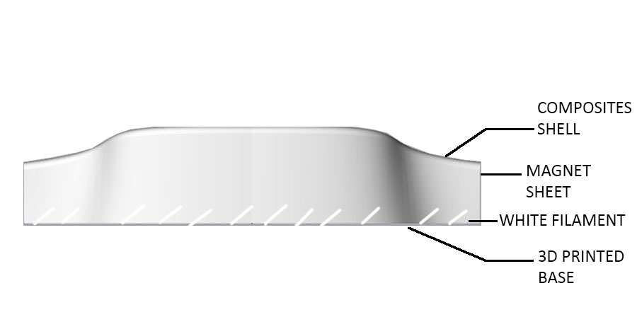
I started by designing the model based on the outline I had in mind, using Rhino as a 3D modeling software.

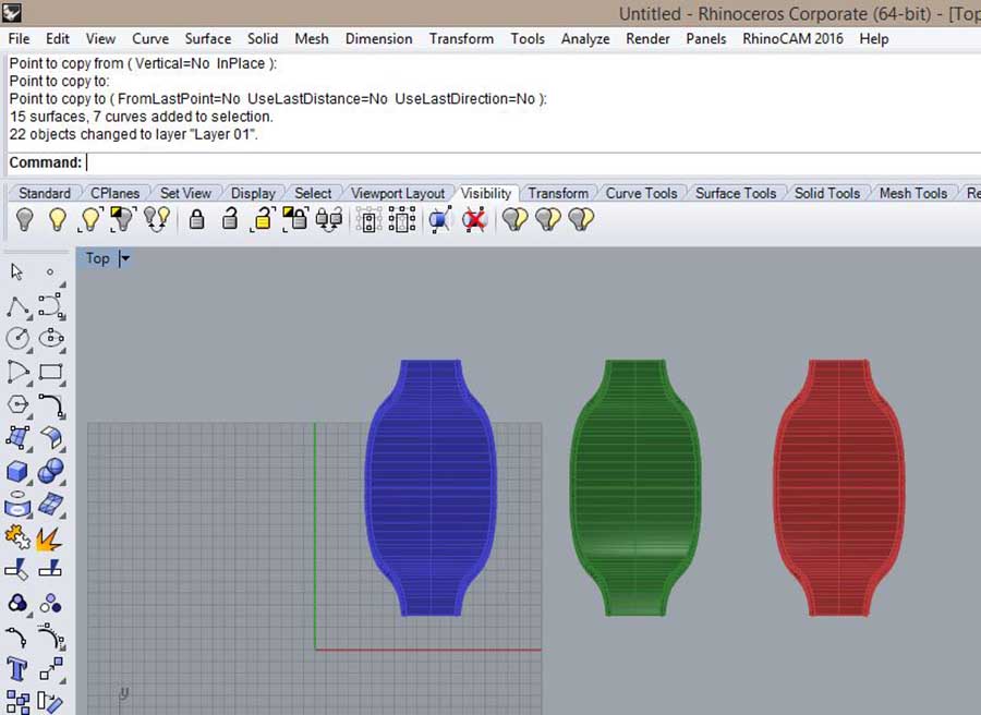
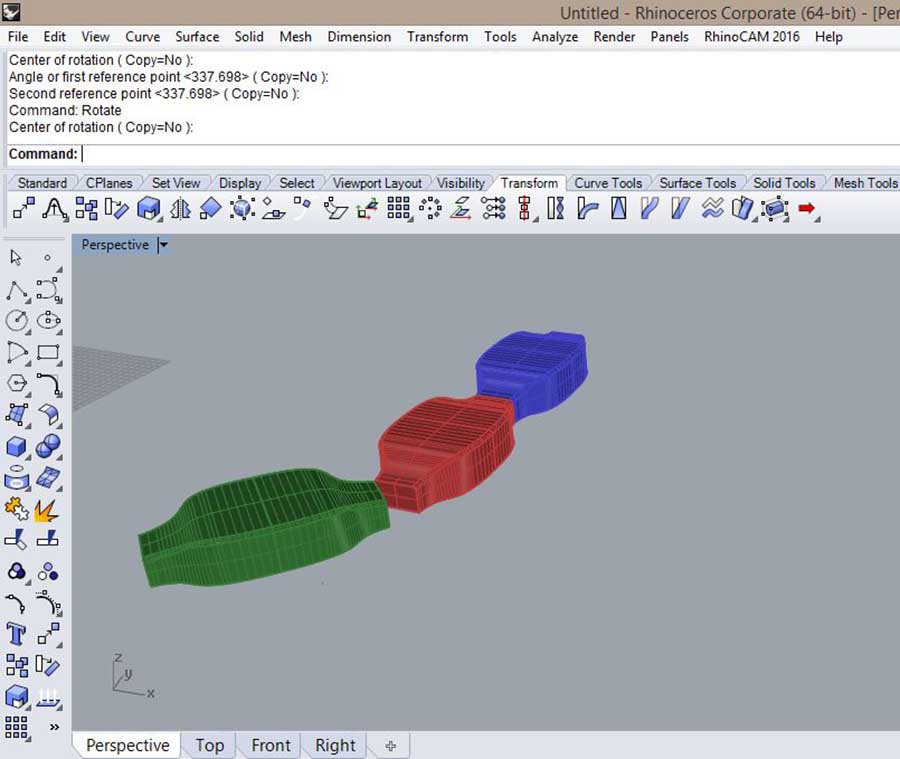
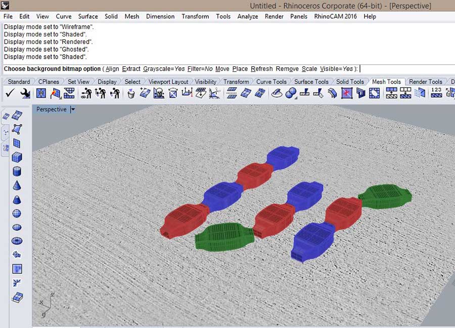
I decided to 3D print the base for the model, and tried the first one with white PLA filament and the second with ABS filament, using the RepRap 3D printing machine. I would have liked to add a casing incorporated in the base to embed the electronics but the problem was that i didn't know how many boards I would have until the end, since I had initially designed one board with sound input and light output and ended up having them as breakout boards.
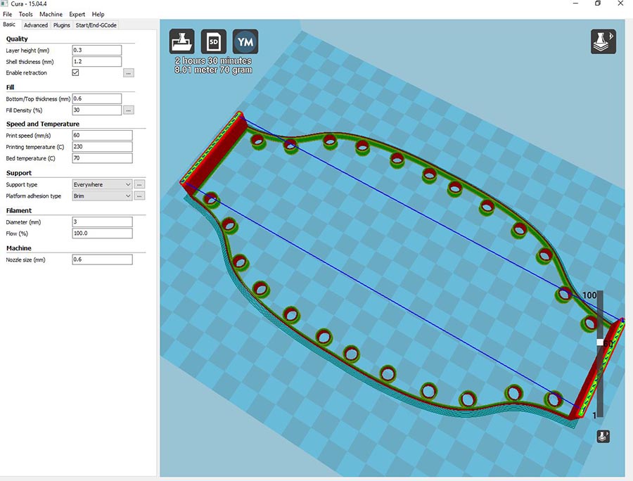
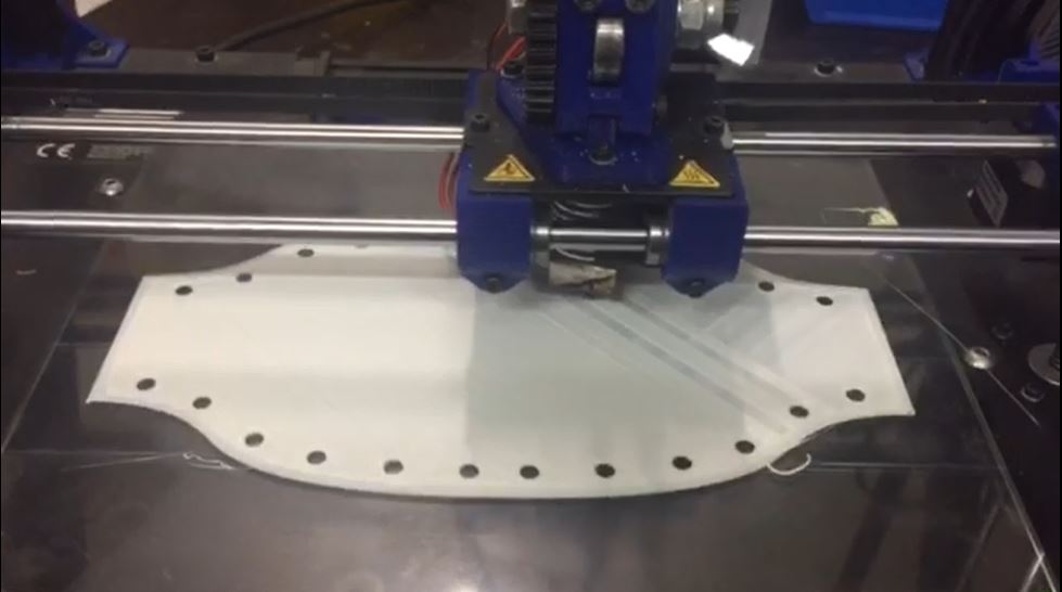
As for the shell top part, I started by cleaning the surfaces and joined them into one polysurface to be able to produce the gcode on RhinoCam, for milling the foam using the precix 3D-axis milling machine.
In order to make the shell translucid, I used three layers of very thin white fabric for the first module, and four layers of another kind of fabric for the other module and the finishing of the second one turned out to give a nicer filtering of the light, although as a final outcome, the shell turned out to be mildly yellowish and not white because of the resin (which was expected).
One RGB led light though was not enough to get nice homogeneously spread light.
RhinoCam settings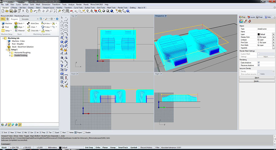 Vacuum bagging process
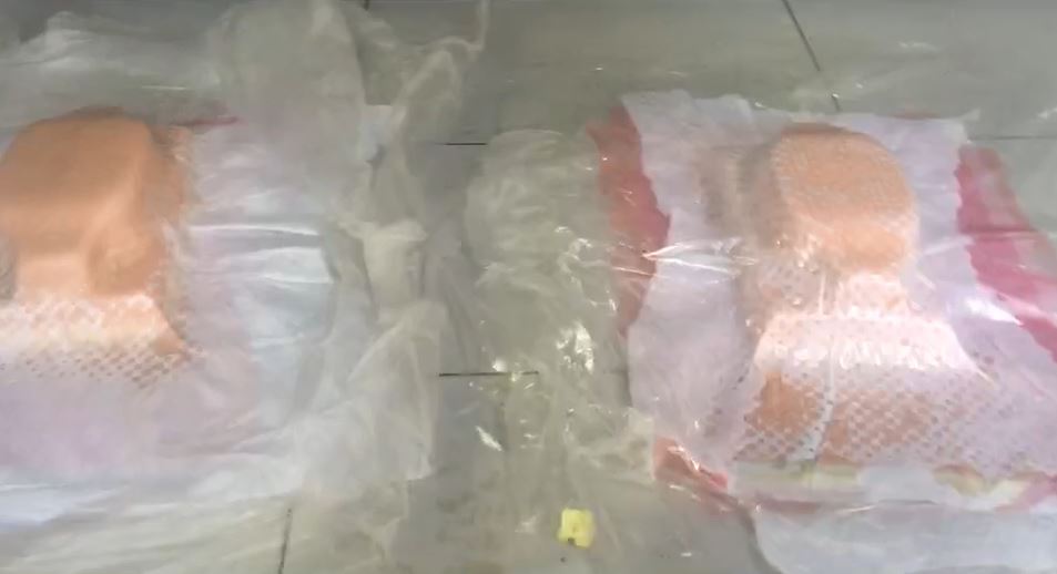 Sanding
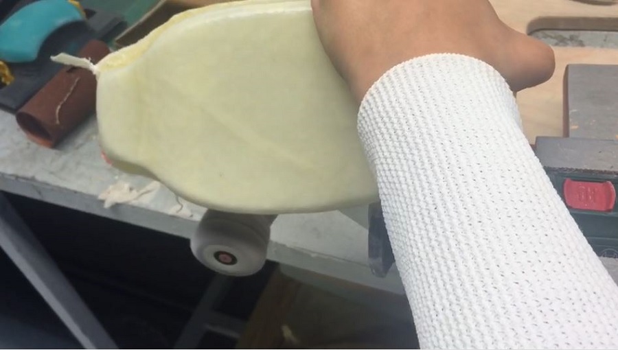
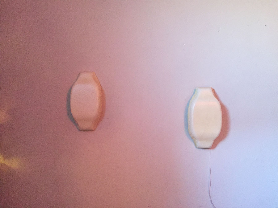
You can find a more detailed explanation of producing the Gcode, using the 3D-axis milling machine and steps to making the composites in the "Composites" week assignment.
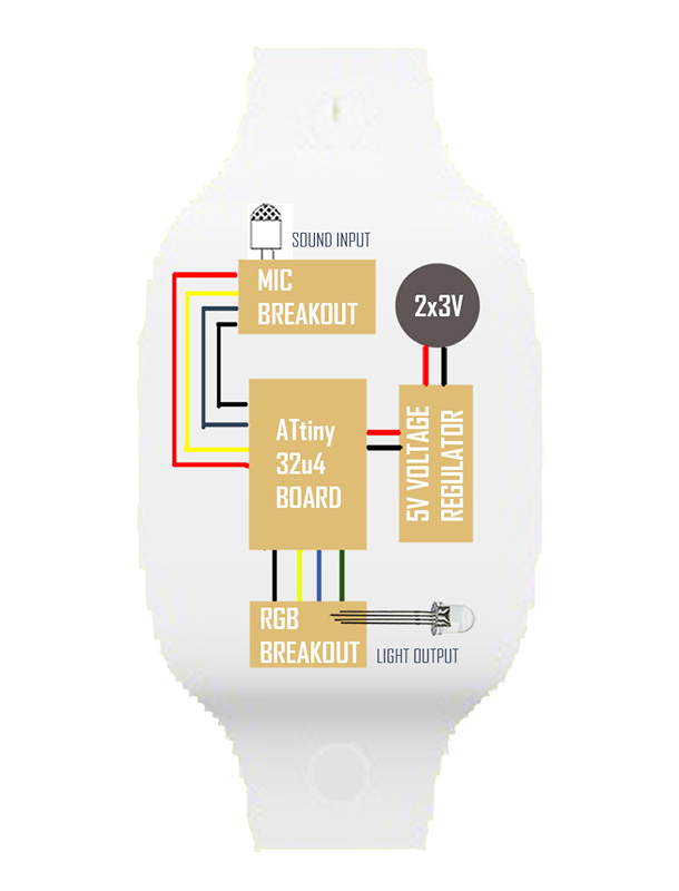
I had started by designing a board on Eagle incorporating both sound input and light output, but had first ran a test with an electret mic opamp input board based on Neil's board design, that I redesigned milled and soldered, and then connected to an arduino uno.
I had a lot of trouble getting any accurate values when running serial monitor and could only visualize the changes in sound via the serial plotter.
I milled and soldered two other electret mic breakout boards based on two other board designs i had looked up and still had the same problem, only to realize after testing the boards at home that the problem was from all the noise at lab. That is when I realized how noisy our lab is with 2 CNC milling machines, the laser-cutters, the 3D printing machines, the sanding machine and 18 students.
It also hit me how silent and sad it's going to be when the fab academy is over.
These microphone boards are very sensitive to sound and can only be tested in silent spaces which also made me think about how I could incorporate the display as a museum installation.
"The human listening system determines the rhythm of music by detecting a pseudo periodical succession of beats. The signal which is intercepted by the ear contains a certain energy, this energy is converted into an electrical signal which the brain interprets. Obviously, The more energy the sound transports, the louder the sound will seem. But a sound will be heard as a beat only if its energy is largely superior to the sound's energy history, that is to say if the brain detects a brutal variation in sound energy. Therefore if the ear intercepts a monotonous sound with sometimes big energy peaks it will detect beats, however, if you play a continuous loud sound you will not perceive any beats. Thus, the beats are big variations of sound energy."
Another solution I assume would have been adding automatic gain control to the opamp or adding potentiometers to be able to better filter and denoise the sound.
Wind, noise, and air density changes affect the strength and cleanness of the audio signal in between the emitter and receptor.
On the other hand, if you use the microphone in a closed and large enough room, it works better. Emitting at least three different frequencies may also help positionning the receiver, and filtering them using the FFT library helps prevent sound mix.
Light+Sound Breakout Board Schematics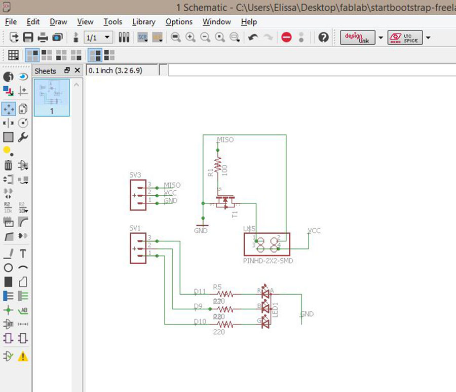 Light+Sound Breakout Board
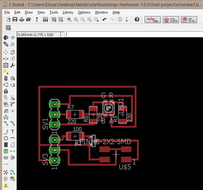 Electret Mic Opamp Breakout Board Trial
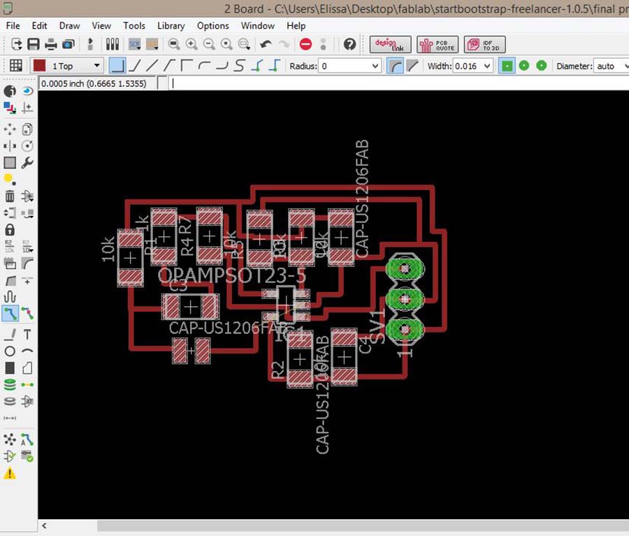 Trials
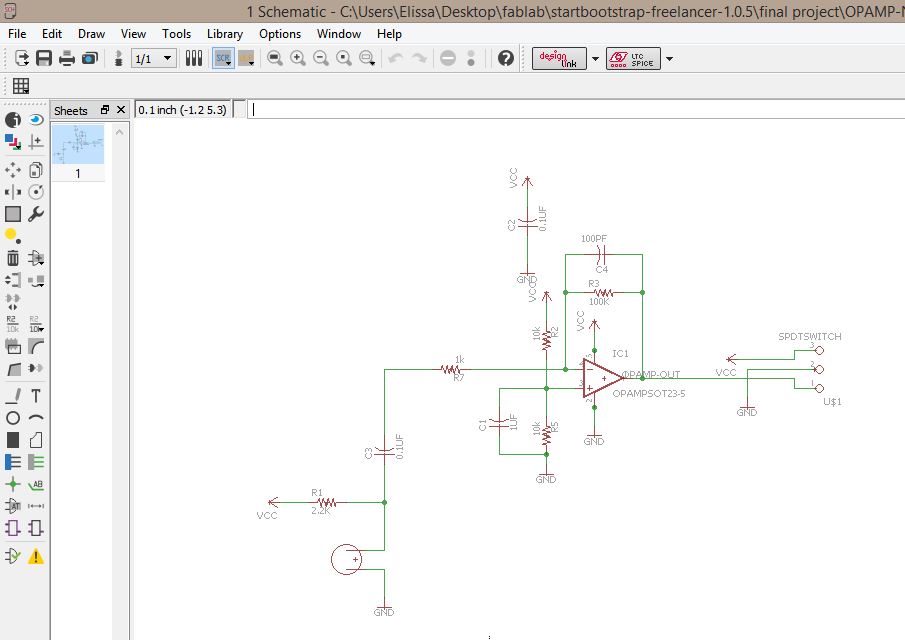
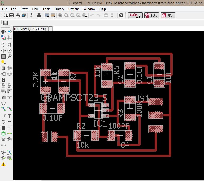
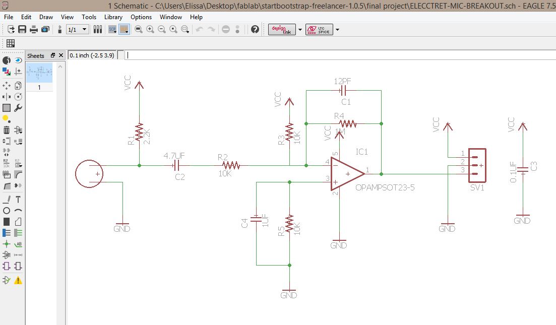
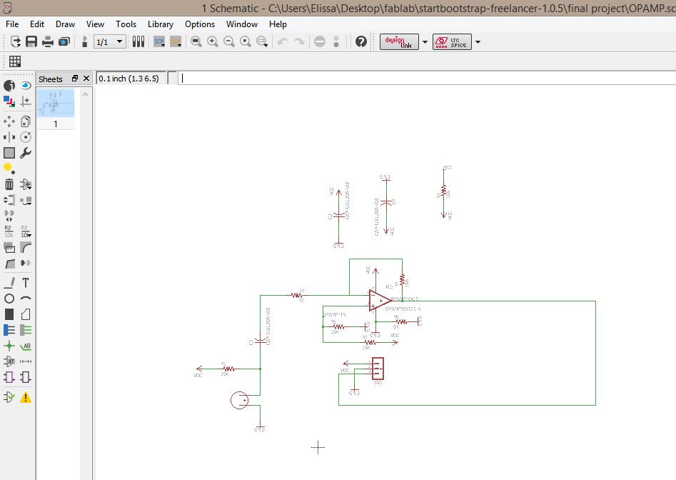 Final Mic Input Sound Breakout Board Traces
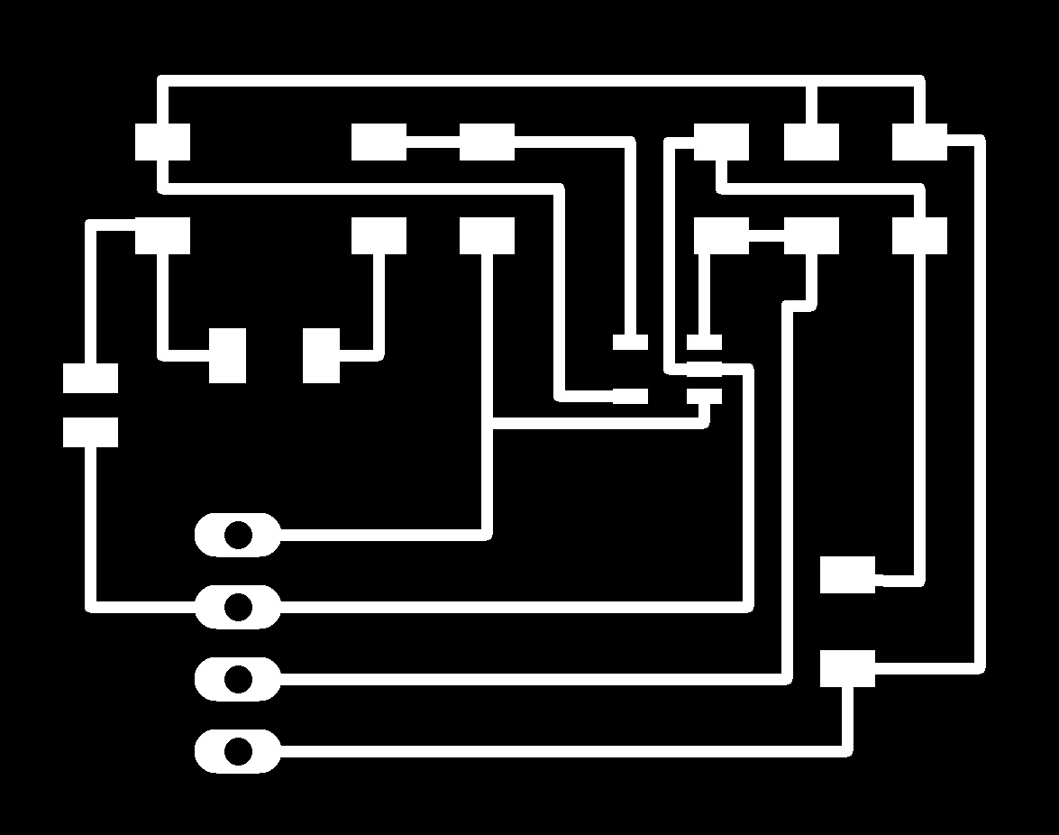 RGB led output schematics
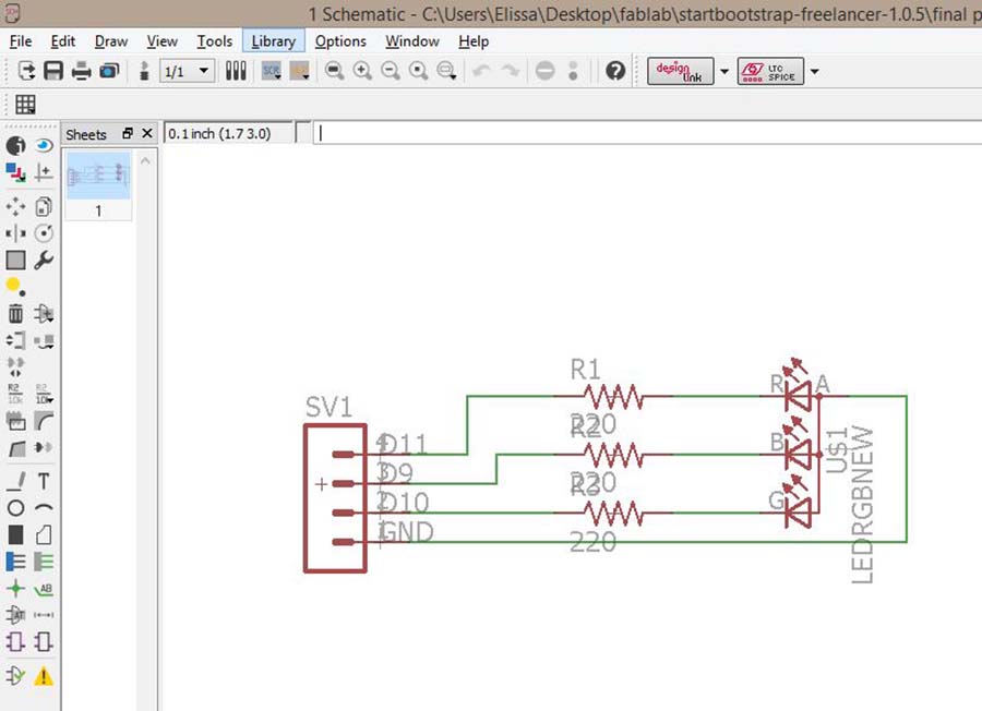 RGB led output board
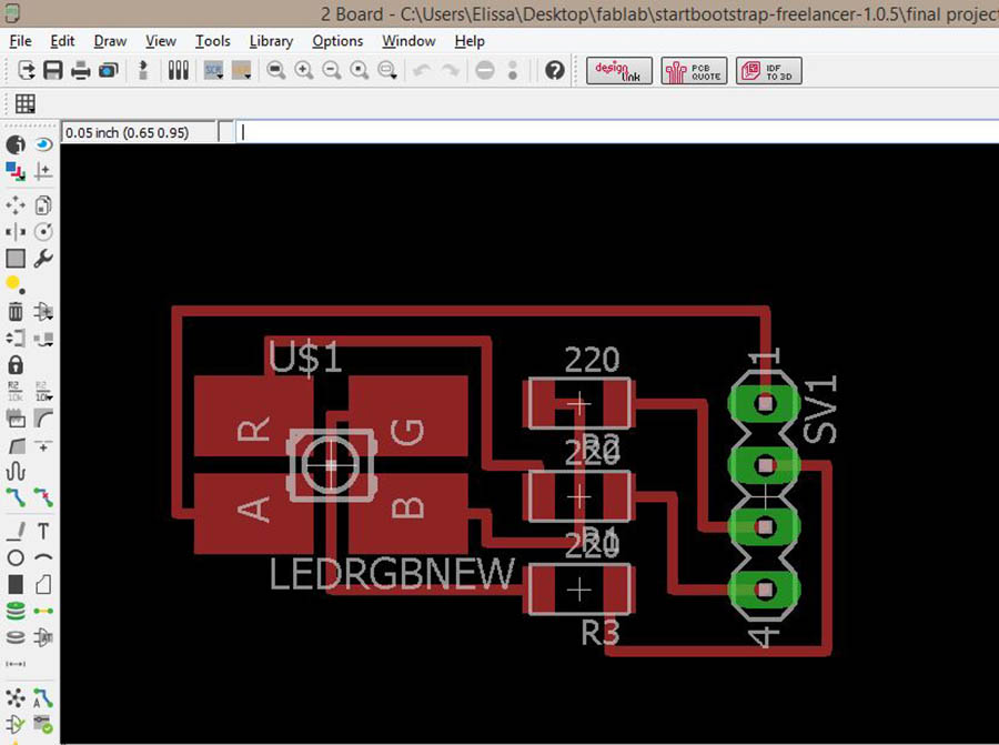 RGB led output traces

By then I had already redesigned an Arduino Leonardo based on Jonathan Minchin's FabLeo board using an ATtiny 32u4 microcontroller, so as to have my own Arduino I could reuse for other purposes later, and another one with fewer pins, 2 for the sound and 3 for the RGB led, also to be able to have enough space to use the libraries I wanted to try out.
I troubleshooted both and had trouble with the first one even after checking all the connexions were okay but it turned out the microcontroller had some pins that weren't soldered well enough to the board.
This Schematic is very helpful for recognizing the pins and understanding how the microcontroller works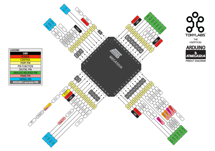 Fableo Traces
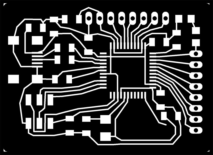 Fableo redesigned with fewer pins Schematics
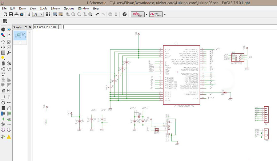 Fableo redesigned with fewer pins
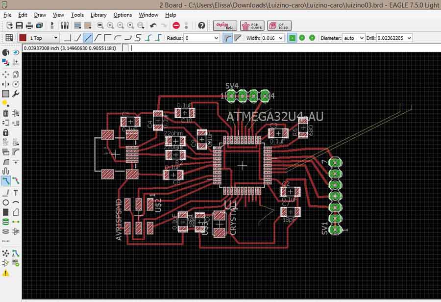
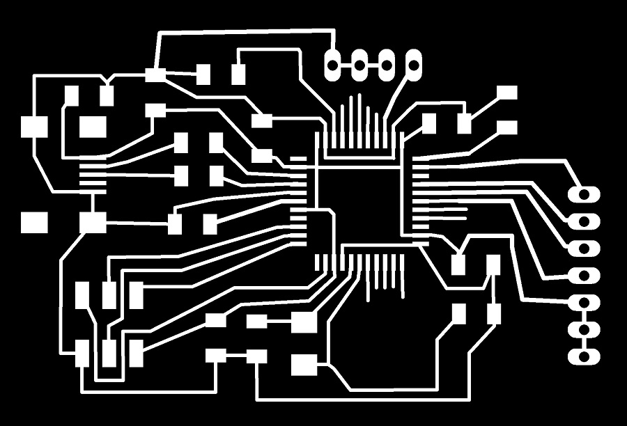
I then was able to burn the bootloader for both.
ATtiny 32u4 board bootloader burned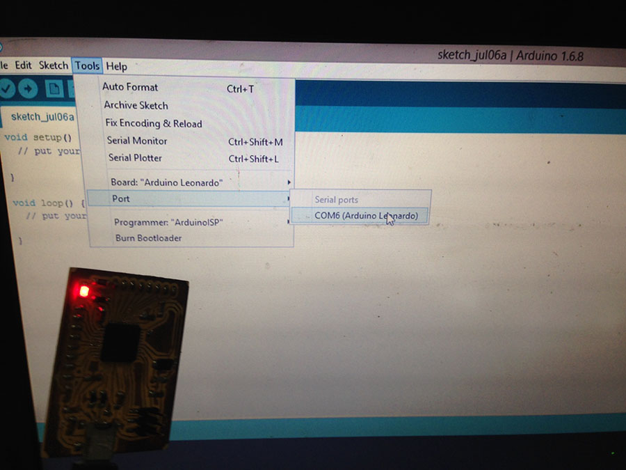 ATtiny 32u4 board bootloader burned/ led removed
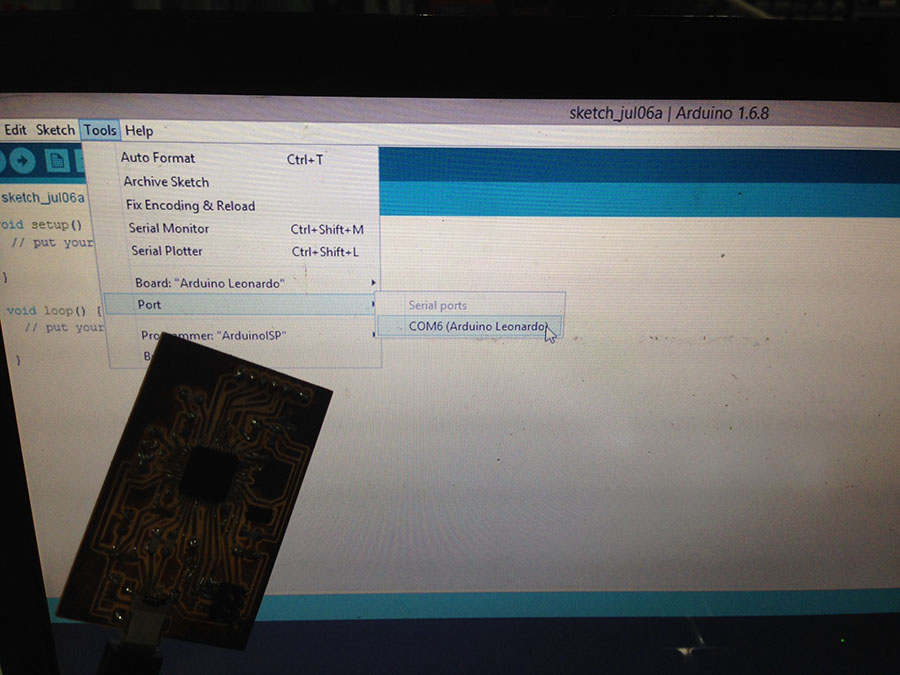
To power the circuit, I needed a 5V current, so I got two 2x3V batteries with casing, and used Xavi Dominguez's 5V voltage regulator board design, with a switch.
ATtiny 32u4 board with rgb breakout board and electret mic breakout board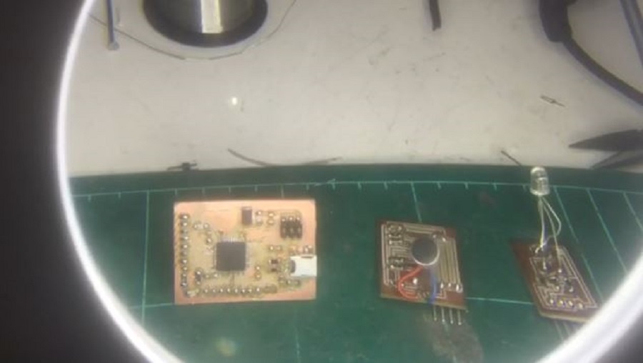 The Two Families
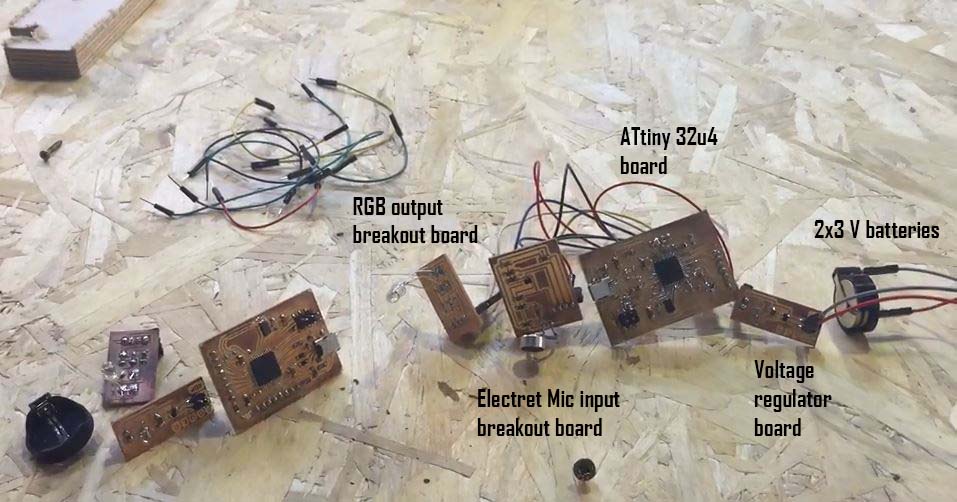
All the while, I was doing a lot of research on using sound as an input with Arduino, testing and getting a sense of up to 10 codes I had researched. My aim was to work with the Fast Fourier Transform algorithms, the FFT library for Arduino.
Here's a very interesting read about Beat Detection on Arduino which explains, how to detect the beat of a music signal through three major approaches.
The BeatDetect aslo allows you to analyze an audio stream for beats (rhythmic onsets). In sound energy mode you use lines to query the algorithm and in frequency energy mode you use lines to query particular frequnecy bands or ranges of frequency bands.
The major problem I had encountered is that the mic boards I was using would deteriorate very rapidly (about 3 days after designing them), so I couldn't even get the same thresholds and got even more inaccurate filtering.
After testing the other ones without having enough time to modify them or get the values I wanted, I ended up working on two simpler codes that I modified so that the color is proportional to the sound pressure and with a smoother RGB led filtering.
Below you can find the two codes I tried, and you can also download the .ino files for the rest of the codes I've tested.
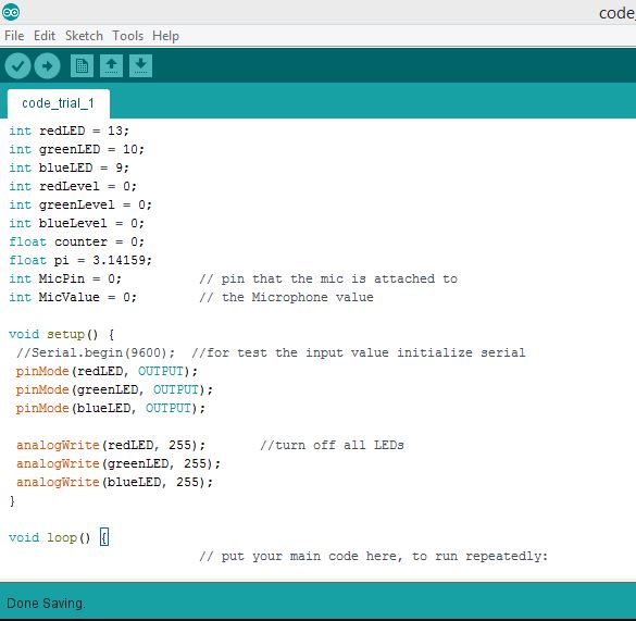
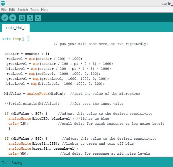
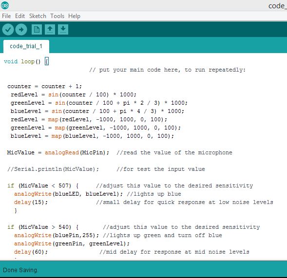
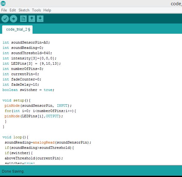
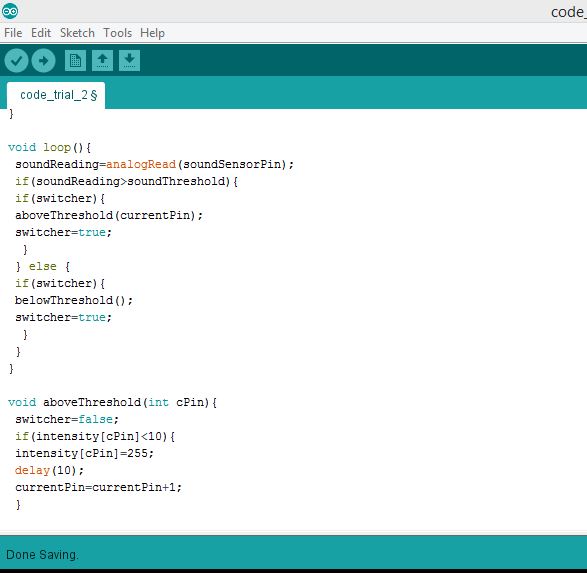
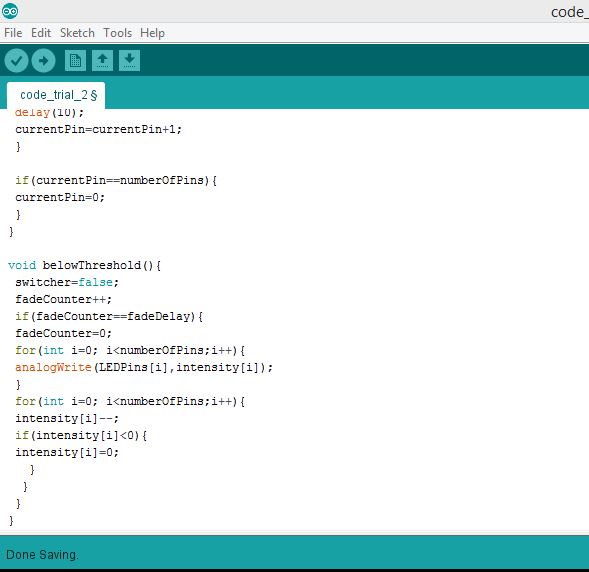

The video below shows the whole process of the final project development.
Final Project Process: Sound-Controlled Light Display "Lighting Willow" from Elissa Sophia Assaf on Vimeo.
This work is licensed under a Creative Commons Attribution 4.0 International License.