Output Devices
MIT'S BRIEFDesign a board with a microcontroller and add an output device.
For this assignment I wanted to redesign the RGB led board. The first step was to have a look at the Hello Rgb Neil's board.
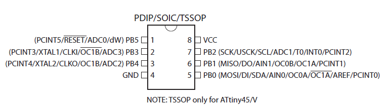
Reading the Datasheet i checked the pinout of the ATtiny 45
Milling And Soldering
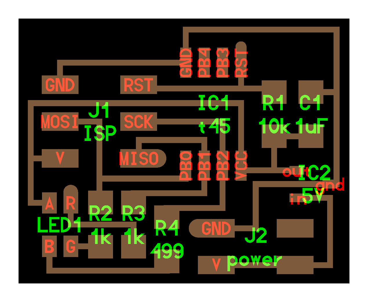
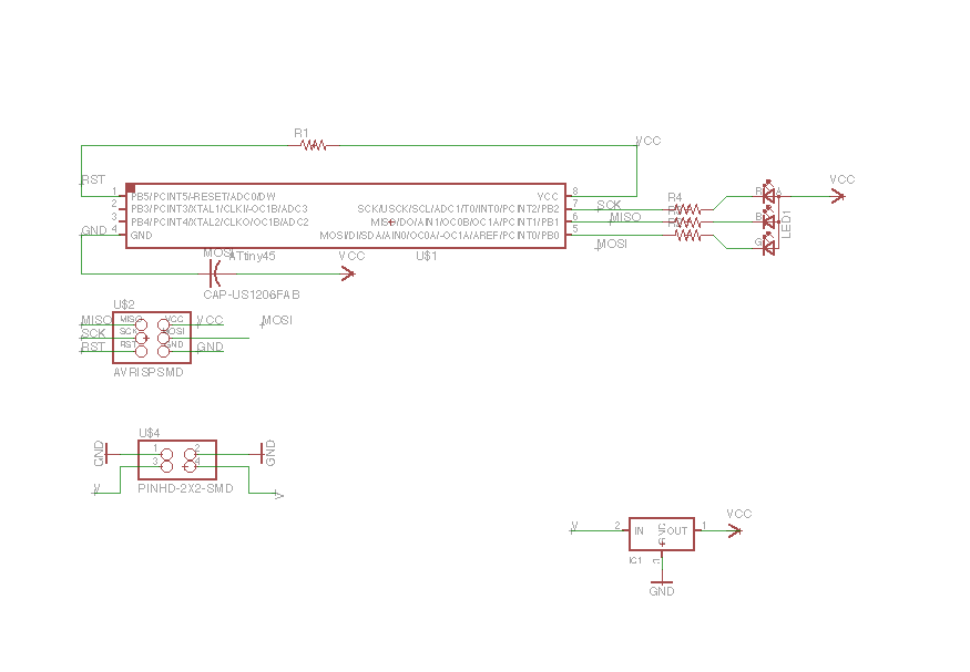
I used Eagle to redesign the board with the following components:
ATtiny 45
4 pin Header
6 pin Programming Head
RGB led
Voltage regulator
(1) 10k Resistor
(2) 1k Resistor
(1)) 499k Ohn Resistor
(1) 1uf Capacitor
Schematic
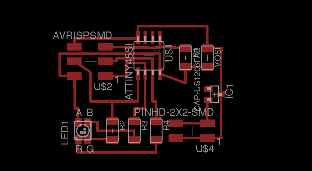
Board
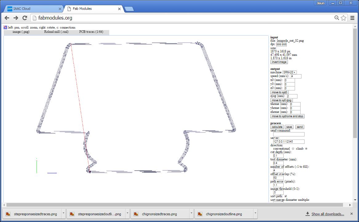
Traces
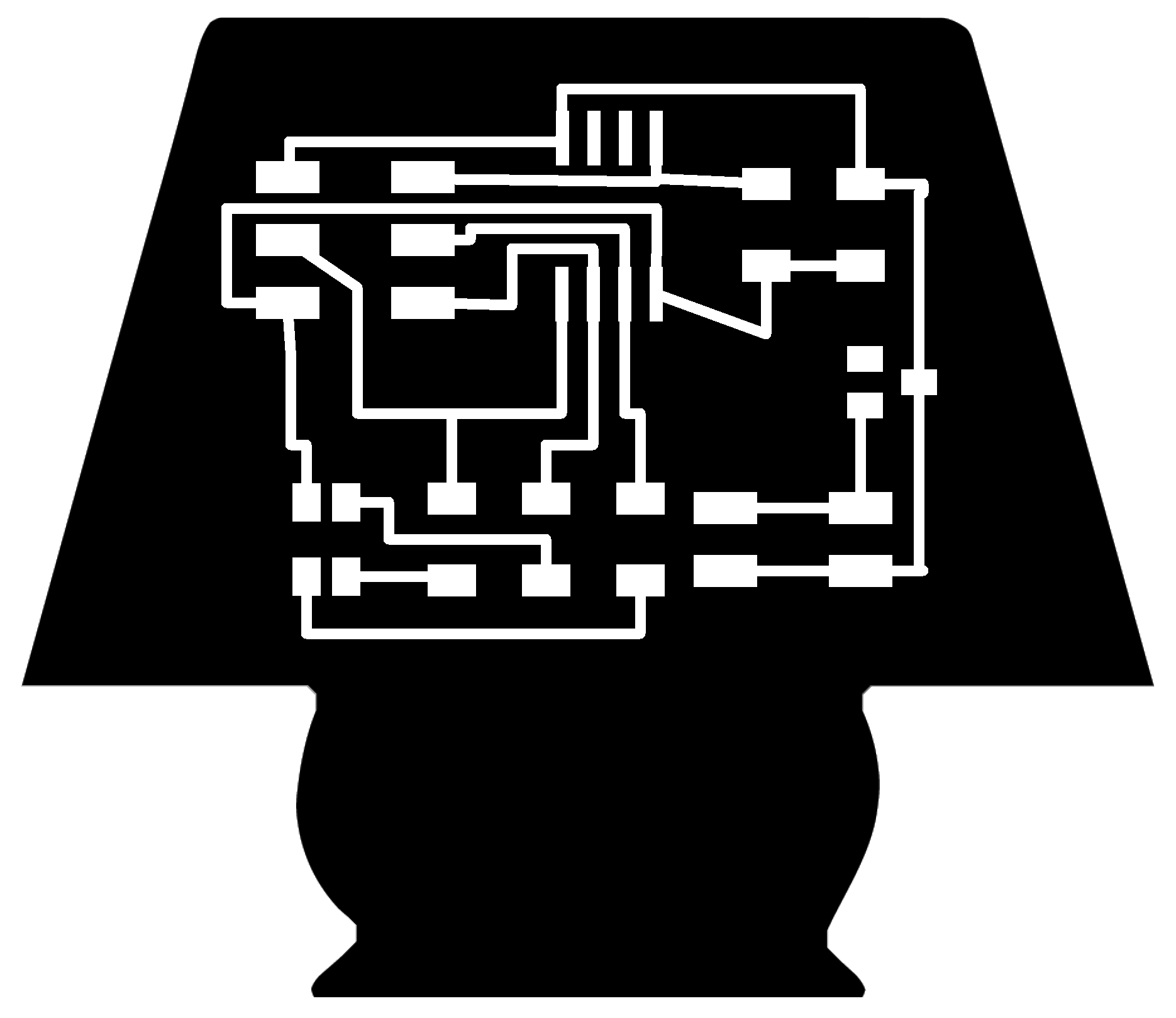
Outline

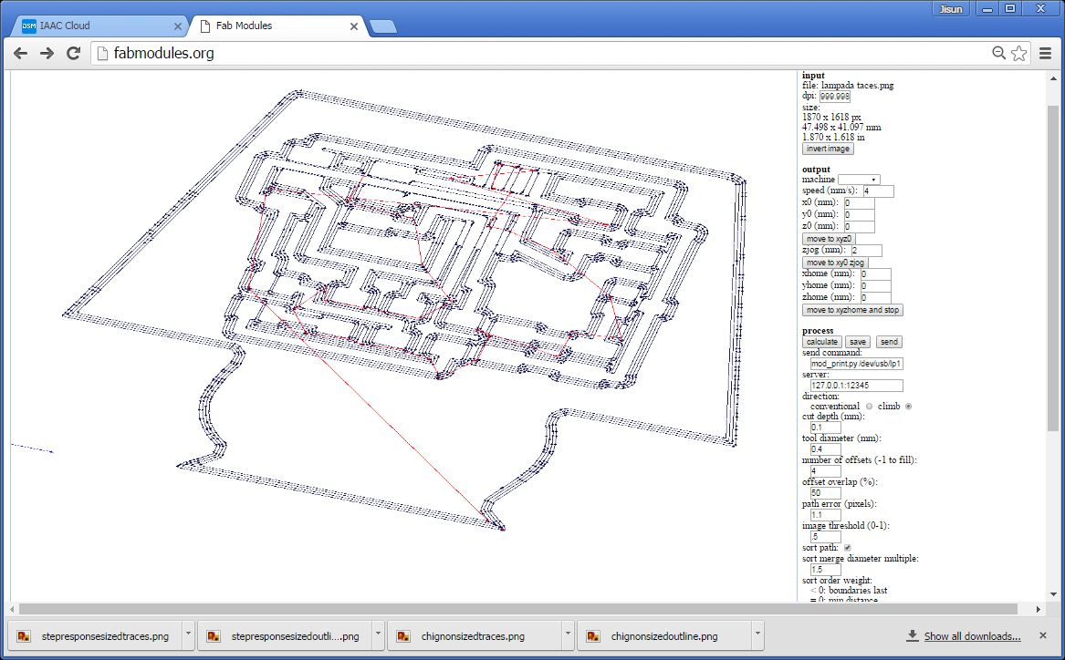
I used the Fab Modules and the ROLAND SRM-20 to mill the board.
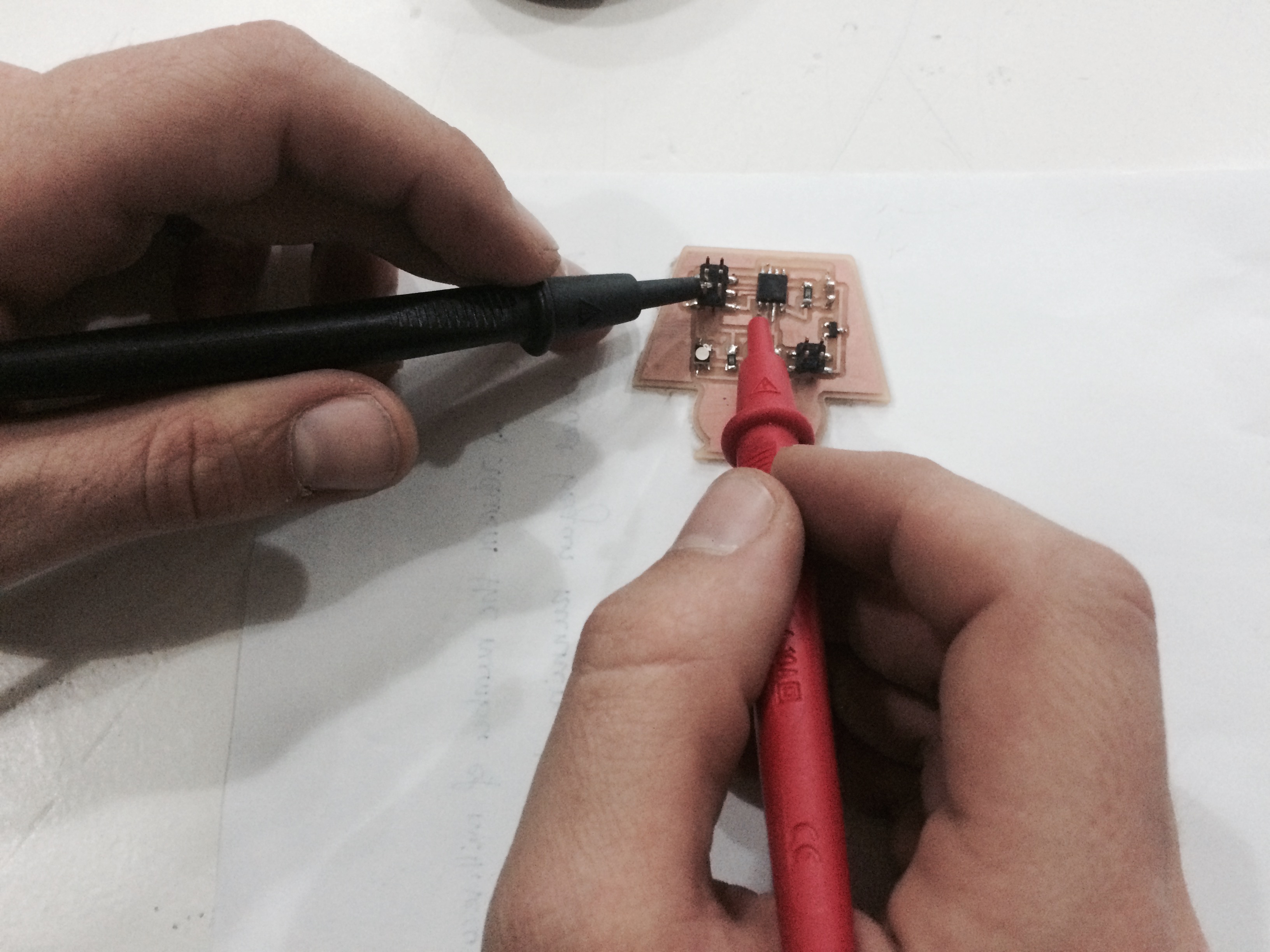
Note: Before soldering I checked the polarity of the RGB led and connected the board to a 5V battery through the 4 pin header with positive pin to V and the negative pin to GND, and used a multimeter to troubleshoot the board and make sure a 5V current is running.
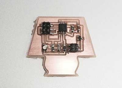
My RGB board
Programming the Board
To program the RGB board I connected the board to the FabISP and since I have an external power supplier connected to the board( check video below) I did not used the FTDI cable to source power.
Then I downloaded these files into the same folder:
- Make file
- C code
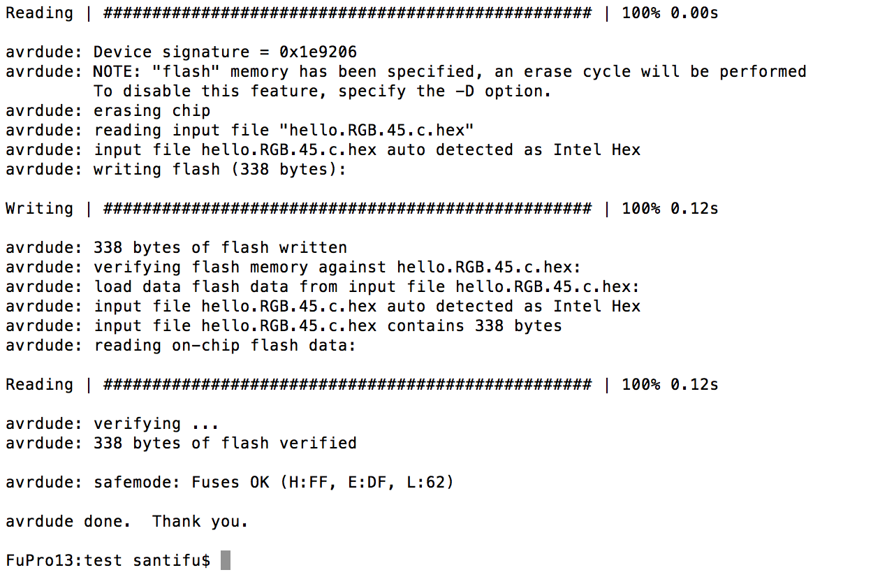
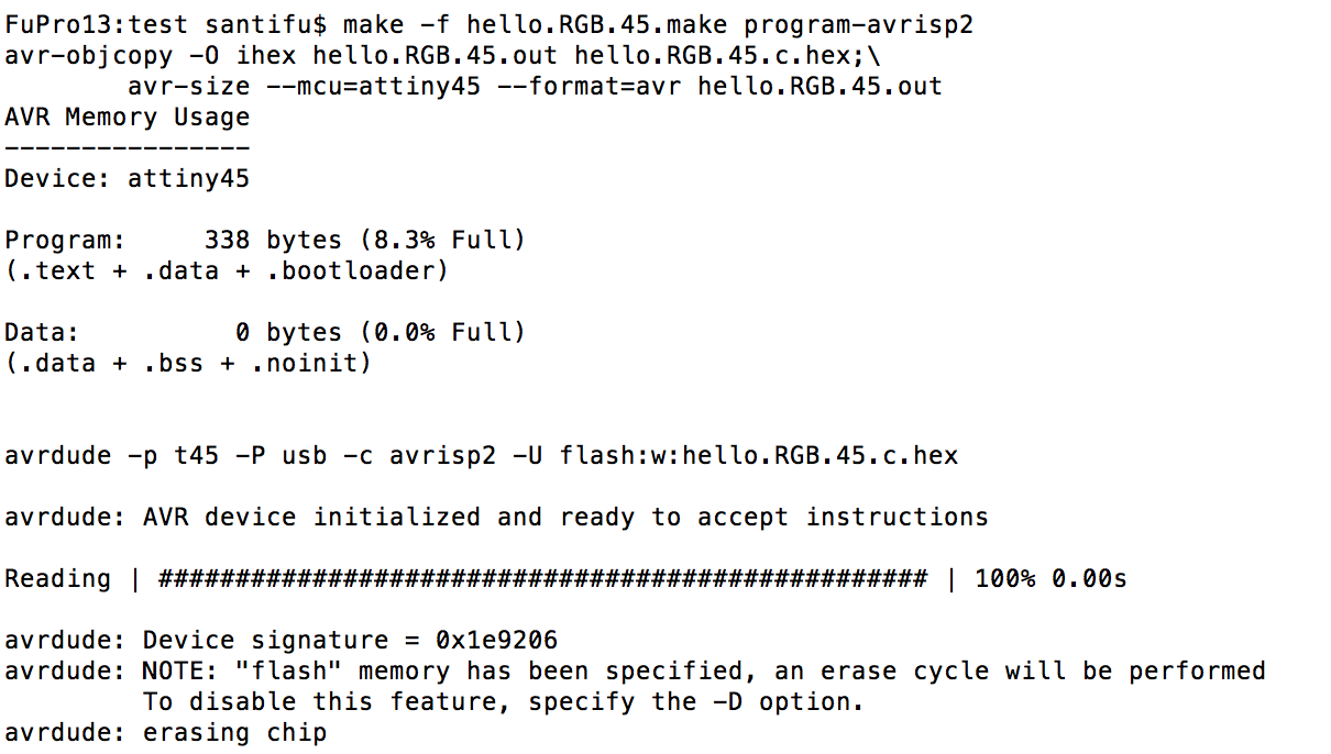
I opened the Terminal and i typed:
CD-> find the directory where these files are located
make-f hello.RGB.45.make program usbtiny
For programming I used the computer of my Instructor because I lost some drivers