Networking and Communications
MIT'S BRIEF Design and build a wired and/or wireless network connecting at least two processors
I built a network based on serial asynchronous communication
and I established a connection between the bridge board and two nodes.
The first step was to redesign the boards,then the milling process and soldering the components onto the boards
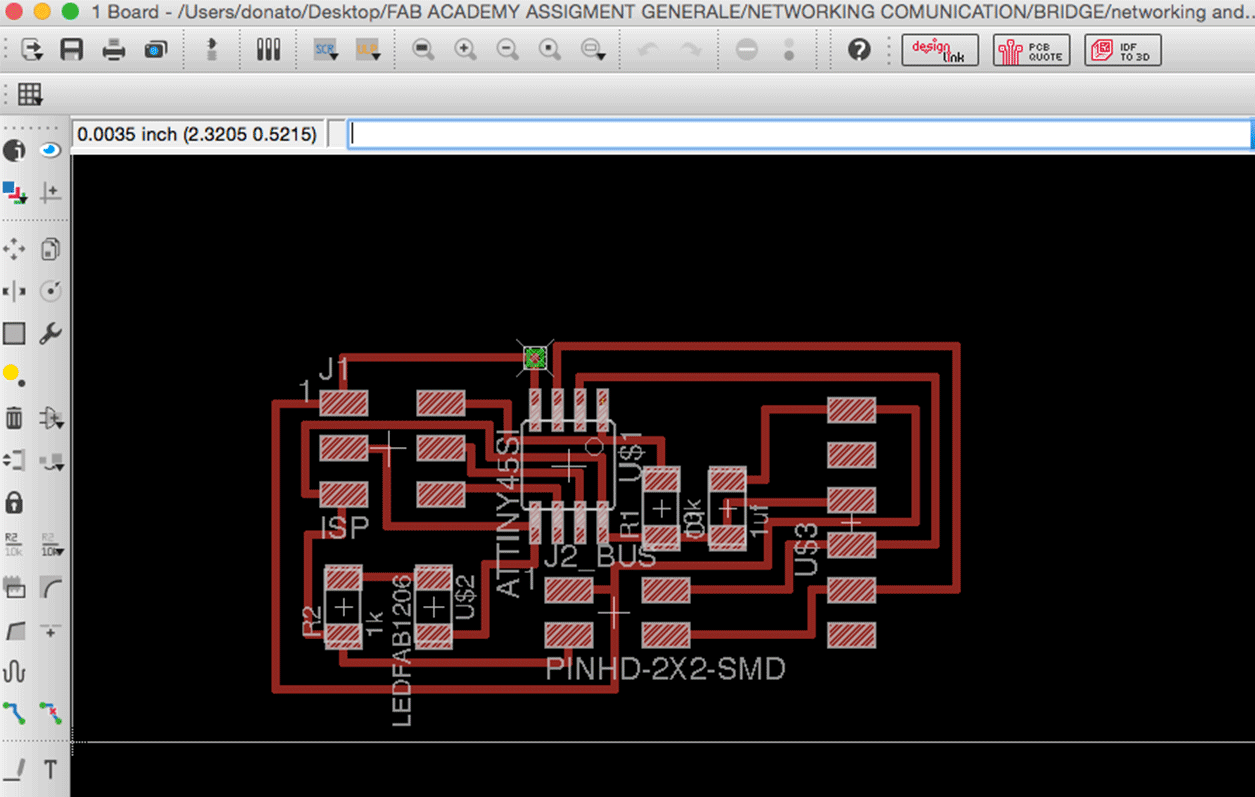
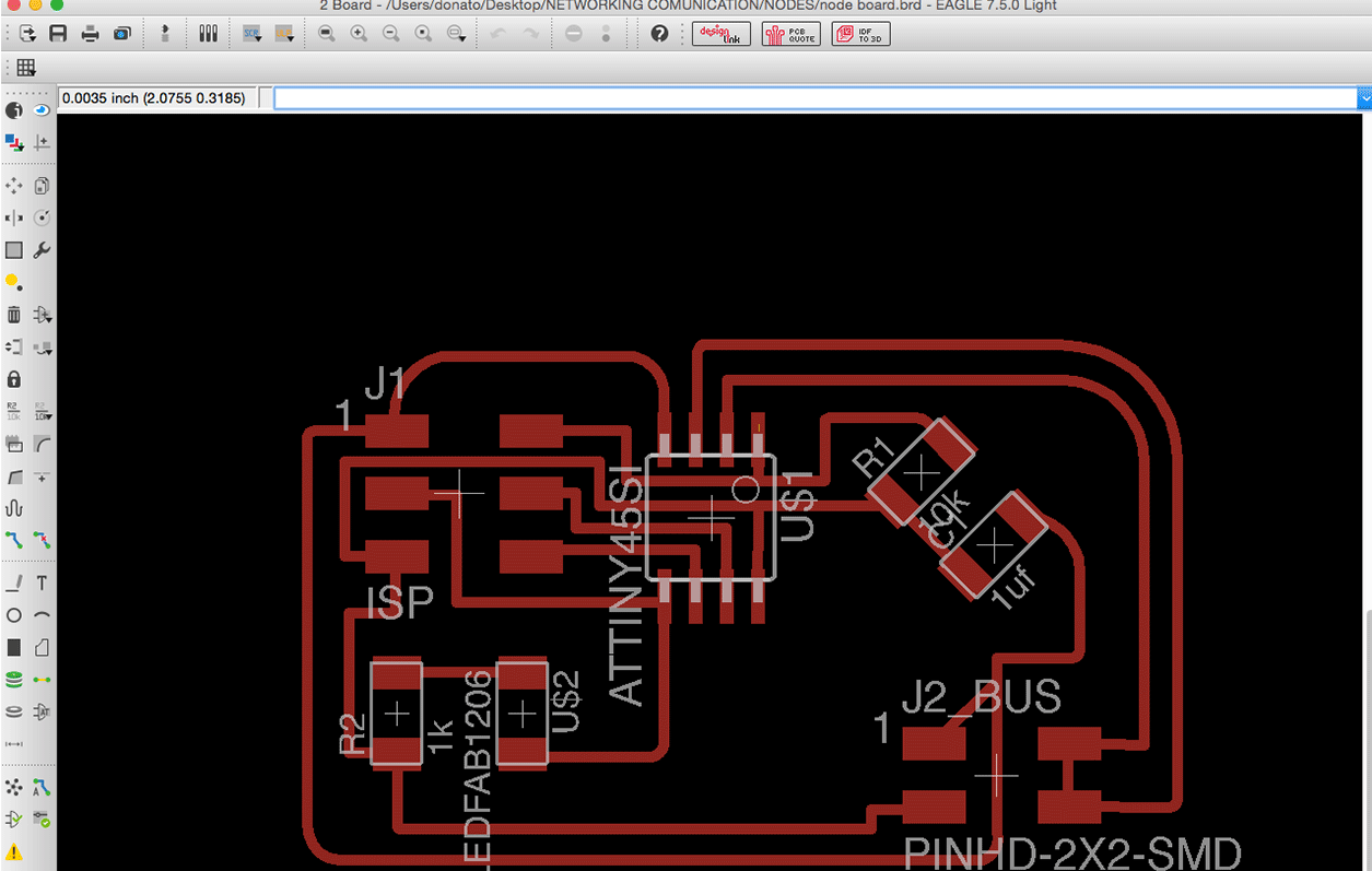
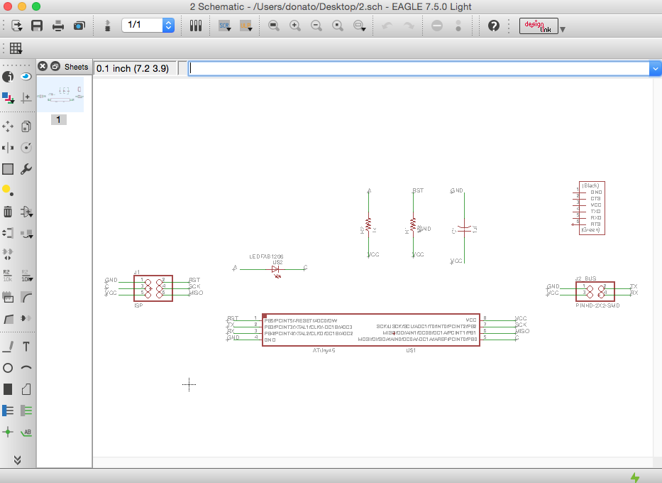
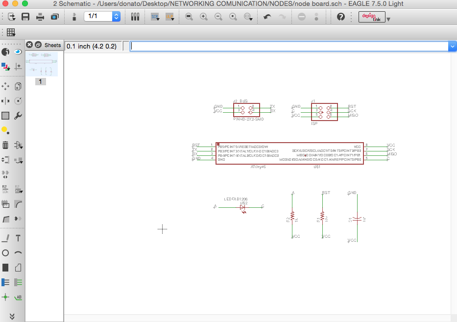
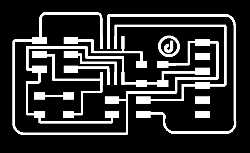
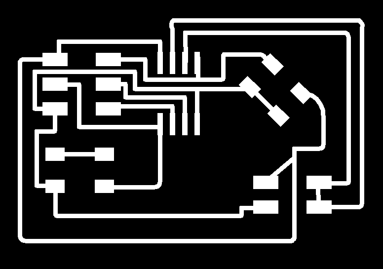
The image below shows the bridge board schematics and the node board schematic .
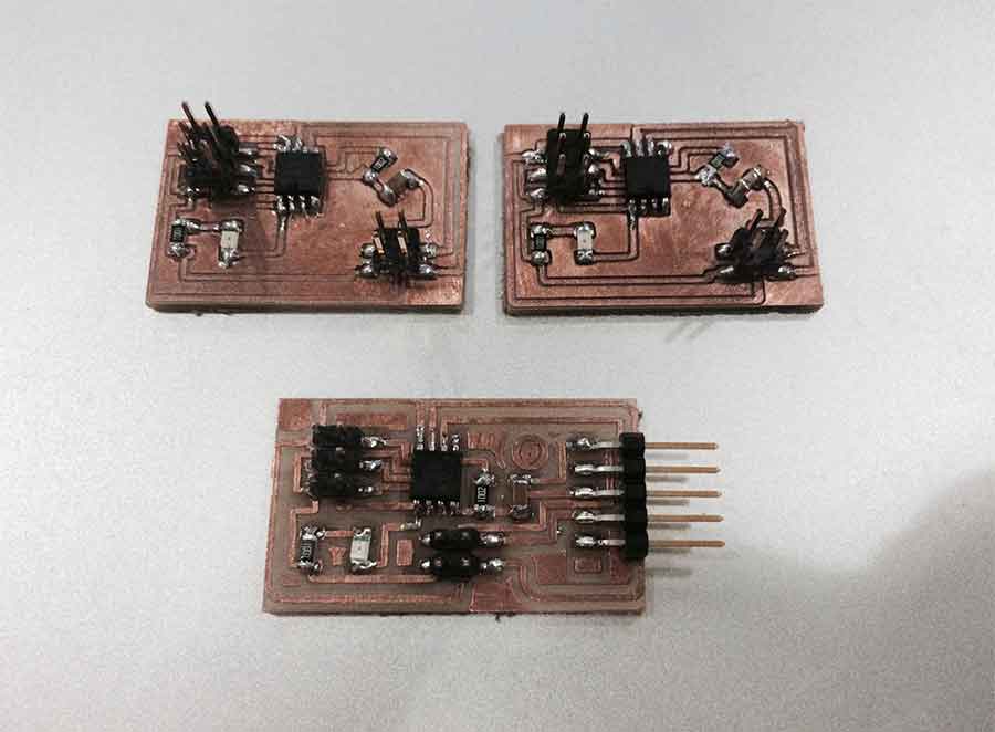
Soldering
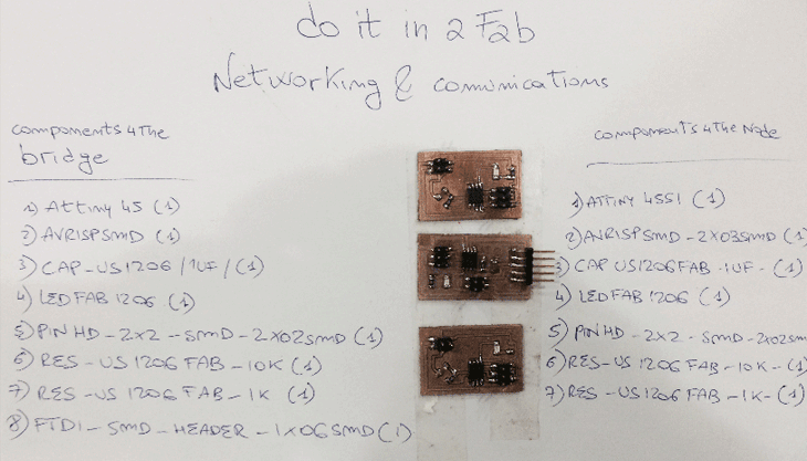
The list of components I used for the bridge
The components I used for the nodes
DOWNLOAD EAGLE FILES
Programming
Using the I2C networking protocol, data will be transferred without support from an external clock signal.Reading the I2C protocol I noticed that they are inherently suited to communications between two, and only two, devices.For further information regarding the I2C protocol have a look here.
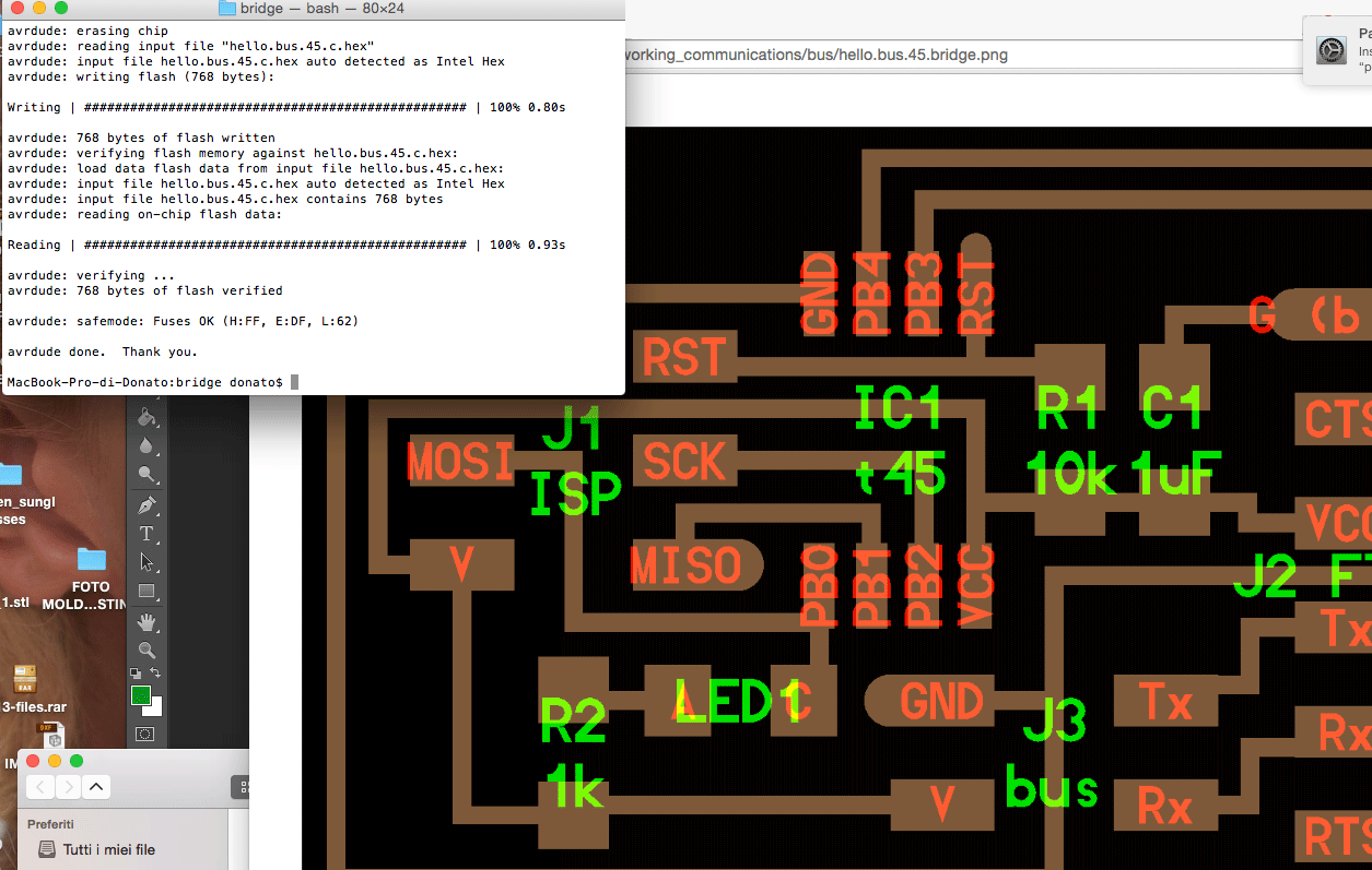
I uploaded the c code.I created a folder with the c file and the make file.On terminal I placed my folder with the c and the make file.On the c file i changed the define node_id '0' each node.
- For the first node: #define node_id '1'
- For the second node #define node_id '2'
Then I typed the sudo make-f hello.bus.45.make program-avrisp2 or ''sudo make -f hello.bus.45.make program-usbtiny''. For each board.
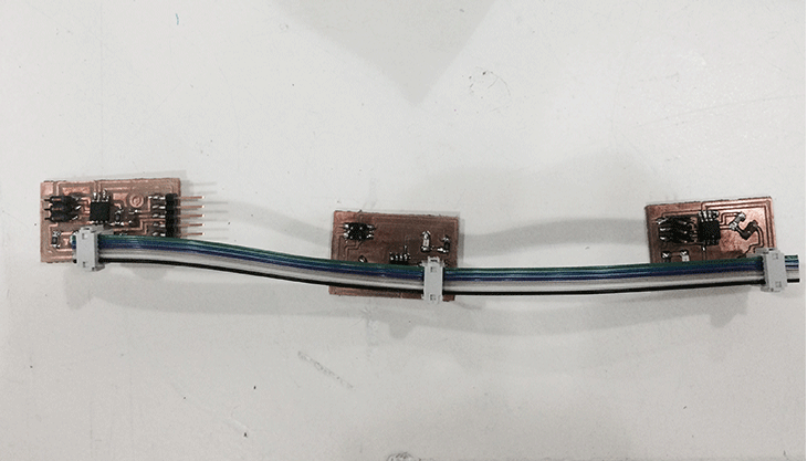
Connecting the board:
- Connect the bridge to the FTDI and on the other to the FabISP and programming with the c and make file that you change the node id to 0.
After that you connect the first node to the bridge with the network cable and the FabISP and program it with the c and make file that have the node id set as 1
Then connect the last node and follow the same process as node 1
Then I load the Arduino IDE and click on the serial monitor button.
On the serial monitor window just type 0,1 or 2 and press enter after the node you typed In order to let the reaction happen.