Mechanical Machine Design
MIT'S BRIEF
- Make a machine, including the end effector
- Build the passive parts and operate it manually
- Document the group project and your individual contribution
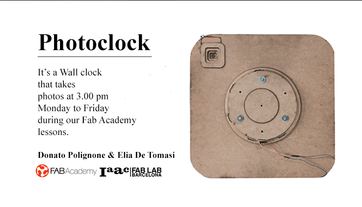
Photoclock
We decided to realize a very simple clock with a digital camera inside which captures decisive moments of everyday lesson of Fab Academy, from Monday to Friday at 15:00.
We decided to start by a planetary gear system which will be the basis for the mechanical part and input of the camera
3D Model
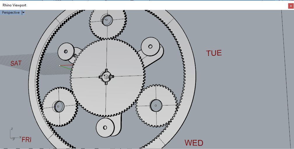
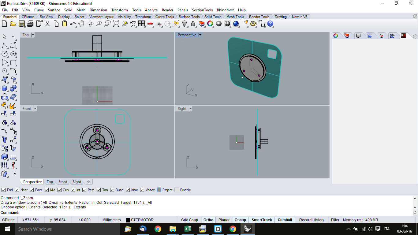 3D model of Photoclock Machine
Gear Generator
Elia has designed the model of Photoclock using Rhinoceros and caluculated the gear, looking for some software for generate Gear.
Donato has found many gear applications but all of them have a limit to generate a maximum of 200 teeth.
We tested also GearGenerator3.Patched.exe but the problem of the number of the teeth remain.
Teeth
External 168 teeth
Central 84 teeth
Small 42 teeth
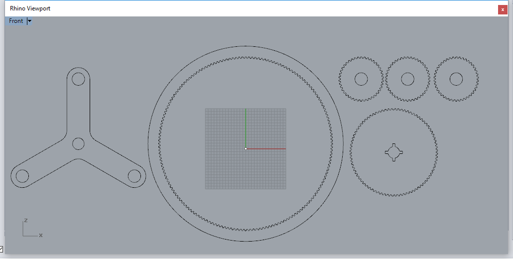
The External gear has 168 teeth like hours in a week. The Central gear has 84 teeth, the three small have 42 teeth each.
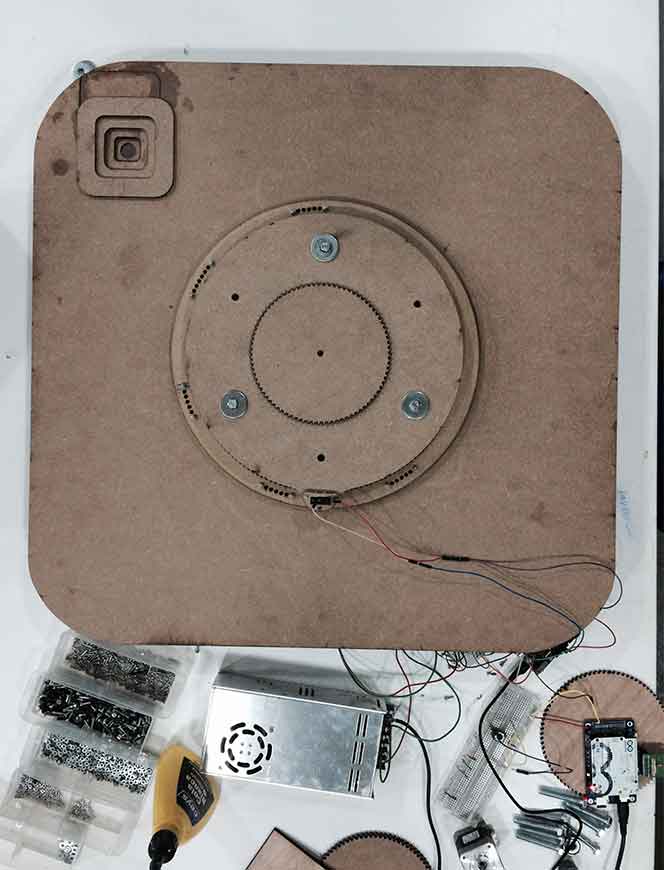
Step motor locking
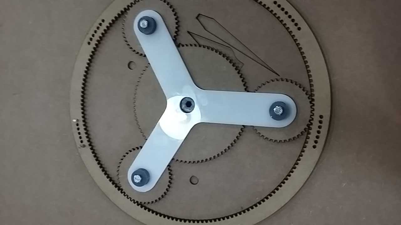
Donato had designed the Step motor locking. The step motor screw must not be longer than the thickness of the wood. We replicated the triangular shape of the planetary ruotanola of 60 °as not to interfere with the movement of the gear.
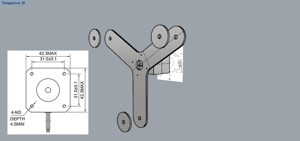
We placed the Step motor locking into the planetary system.
Mechanical Production
Donato Polignone has laser cutted the gear.
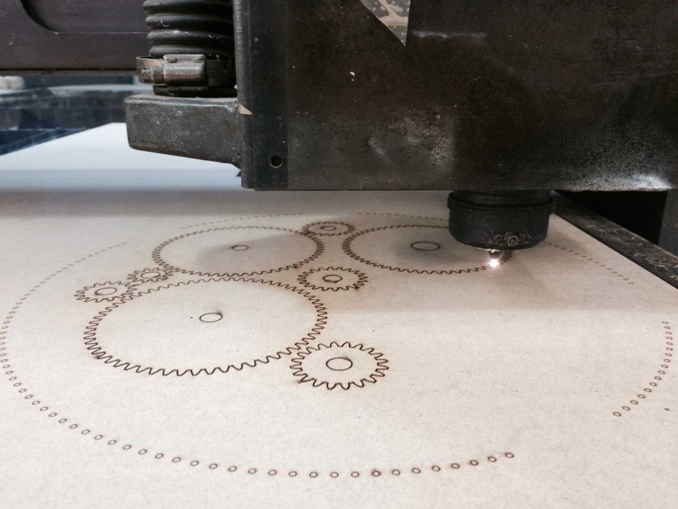
Laser cutter
Speed 10%
Power 360
Elia has 3D Printed the plastic bearing
3D Print Parameterslayer height 0.2
shell thickness 0.8
bottom/top thickness 0.8
fill density 35
print speed 60
support type: none
platform adhesion type: raft
The Trigger
Elia has designed and place an end stop with a wheel as a switch in correspondance of the bigger external crown. A sequence of screws, place in the correspondant holes will create a relief which activates the switch. Screws allow also to regulate and fix the height.
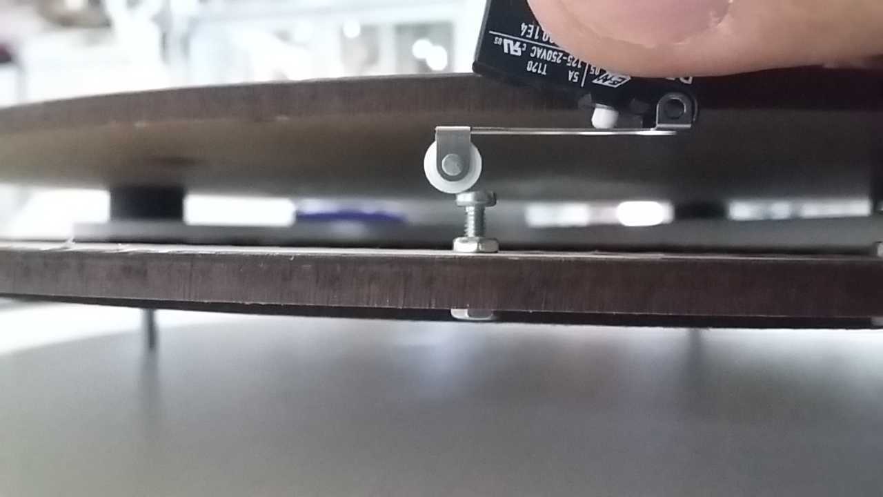 The switch created will be connected to the Arducam pin and will work as trigger to get the picture into the camera.
Assembly and move handly
Machine design
Assignment : automate your machine document, the group project and your individual contribution
The components
Let's check all the electronic components we need to complete the machine.The camera OV7670
Elia has decided to buy an entry level priced camera following many comments in internet. It was a mistake. Arduino has not enough resources to manage it and trying to use a camera without a dedicated processor it has been a nightmare. I think there is at least one way to use it without FIFO protocol, but I don't feel skilled enought to go into these fields right now.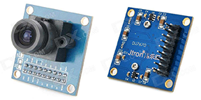
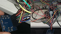
To manage so many wires into a project is also physically problematic.
Arducam REV C+
After long hours to trying to connect camera by wire my classmate Arnau gave me his own Arducam board...the 30 US dollars best spent in my life !!!
Arducam with a UC 260 Camera
Arducam Library
It is so easy to use it. You just need to install a library and all the examples are already working. You just need to select the right camera plugged into the board.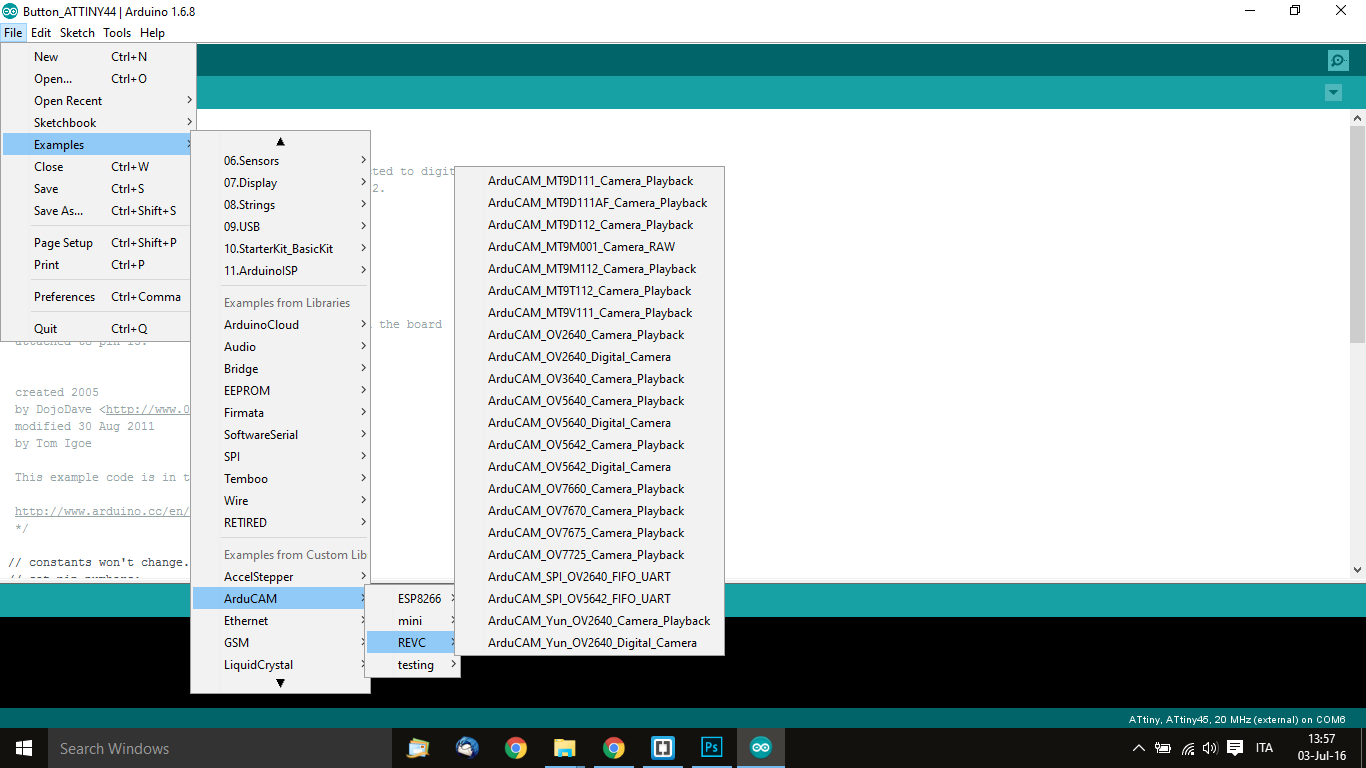
Select the right camera, our is UC260 Camera / Arducam Yun OV2640
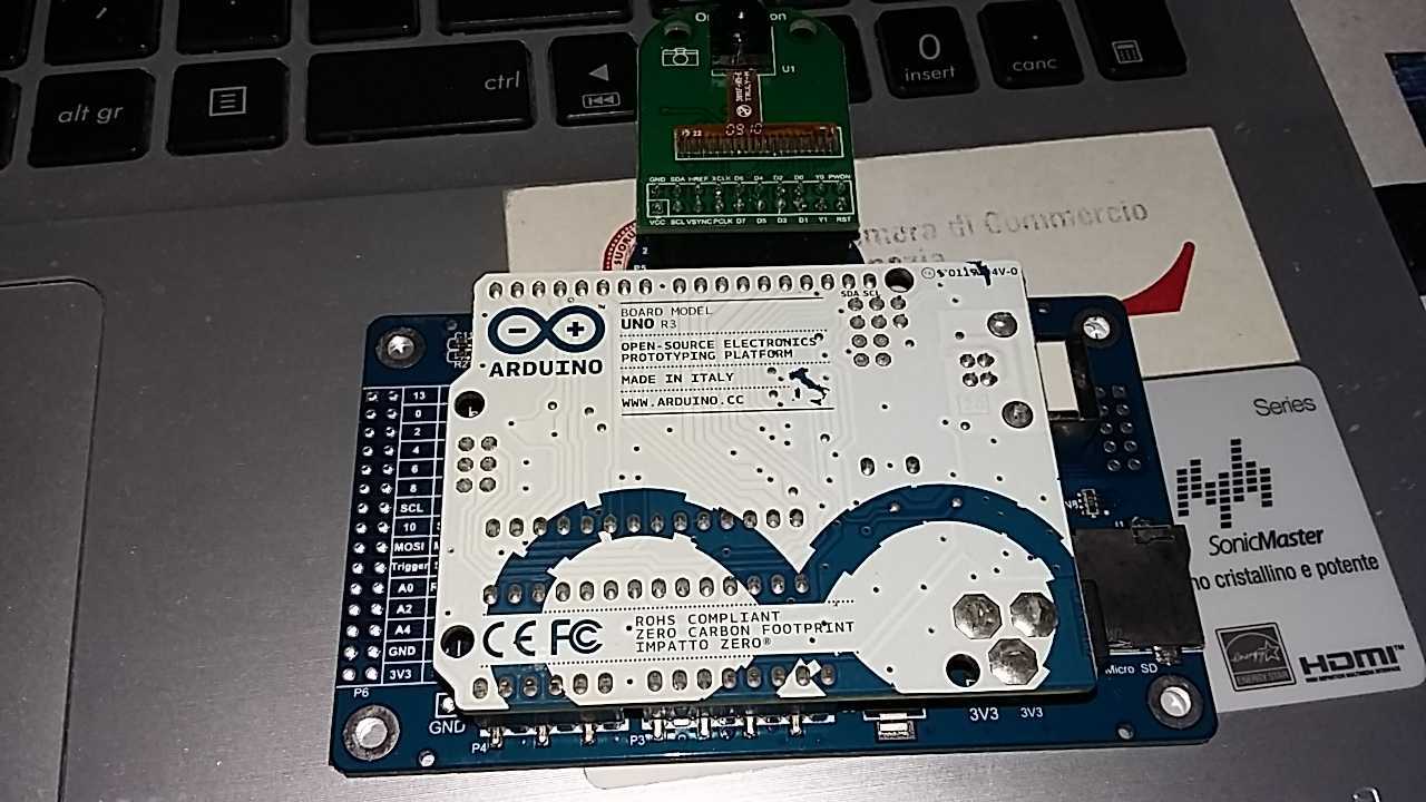
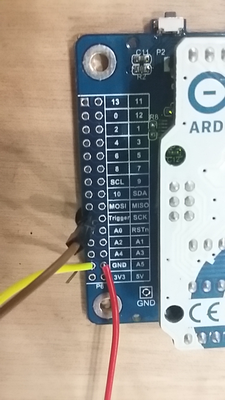
The boards connections
Firstly Arduino is busy for Arducam, Donato needs another board for programming the Stepper motor and the Switch/trigger input button. Input system bypass the on board Trigger
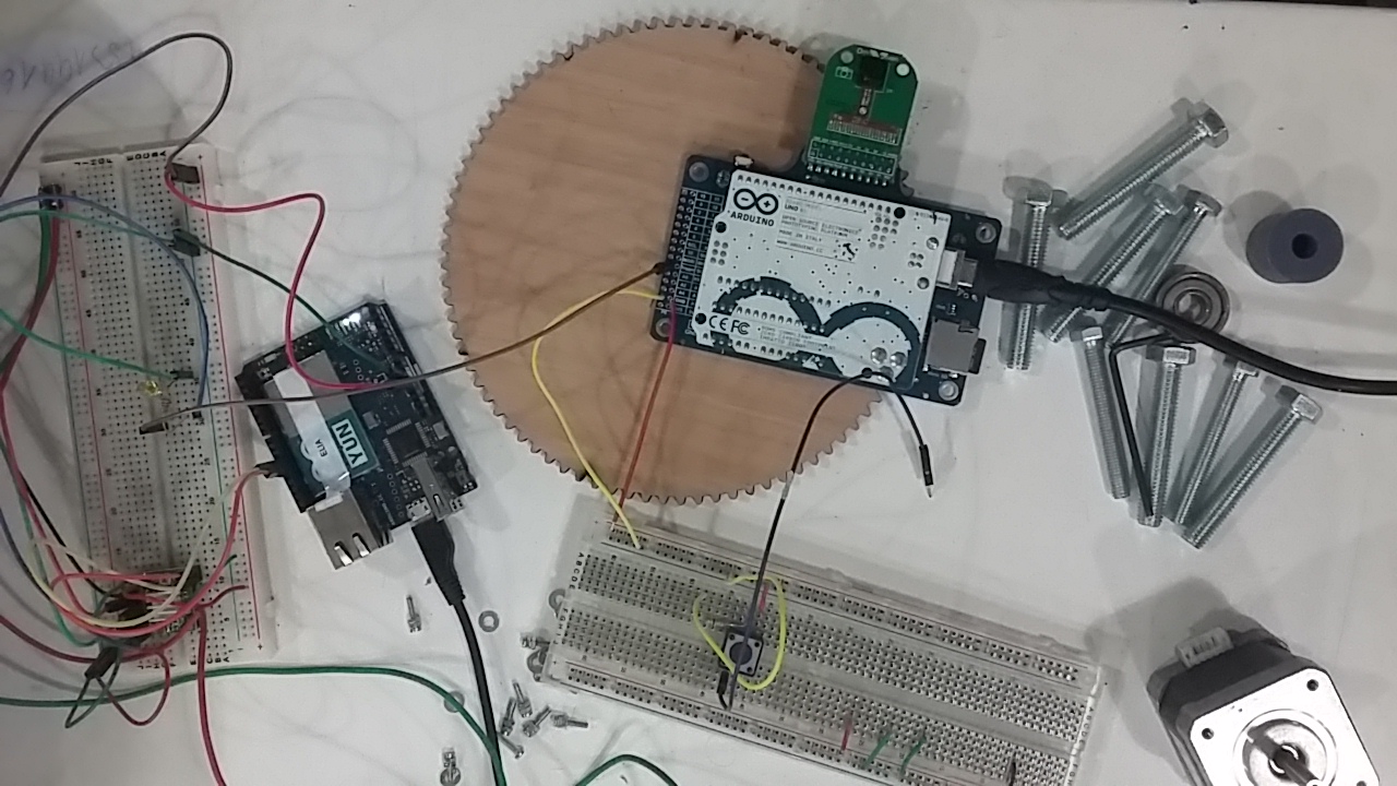
From Arduino UNO to Arducam Board by a trigger wire connections.
The code
Stepper motor does a single turn of 360°, 24 hours, and trigger will detect only 6 input in a day, one per hour from 15.00 to 19.00 We have two codes : one for Stepper motor and Trigger detection from switch button, and another code is the Arducam Code from library.
The result
DOWNLOAD FILES
DOWNLOAD FILES