
This week's assignment is about learning how to design Product and how to use the CNC machine to fabricate it. I wanted to make something useful and since in the room I'm staying here at Barcelona there isn't much space I wanted to make a Standing working station that I could easily disassemble and work in another place. This was also a good opportunity to learn Solidworks.
Since I've started FabAcademy I've been keen on learning more in depth the Design process and I wanted to use some of the things I learned in this Assignment. It all starts with a problem and a Idea...
I researched to see what there was already available in the market but everything I found wasn't modular,it was too big or simple. But it was a great starting point!


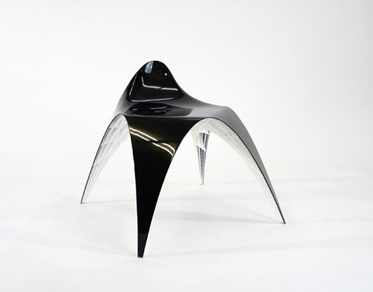
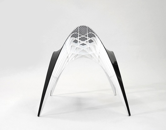
After research I started doing my own design and sketches, once again I looked for inspiration on the most unusual product design that may have nothing to do with the project but it has something that you relate with and you can use in your design.
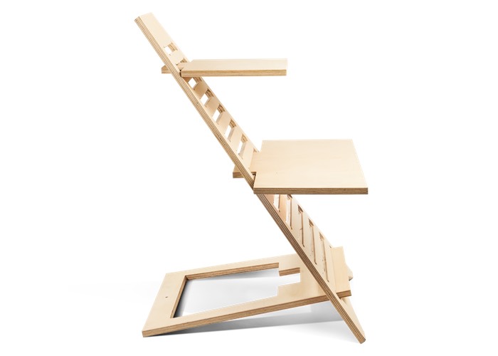
Thanks to Studio Geenen I got inspired by the lines of this chair and started sketching my project on Paper.
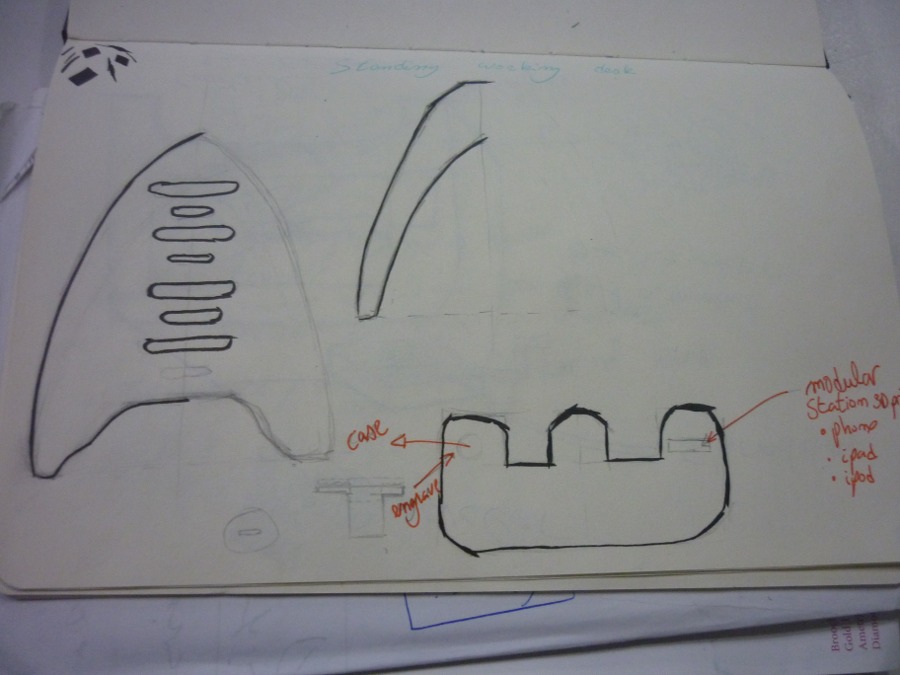
And then passed to Solidworks making some kind of skeleton frame sketch so I could position each part in the right position.
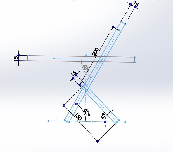
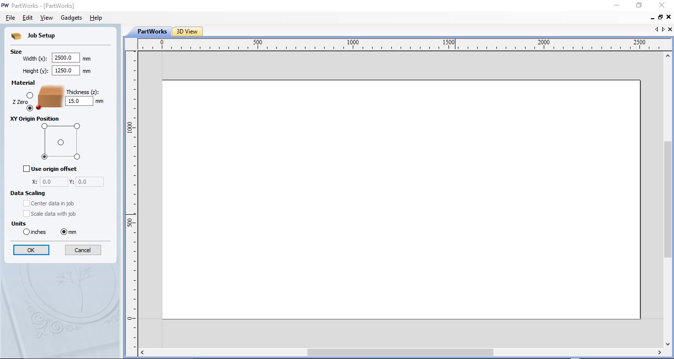
Creating some axis and planes as geometry references. Before modelling anything we must measure the sizes and thicknesses of the material we are going to use at least 3 times. Size of my OSB was 2500x1250mm and 14.8mm thick (it was supposed to be 15mm)
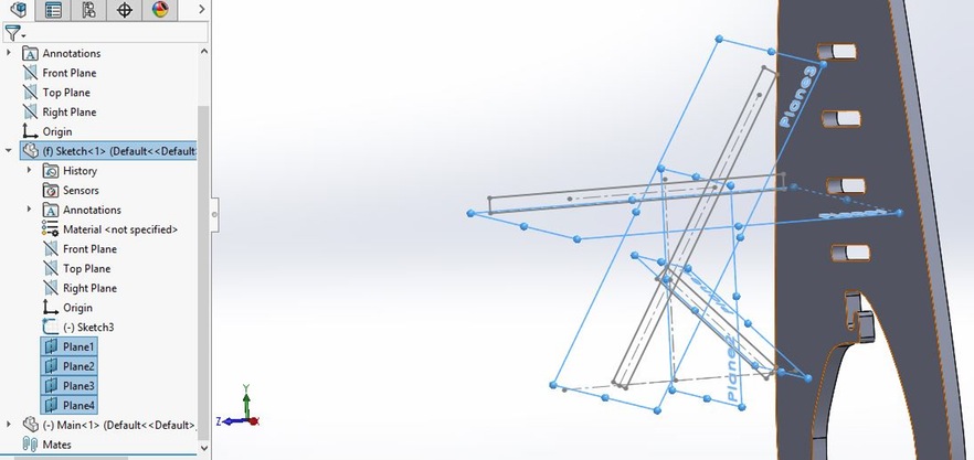
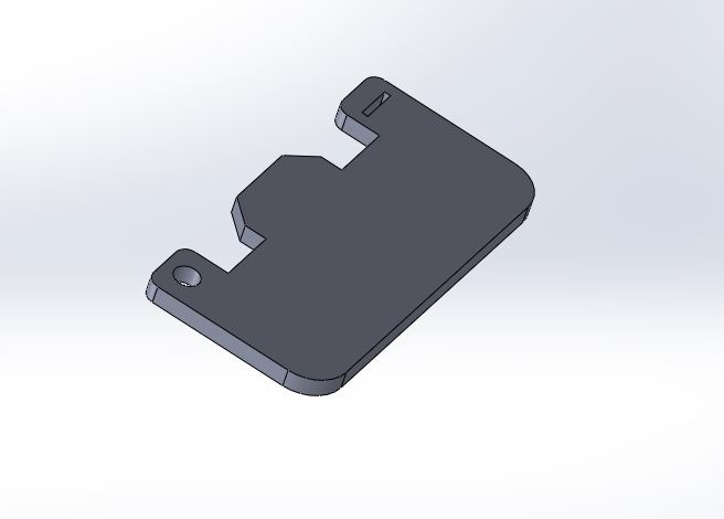
I started to build each part individually so in the end I could do an Assembly and check if everything will fit correctly.
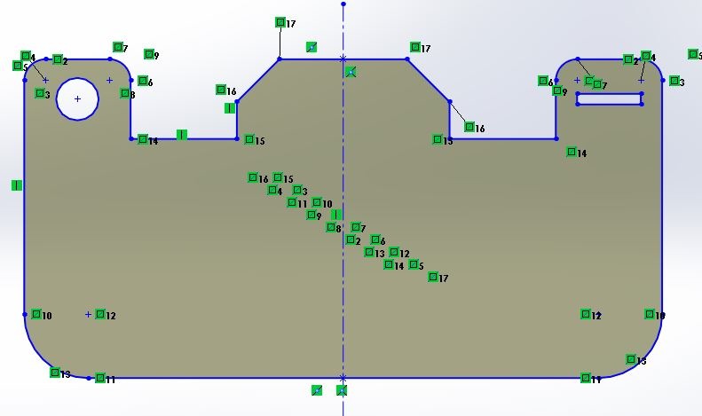
Making some sketches in solidworks and then extruding them to make the desired part.
After having a model that I was sufficiently satisfied I scaled its dxf file by 1/5 ratio since I modelled it for 15mm wood and wanted to cut in laser with a 3mm wood to create a small scale prototype.
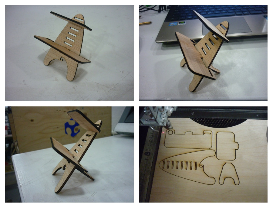
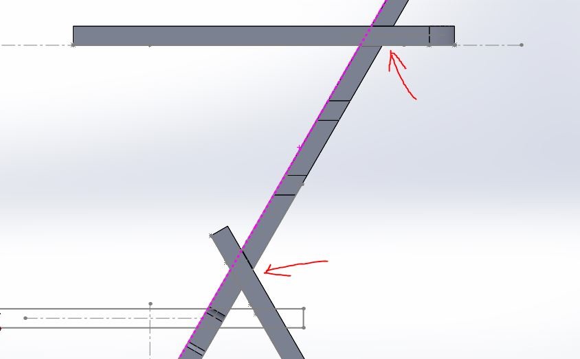
Forgot to calculate the needed angle for the working boards to be perfectly horizontal and the width of the prototype wasn't correct it was 3mm and for the perfect fit it should be 3.5mm. To change to the correct angle and check how it works in the assembly (SolidWorks Tip: use section view to see complicated areas and use "measure" in assembly between two faces to know the needed angle of cut).
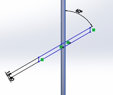
So I needed to remodel it and solve this problems, I started with the angle from the side view I created a rectangle and gave it the desired angle and made it coincident with the Side view right on the centre of the model. Then I created a new rectangle from the lowest and highest vertexes of the rectangle that intersected the model using this new rectangle as a new reference to make the "Cut extrusions" with the correct angle.
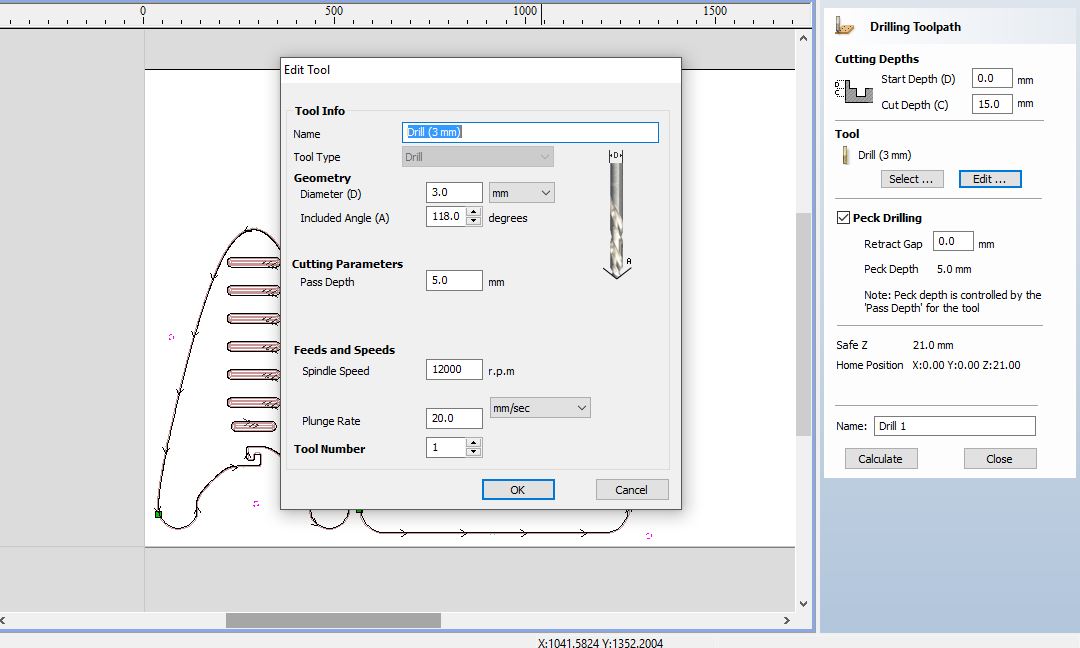
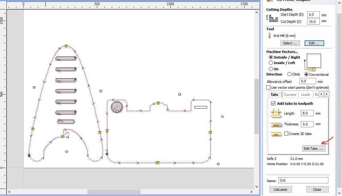
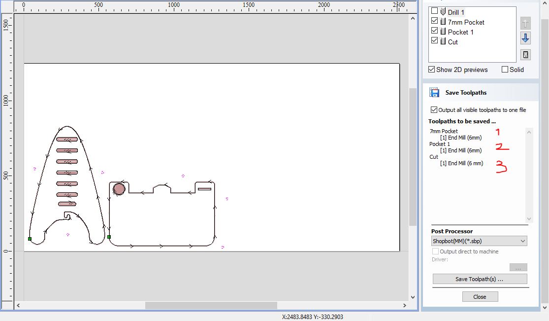
After solving most of the problems that I discovered through my small prototype it was time to cut the real deal. For that we have to create the g-code so the machine can interpret your design and cut it. So we use a CAM program to do this. The new Rhino Cam is one I really want to learn, as we use it a lot at OpoLab but there was a problem of Interpretation of g-code in the Shopbot so we had to use PartWorks. Never the less I´ll explain both processes.
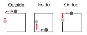
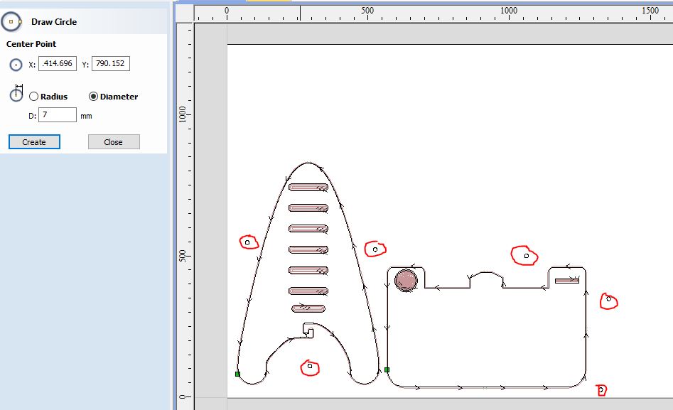 Types of toolpath. We have Profile, Pocket and Drilling toolpath. We use Profile toolpath to cut. We can make three different types of Profile toolpath of the line of our design: Outside the line, inside the line, or on top of the line. Pocket toolpath simply cuts pockets. We have two options with pocket toolpath: offset or raster, with the same final results. Finally, drill toolpath is just to make drills.
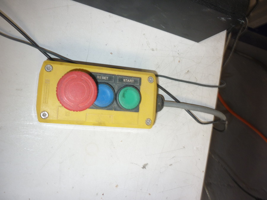
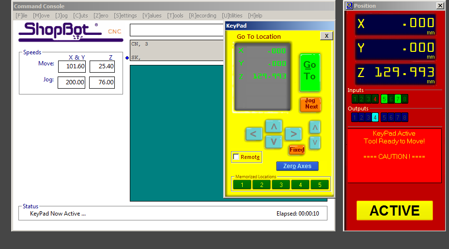
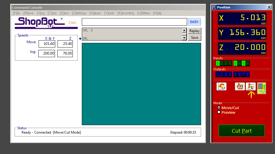
Now its time to cut in the Shopbot.
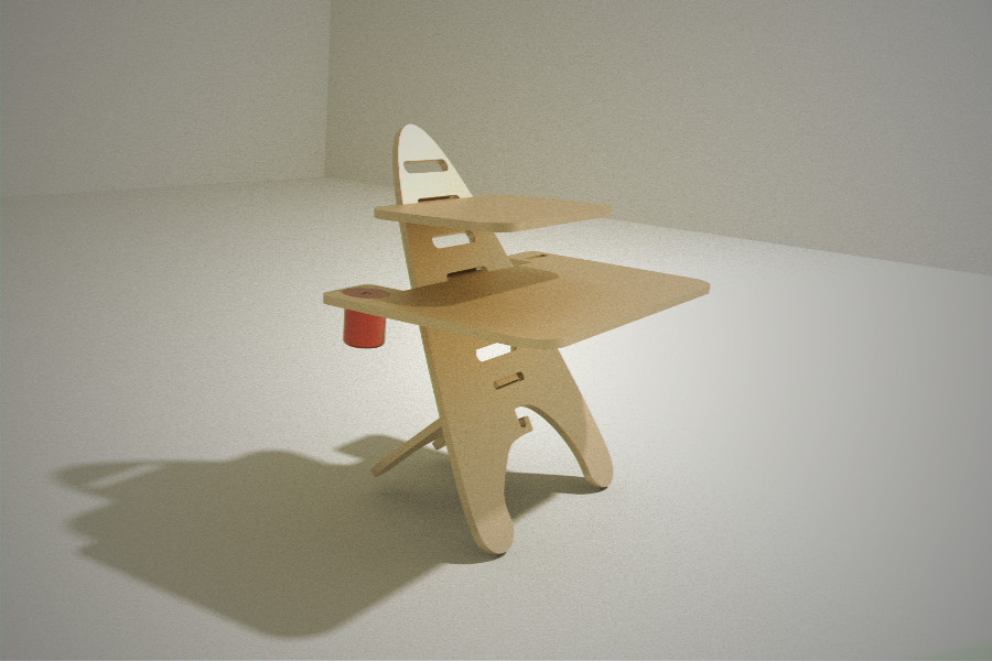
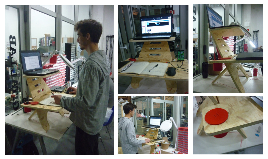
I had a blast with this project, even though I had a lot of problems and mistakes (It makes part of the process) in the end it all paid off!! This week gave me a great experience from the design to it's Manufacturing process and it is incredible how you can learn all of this in just a week. Of course there is much more to learn and a lot of space to improve. All though I could not completely solve the angle of the support piece, my colegue and friend Joe suggested I would use a cable to support and give a sturdier finish to the Working station. It worked very well and it looks nice! So far this is the end result:
As soon as I solve the angle problem I'll release the dxf Cutting files!
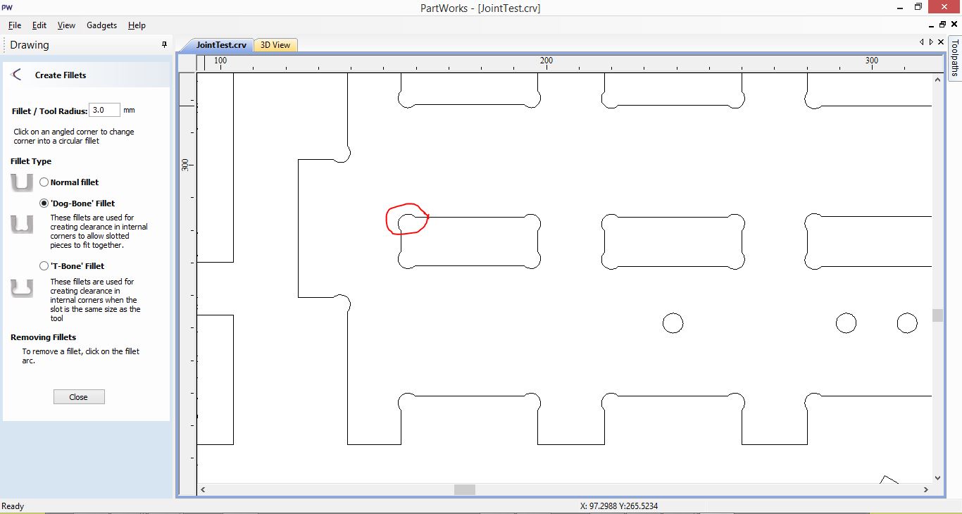
For those who want to work with Joint's and don't know were to start or which to use this 50 Types of Joints is a great source to look!
I know there is a lot of people who aren't sure which speed to use on the CNC, I am one of them, so I suggest you look into this wiki It has a lot of Information for every type of material and it is a great starting point. Feed Rates and Speeds Reference
There are many types of endmills it all depends on material and work to be done (cut, 3D roughing, drill, engrave, etc.). All of this changes the shape of the lower end, and the number and direction of the flutes.
Less than 2 flutes are good for chip clearing and more than 2 are better for finishing but aren't that good in clearing.

Depending on the direction of the flutes, there are upcuts and downcut bits. The first one, clear's chips from the kerf upwards and allow's faster feed rates. Downtcuts, pushes the chips down for a cleaner top suface, and require slower speeds rates.