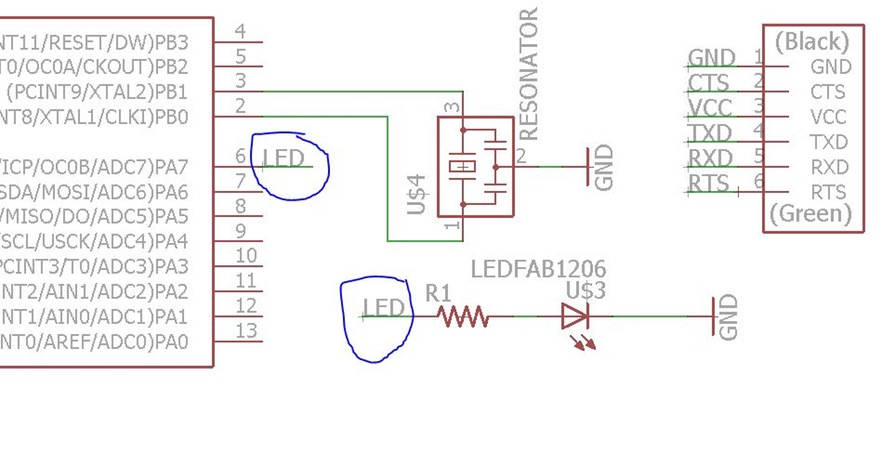
Redraw the Hello board adding at least a Button and LED
This week assignment is about learning how to design and fabricate a PCB from scratch using Eagle. The Art of Electronics is a great reference book for any component or Electrical circuit design. And a good source for DataSheet's of components is Octopart, you will need to visit the data sheet of certain components so you may know how to connect it or certain values. If you still not sure Google it!
Importante Electronics Concepts and Formulas
Concepts:
CURRENT is the (directed) flow of charge through a conductor.
VOLTAGE is the force that generates the current.
RESISTANCE is an opposition to current that is provided by a material, component, or circuit.
Formulas:
Ohms Law: V(Voltage)=I(Current) * R(Resistence)
Power: P = I^2 R = I V
Capacitance: C = Q/V, I = C dV/dt (used when working with capacitors)
Eagle CAD:
This was the first time I was using Eagle through the whole process from design to prototyping. And to learn this new tool I followed this two tutorials.
There is two ways to intereact with eagle:
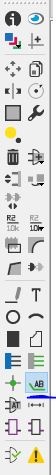
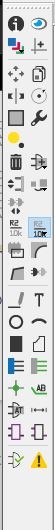
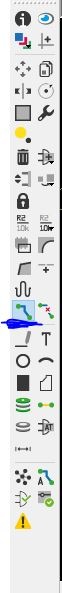
Graphical Icons Toolbar: You can use the icons in the left-hand toolbar, mouse over them to see what they do. (enabled by default).
Command Line: You can start typing a command at any point, then select the item in the schematic / board that you wish to interact with, see section on commands below.
Eagle command line - basic commands:
add = opens up the libraries so that you can add components in Schematic view always choose the 1206 components these are the ones that have 12mm x 6mm sized components
move = moves an item
net = makes a logical connection
junction = adds a junction
value = adds a value to components (i.e. ohm rating)
name = names a component
label = displays the name of a component in schematic view
copy = copies an existing component on the schematic.
route = used in Layout view, this tells you if you need to add a connection (follow yellow lines)
ERC = electronic rules check; this ensures your board will actually work (use in schematic view)
DRC = design rules check (in board view) - keep all the default settings (16 mil is fine); it should display a "no error" message in the bottom left hand corner of the screen
group = groups components in Layout view together; if you right-click, then you can choose Move: Group to move the grouping
rats = in board view, tells you if you have un connected wires
rip = deletes connections in layout
show = after typing this, select a component to see information about it displayed in the bottom left corner of the screen. Also, if you type show + [name of component] you can see that component highlighted. You can use this to see all the ground traces, for example.
text = allows you to add text to your board. You can also edit the exported .png file in The Gimp to give text and black and white line images. I recommend adding text in The Gimp.)
info = then click on text to get properties of the text
run bom = Will give you the Bill Of Materials of your board
Editing Schematic (Schematic design):
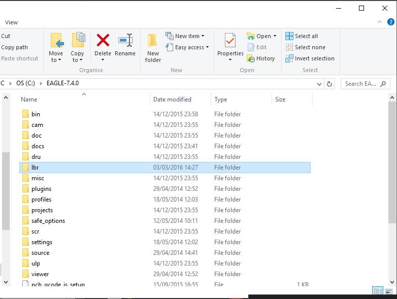
Before using Eagle we had to add the Fab Library of components that contains the Electrical parts that are presente in the Lab. We did it by Importing the library file to the Eagle Folder; Local Dik(:C); in the"Program Files"; Eagle; lbr(add fab.lbr)
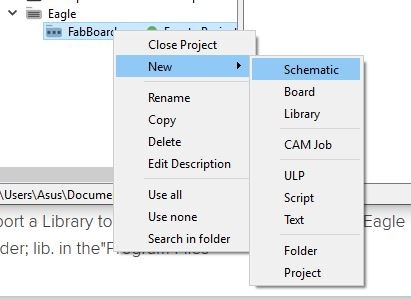
Now we are ready to start designing circuits in Eagle, we begin by Starting a New Project:
NOTE: I have renamed the libraries with a 01_ before the name of the library, so that they show up at the beginning of the "Add" list when adding new components.
Eagle Schematic Editor
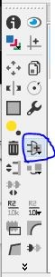
Start by adding all the components that you will need for your board:
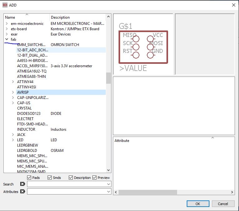
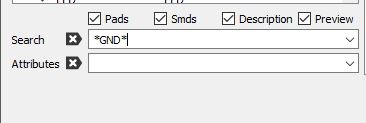
The Libraries list appears, look for the desired library you are going to choose the parts from. And then look for the part in the library, you can also use the search bar to look for the part. Wildcard - "*name of part*" this matches one or more characters
Two ways of connecting the Components:
Wire every connection
Label with the same name of the desired connections on both sides- make a wire and then give it a name and after that label it , this will make a virtual connection between the Components
Introduce the Value of the component
Eagle Board Editor:
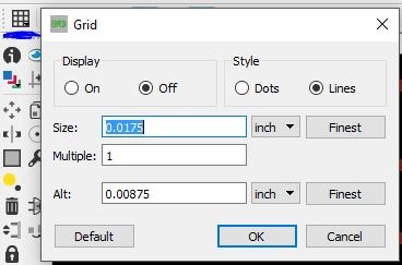
In the Board editor it is importante to change the grid settings.You can adjust the granularity of the grid, by clicking on the GRID icon. If you need finer control, hold down ALT on your keyboard to access the alternate grid, which is defined in the Alt box
Click in the "Generate/Switch to Board - This will open a new working area
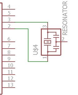
Use the "Show" command to know which connection in the "Board" mode represents in the "Schematic" Mode so you may organise it the best as possible
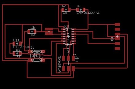
Make the connections between your components using the "Route" tool, follow the logic of your schematics, its a good idea to start from the "island" components you made in the schematic. Connect the yellow lines
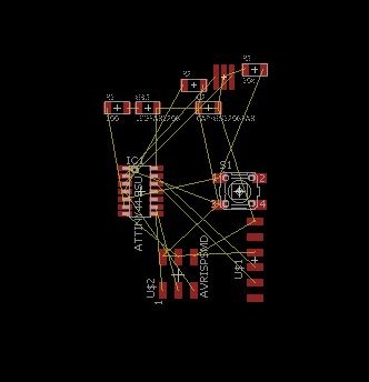
In the end your board should look something like this, resize and play around with the traces so it becomes as small as possible.
Check your board for milling clearance and Mistakes:
Ratsnest :
The first check is to make sure you’ve actually routed all of the nets in your schematic. To do this, hit the RATSNEST icon and then immediately check the bottom left status box. If you’ve routed everything, it should say “Ratsnest: Nothing to do!”
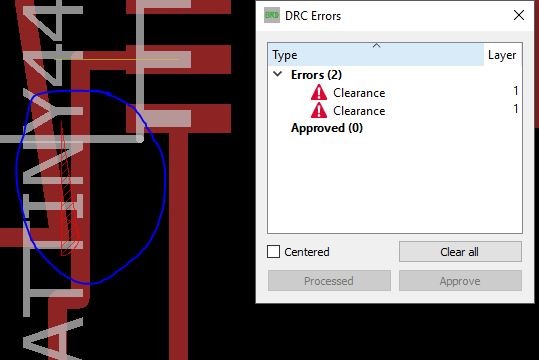
In the command line write "drc" and go to "Clearence" and write the diameter of the mill that you are going to use, this will check if the spaces between your traces are wide enough so the mill can pass without destroying a trace. In our case its a 1/64 inch (0.4mm) milling bit.
If there is a mistake a window will pop up with the location of the bad trace.
Tips and Tricks:
Name your Library to "01fab" so it appears at the beginning
Use 0ohm resistor to create bridges between complicated route connections
Exporting the board and prepare it on Gimp to be milled:
Remember: the Fabmodules cuts out the DARK and leaves white!
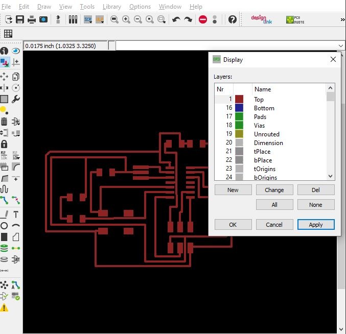
Go to Views" "Layers" and select only the top one.
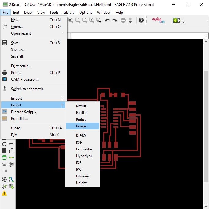
Then "Export" as image
Settings should be MONOCHROME and 500 DPI - this will export a image with white traces.
Then "Export" as image
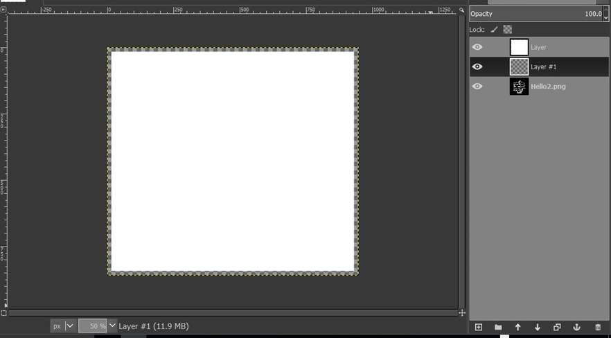
GIMP:
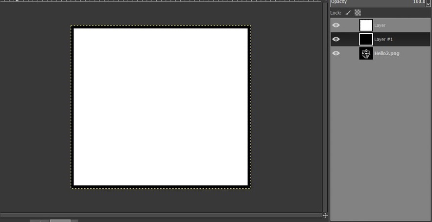
Create a new layer based on the size of your board and paint it White
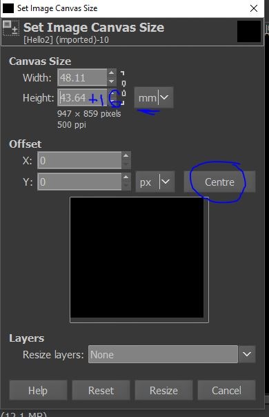
Resize canvas: Change the Units from "Pixels" to "mm" and add 1.6mm to both Width and Height. Dont forget to Center.
Create a new Layer and paint it Black, make sure it is below the White Layer
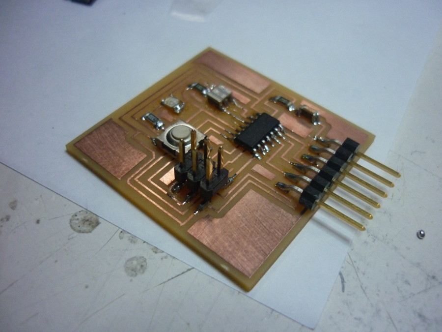
Milling and Soldering the Board
This is the Final result after milling and soldering.


 Now we are ready to start designing circuits in Eagle, we begin by Starting a New Project:

 In the end your board should look something like this, resize and play around with the traces so it becomes as small as possible.
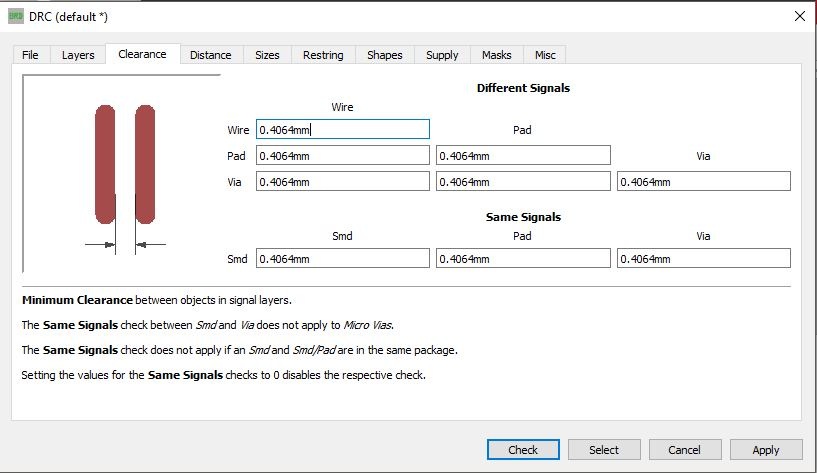 If there is a mistake a window will pop up with the location of the bad trace.