Design and 3D print an object (small, few cm) that could not be made subtractively
3D scan an object (and optionally print it) (extra credit: make your own scanner)
This week assignment is about creating a 3D model which cannot be made subtractively and print it.
3D Printing
Printing Materials:
This are some of the materials we can print with:
ABS
PLA
HIPS: Dissolvable in hot water
PVA: Dissolvable in hot water
Printing and Manufacturing Processes:
Here is a great resources on 3D printing from Stratasys it's a complete course but it's all divided into topics so it is easy to quickly consult.
Testing Your Printer:
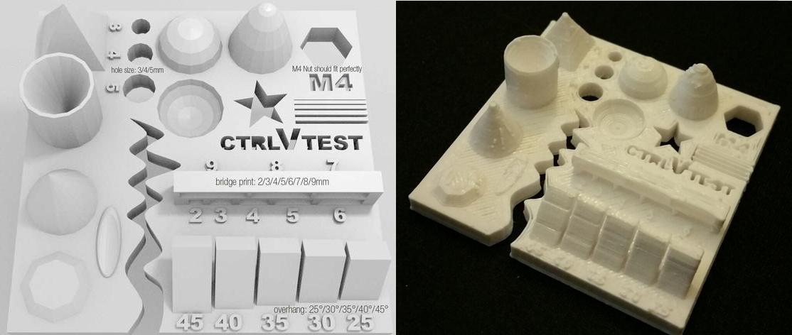
We've downloaded a standard test on Thingiverse and printed one. We discussed several points to look for when printing and how to solve some of the problems. This is the test list and what we can conclude from it:
Size: the object is 4 x 50 x 50 mm (baseplate) — measure with a caliper
Hole size: 3 holes (3/4/5mm) — measure with a caliper/drill
Nut size: M4 nut should fit perfectly — insert an M4 nut; it should need a little pressure
Fine details: pyramid, cone, all numbers — check if all things look nice and smooth
Rounded print: wave, half sphere — check if all things look nice and smooth (not every printer handles round things similar, e.g, it will be split in polygons) see here for more details
Minimum distance between walls: 0.1/0.2/0.3/0.4/0.5 mm — depending on your nozzle size and slicer settings you will get different results
Overhang: 25°/30°/35°/40°/45° — depending on printed material/cooling, these will not be as seen on the rendering provided
Flatness: all flat areas — these should be flat with no gaps
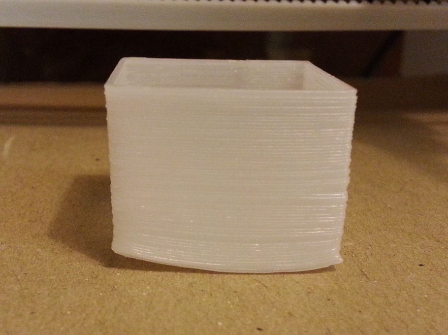
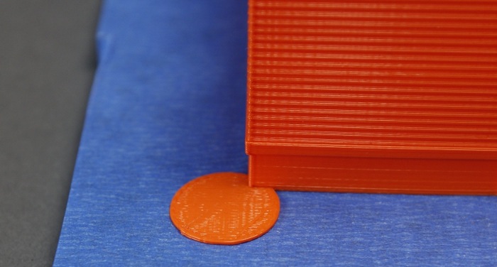
Warping:
When the corners of the print start to bend. Here are a couple of the methods to reduce the warping effect
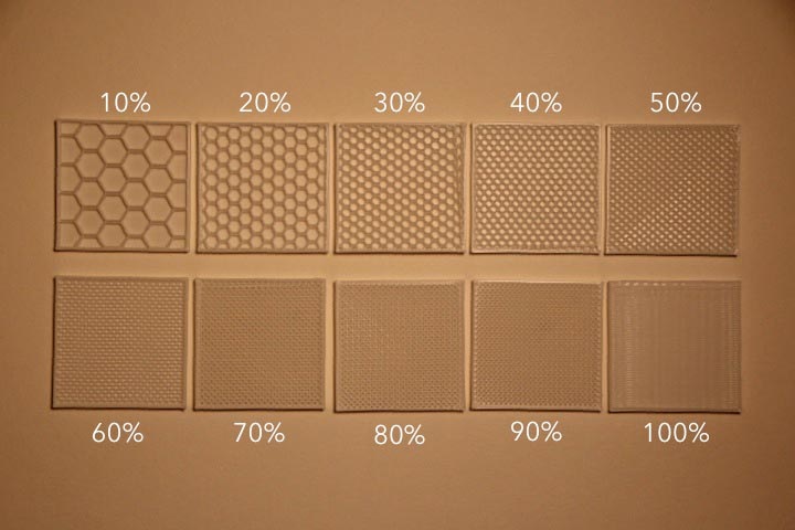
Reducing the in fill(different sizes and patterns) the less dense the model gets (Choose different sizes and patterns, the hexagonal ones take longer not recommended)
Reduce wall thickness
Create pads int he corners of your model
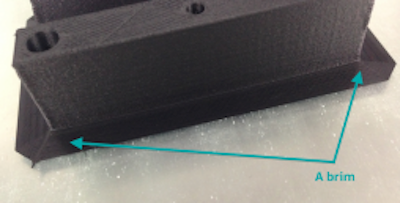
Brim - good to maintain the model on bed
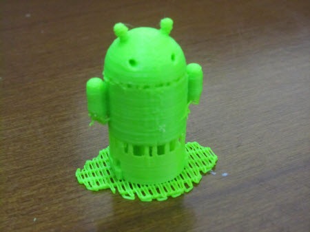
Raft - only good for model ta touch little the bed
Heat platform of printer
Hairspray is very good to stick models in the printers bed especially heated ones (take glass and spray, good for 5 prints)
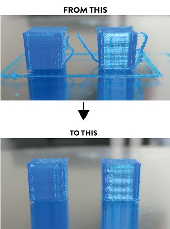
Retraction Fail:
If the top exmple is happening you have to change the retraction settings of your printer.
Software:
Before we print we must transfer our .STL files into a software that will slice it and turn it into a gcode. The Software we used was Cura but there are other good ones like Skeinforge or Slic3r
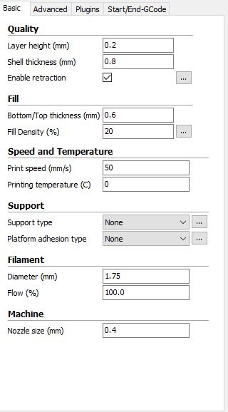
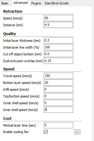
Cura Settings:
We were using Formbytes but each printer has its own definition so you have to tweek and test the settings from your printer.
Layer height - 0.2mm best, 0.3mm and increase temperature for good mechanical properties.
Shell thickness - 2-3mm.
Bottom top - 0.6mm.
Infill - at least 20%.
Print speed - the lower the better definition.
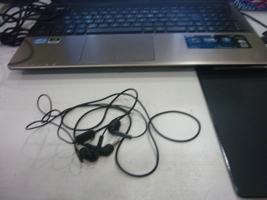
After all of this changes I was ready to try and 3D print something I needed, something that would help me organise my headphones.
Voronoi Dome
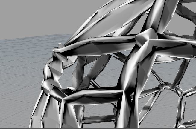
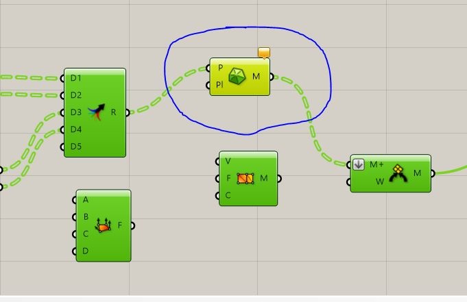
I've always been fascinated with organic Structures and wanted to have a go on creating such a model using Rhino+Grasshopper. After looking at a couple of tutorial in the internet I gave it a shot, at first I was having a wierd problem on how the meshes were being created.
After retraicing my steps I found out the problem was the points created wasn't being distributed as it should and I couldn't find a solution. After a couple of hours trying to get a solution, Joe suggested me to use "Delaunay Mesh" instead of the "Construct mesh" which creates the mesh from a group of points.It
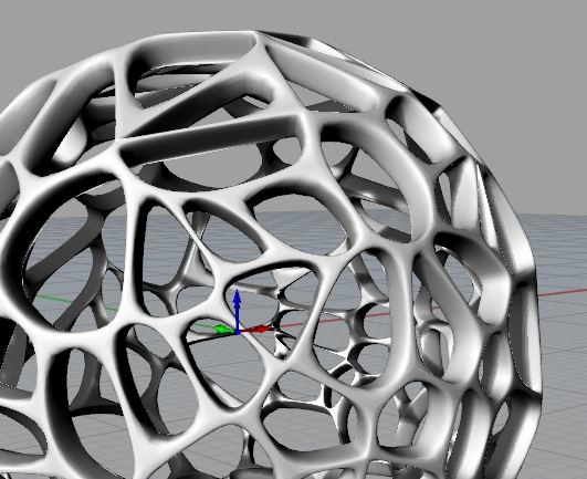
It Solved It!!
I just needed to print it and see it would do a good print! But to be able to print I had to thicken the walls of the dome, because they were to thin and in Blender using the "3D Printing Test" it was giving me several errors.
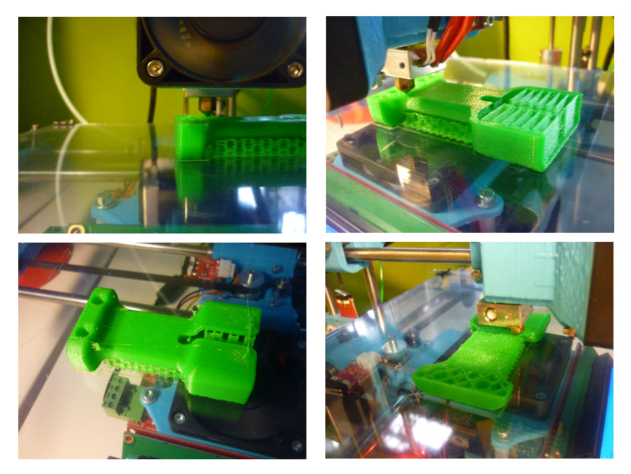
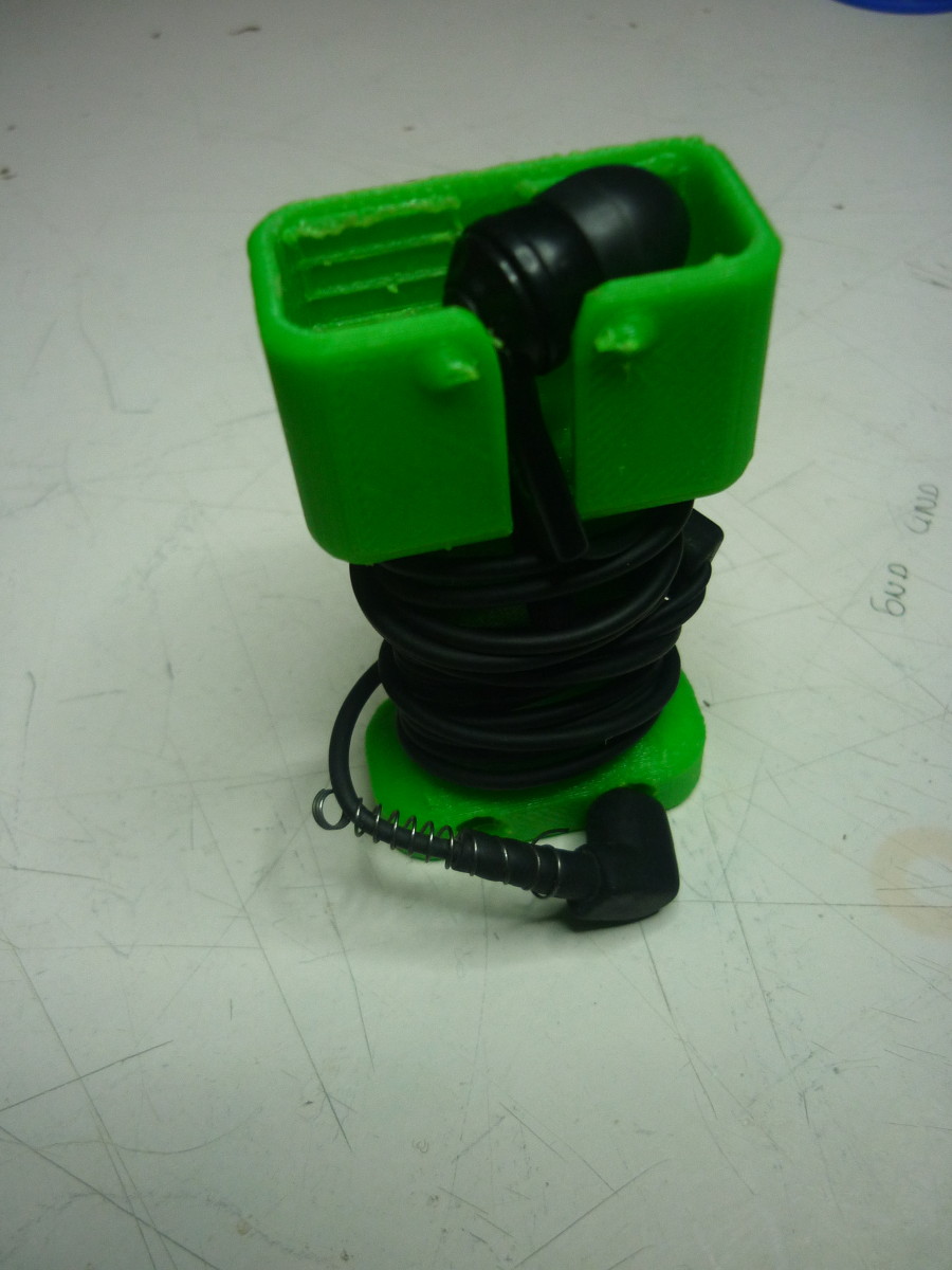
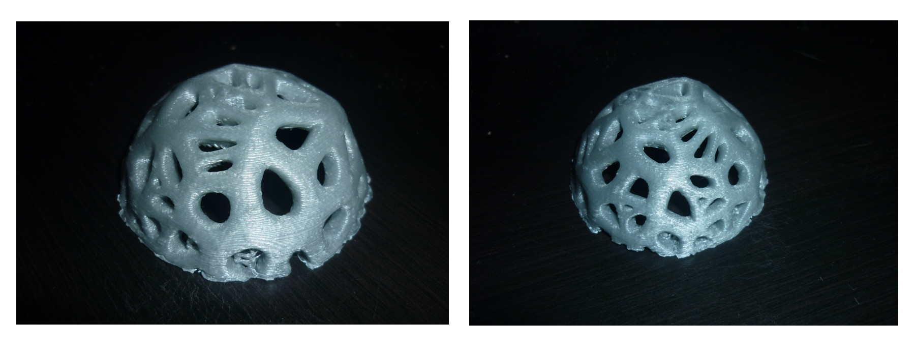
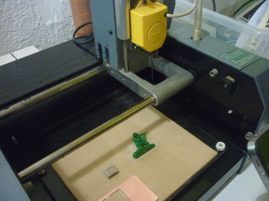
Printing results:
Scanning:
So for the scanning assignement I wanted to test as many differente methods of scanning as possible so I have a feeling to the possibilities of each method.
Software used:
Skanect
Dr.Picza
Fabscan100
Kinect 360:
After Installing the Drivers And Software plug your kinect
Prepare Model to be scan have as much background reference points
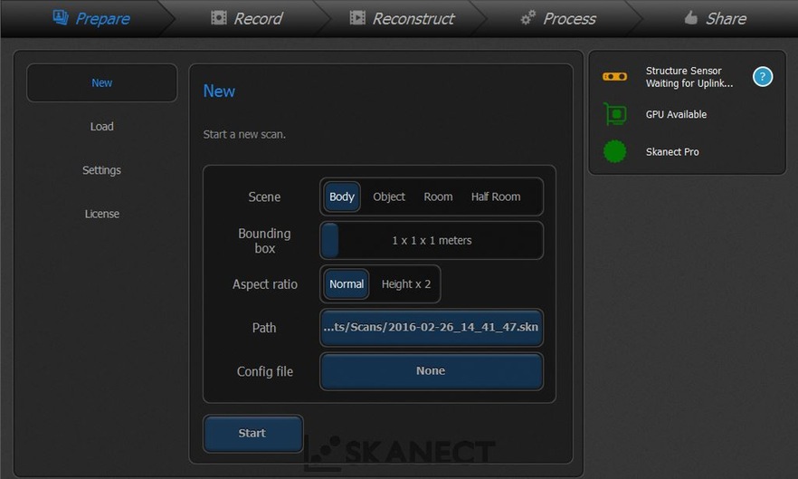
In the Skanet "Prepare" to scan, depending on the type of object being scanned "Object/Body " Choose the Scene, Bounding box is the area of the box to be scanned(better be a bit bigger than the actual size of the object
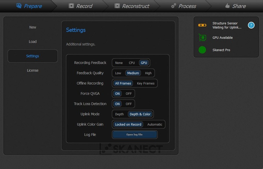
In "Settings" you can change the "recording feedback" if you have more processing power in CPU(Processor) than in your GPU (Graphics card), In "FeedBack" is recommended in Medium but if you want a better quality choose High but know that the end model will be heavier and it will take more processing out of your computer
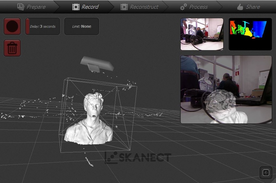
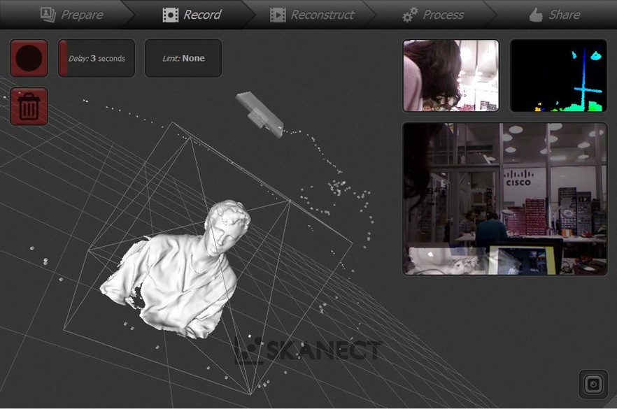
Record: Hit record and start Scanning the object
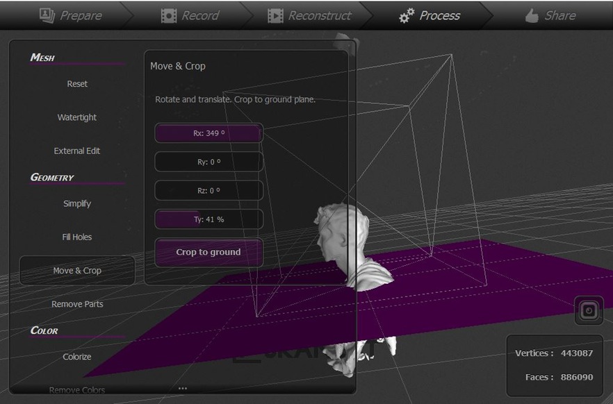
When finished head to the "Process", here you can do some basic changes to your model.
"Remove Parts" - you can remove meshes that are orbiting your model.
"Move and Crop" - you can move your model and move the cutting platform so you can crop and cut the object.
"Fill Holes" + "Watertight" will patch any open spot in your mesh and make it ready for 3D printing.
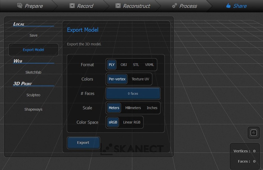
Export your file, there are several options of files you can export to.
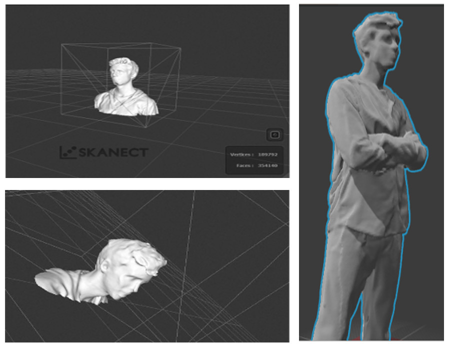
Scanning Results:
Dr.Picza:
Change the head of the Modela from the melling one for the Scanning head.
Prepare Model to be scan use some kind of adhesive material.
Download and install the "Dr.Picza" Software(official Roland Software)
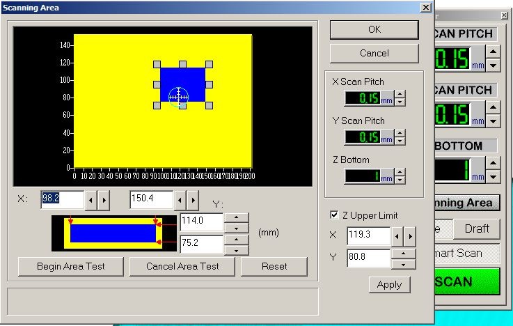
Tell the Modela the area of the bed that requires scanning, make it as close as possible to the boundariees of the object. Use the visual representation of the scanning area and the drag handles to adjust the size of the area.(If you double click on handle it will teste that spot)
Tick Z upper Limit it will decrease almost 15s per cycle
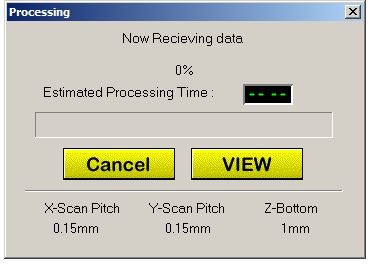
Click Scan. It will take several hours depending on the size of the model and the scan pitch, the lower it is the better the detail but it takes longer.
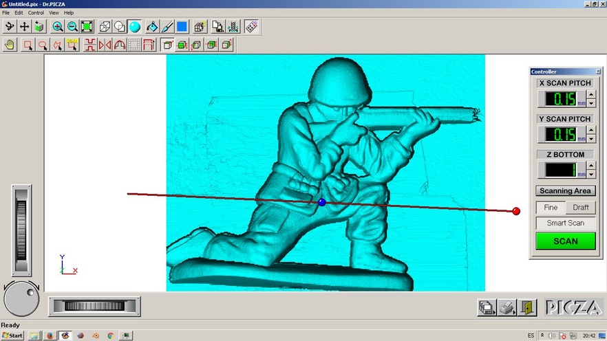
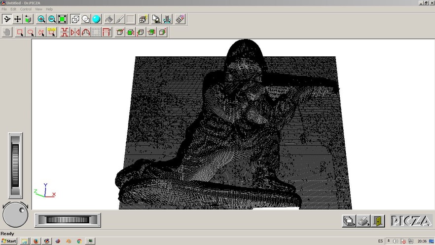
In the end you will have a very detailed 3D model of your object.
123D Catch:
A App from autodesk that with 20 pictures creates a pretty good 3D Scan of a object. I didn't try it here at the FabAcademy because I already had during my learning in OpoLab but I leaver here a note so people with out the possibility to use one of the Scanners mentioned before can still try it.
Side Projects:
Building a Scanner:
So after using several techniques on scanning we encountered the same problem every time we had to many wires or us going around the model with the scanner wasn’t practical. So I resolved to make a Scanning system.
Continuing the recycling theme I've been having ever since I've came to Fab Lab Barcelona I went looking for something I could use as a bases to build the scanner knowing I wouldn't have much time.
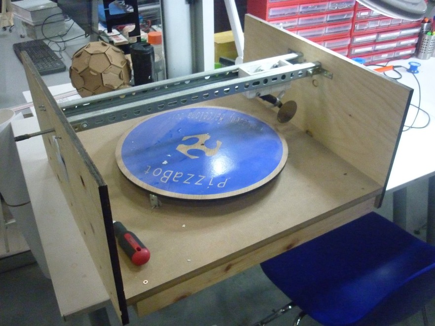
Ferdi suggested me to use PizzaBot, last years project and with his help started this side project.
I mainly used the turning base and gears from this project as a starting point.
Bill of Materials
Base: PizzaBot 2015
Use the Vector design from Inkscape and Export to 3D modelling Program
Extrude and create a 3D model based on the Designs
Motor Driver
Stepper Motor Nema 17
16mm Straight laser pointer or Kinect 360
Arduino UNOr
SShield For stepper motor Driver
12V Power Supply
Procedure
I'll give a overview of the steps I've taken on making this recycled scanner:
Disassembled unwanted parts from the PizzaBot
Create a turning table by Connecting the Step Motor, Driver and Power Supply to the Arduino.
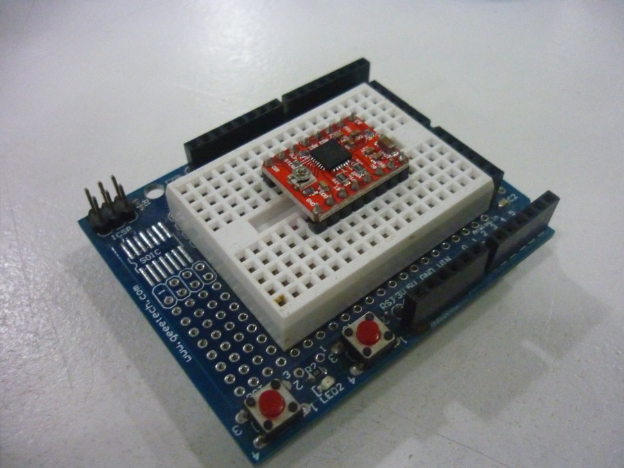
Mount the Motor Driver in the shield and connect it to the arduino.
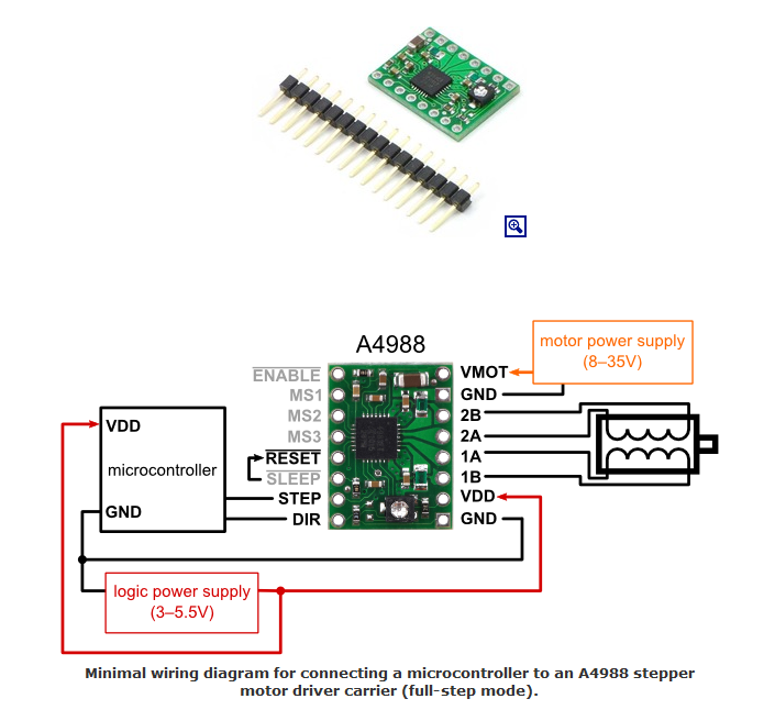
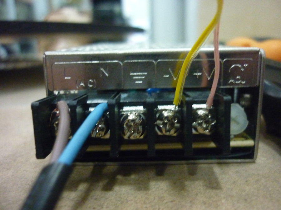
For the Motor Driver Connections I used this diagram as a guide.
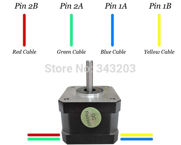
To know the Nema 17 Connections.
Before connecting the power supply test it's Voltage with a multimeter, so you know it doesn't give to much or to little power.
Arduino Code:
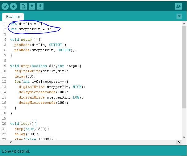
For the Arduino code, to control the speed and direction of the Stepper motor I based my code on the Example that SparkFun Elecronics gives from LusoRobotica a Portuguese Robotics Blog (who knew!?). You can see it here
Change Pin Output to the Arduino pins you've connected the Dir and Stepper pins from the Driver motor.
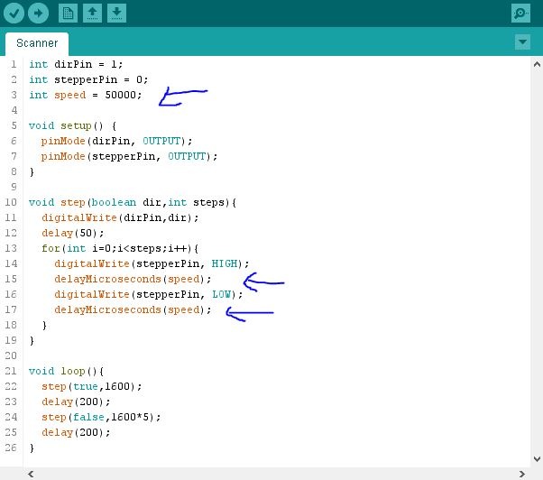
Make a speed variable "int speed = 80;" so it is easier to change the delay of the stepper motor.
Change the "delayMilliseconds" to "delay" and change its value to the "speed" variable created in last step. This will make it delay in Seconds which makes the stepper motor to be slower.
Scanning Software
Fabscan100
If you have a MAc or Linux this is the best place to get the FabScan100 software.
If you are using a Windows computer it is advised to use the Processing Processing Fabscan or Use the Ubuntu Live usb from MarioLukas that has all the software installed.
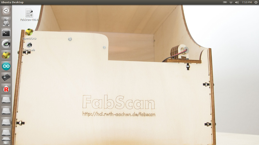
First Scan
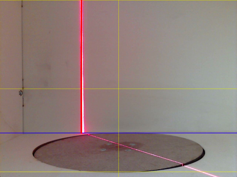
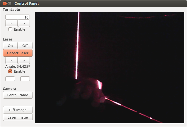
So after trying both the Canon and the Kinect as a "Web camera" we finally quitted and just got a normal Web camera and this solved the deal. Finally I was ready for the first scan, or so I thought. This time the software wasn't recognising the laser when we were calibrating the system as it should:
Once again I had to solve this problem and after several hours I found the solution, under "Detect Laser" in the Calibration menu you have "Angle" and here you can change the location of the red Bar that allines the laser in the Fabscan it was pre determined to be "-13º" which took it out of the screen: