
Here we are on week 3!! This week’s assignment consists of creating a parametric construction kit cut in the laser, where you may change its parameters so you may make it bigger or use a different material with different widths. And try out the Vinyl cutter so you see its capabilities. So this were my week steps to conclude this assignment
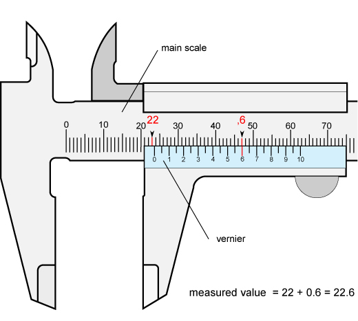
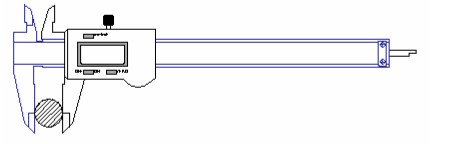
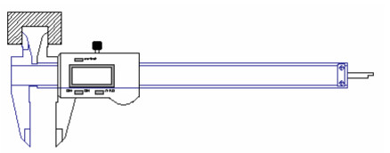
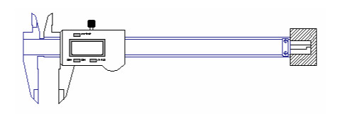
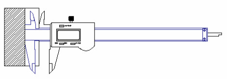
To take the reading you apply the Calliper and then you read the main scale and find which number does align with the Zero from the Vernier scale (lower scale) after that you must see which number perfectly aligns on the Vernier scale with the main scale and that will give you the decimal number. So with a Vernier calliper you can take 4 Basic measurements to your Project:
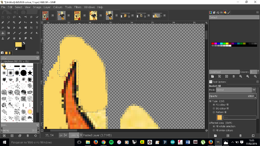
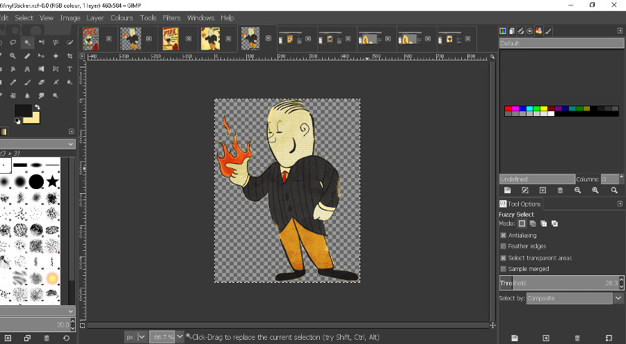
I wanted to further discover and investigate the tools and capabilities of both Gimp and Inkscape which are such new tools to me but full of potential, so I started with the Vinyl cutting and created a sticker:
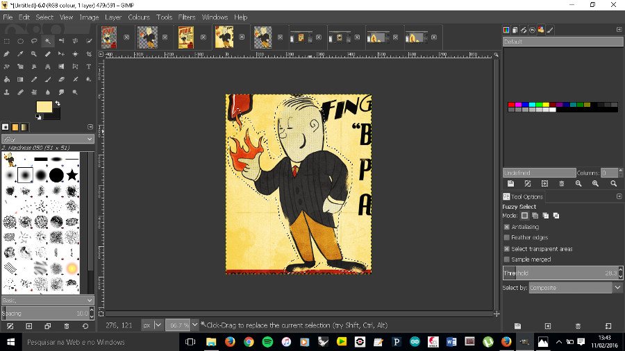
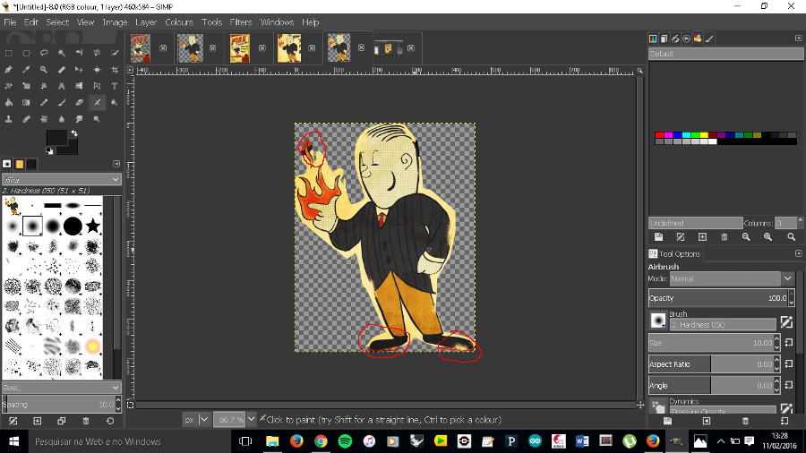
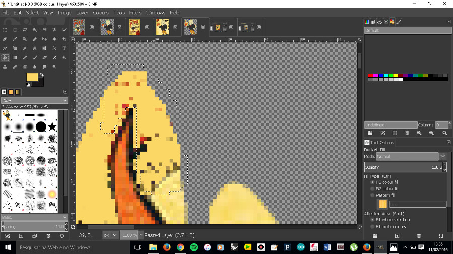
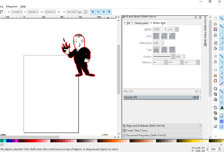
In Inkscape there is several things you can do to your image: I started by trying to make a Black contour around my sticker and started by using Trace Bitmap Using Trace Bitmap you have to play with the brightness levels till you get the desired result and you get a black and white version of your Sticker, that after selecting no fill and stoke to flat colour you get the contour. To centre it to your original image you must unable the snaps and snap both to one of the corners of Inkscape working area.
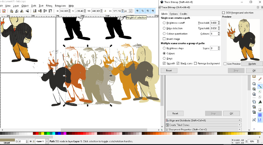
One other cool thing you can do with Trace Bitmap is using Colour Quantisation, changing the colour quantity and ungrouping twice the images you can create several logos in several colours based on the original logo colours.
After you are finished you have to print it on a plotter or printer with Inkjet Vinyl sticker without forgetting the alignment points (the process is different in the Vinyl programs, in the Roland Cut studio you must check file; Print and cut) this will make it possible to align in the Vinyl cutter on the next step.
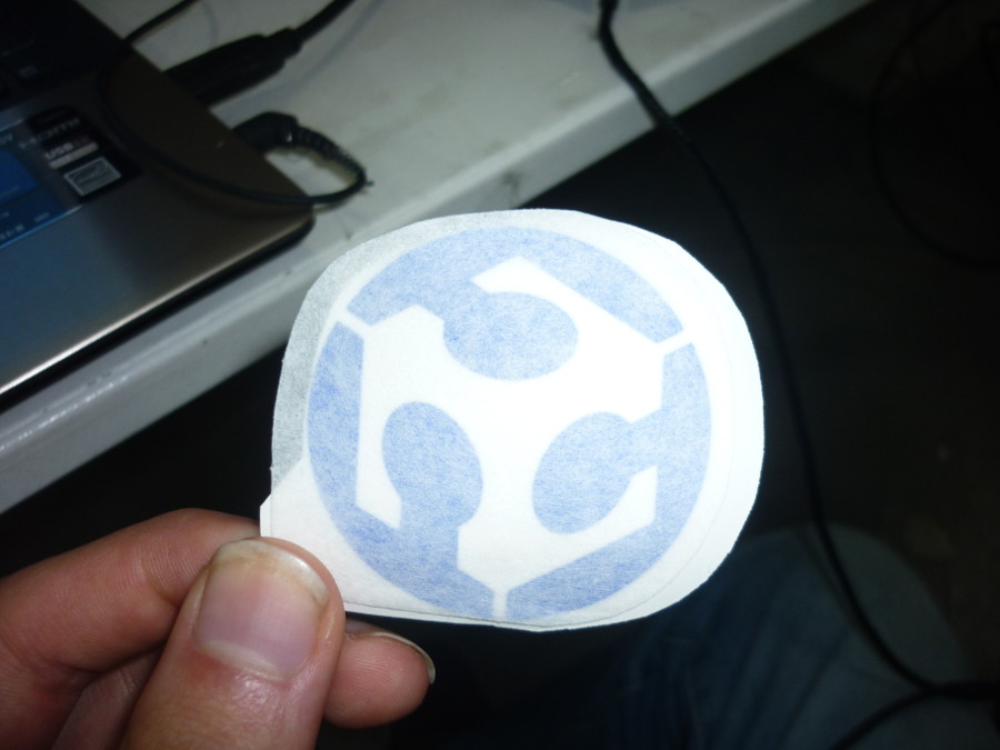
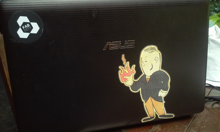
 After this I finally used the Roland program to add the alignment dots and to create the cut path to create my sticker using a special adhesive paper, this was the end result:
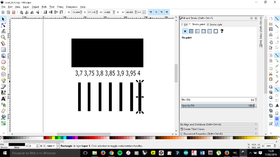
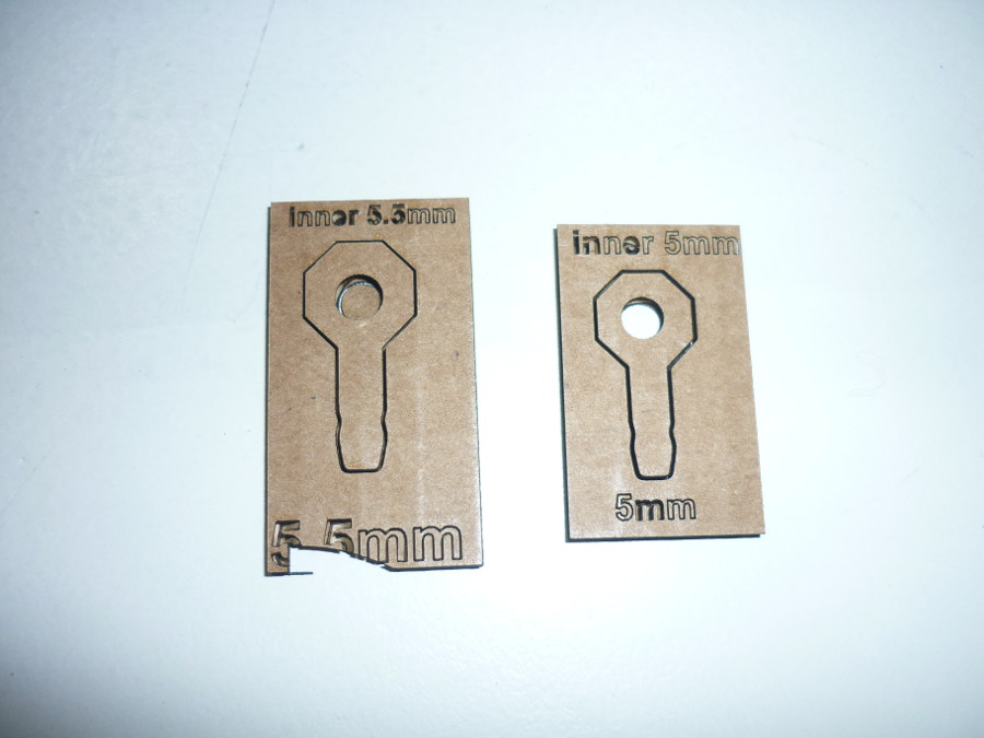
One of the areas I've been working the most this past years has been education. Mainly how technology can complement or even improve the educational process of kids. I wanted to do something that was as modular as Legos or K'nex, so BeeLinks are a new building block for kids to play around and create almost anything. In this assignment we had to make a parametric piece where we could change its parameters depending on the material you are using and its thickness. I remember as a kid playing with straws and coming up with crazy constructions but whenever I needed to create a link I would connect them using a litter so with Beelinks the Idea is to make it a much simpler process. Before any model can be made we must know which material will be used and its thickness so we can create a tight fit connection, after you have all this measures a kerf test must be made to visualize the best fit:
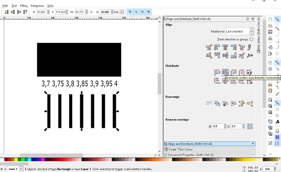
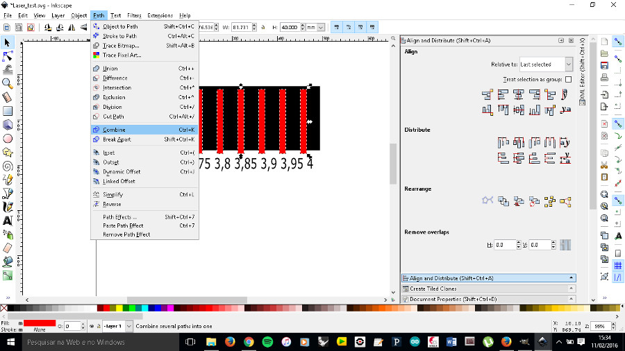
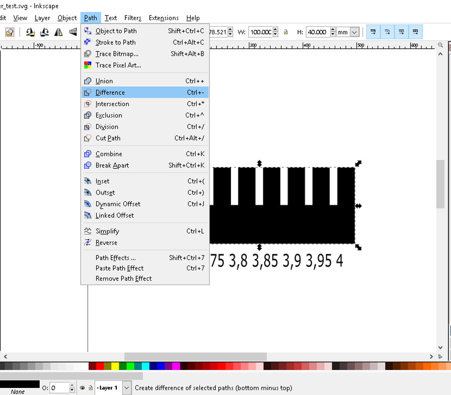
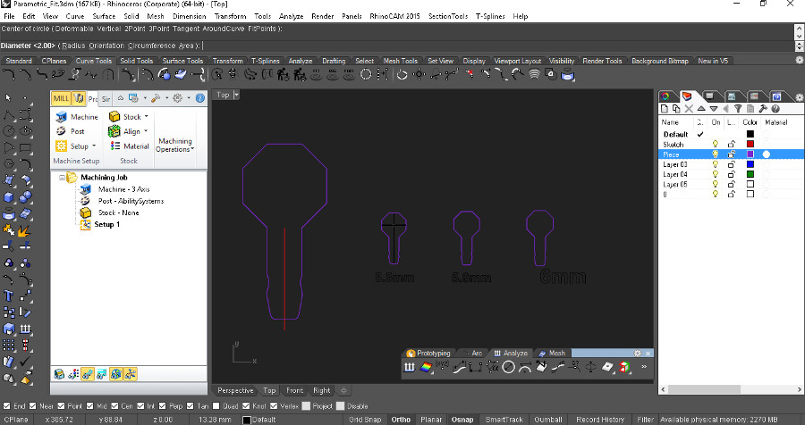
With this parametric costume made comb you can fine tune it to your material width and test the best fit for your project! After you have the measure for the best fit you must start to work on your project model, without forgetting that you have to make it parametric it will save you a lot of time if there is a size or material change. So I tried a new process of a type of parametric modelling in Rhino using blocks. Thanks to Saverrio Silli for this cool trick, you can watch his 5min tutorial here .
So after finding the best fit size of my joint I started modelling the straw connector in Rhino using Silli's method so if the first prototype didn’t work I could change the parameter in the block. Here are a couple of my first drawings:
For 2.8mm cardboard I used Velocity 15, Power 100, and Frequency 5000.
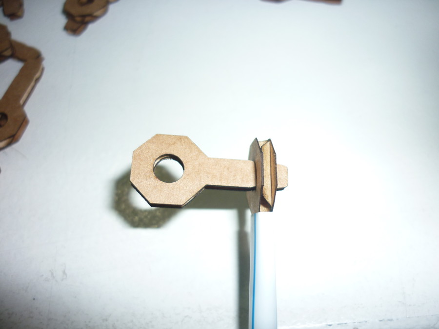
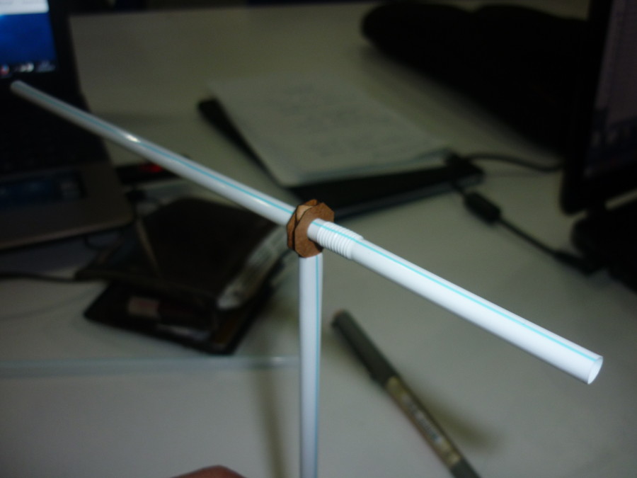
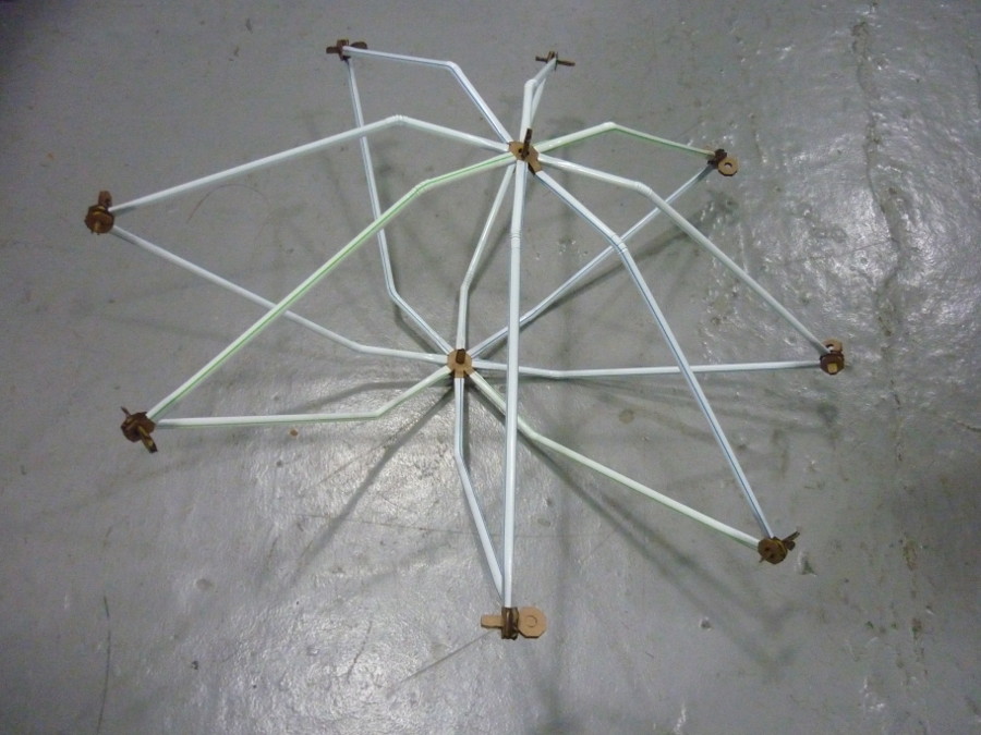
After seeing it was connected and fitted perfectly with both the straw and the Beelink itself the only thing missing is what could be built with this tool's! So I suggested my colleagues and friends we had a 10min break from the hard work, Laser cutting and 3D modelling so we could just have fun playing with this. And here are a couple of the results:
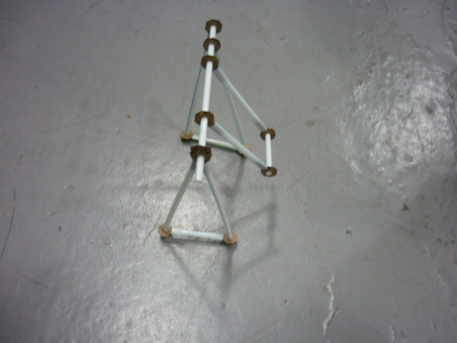
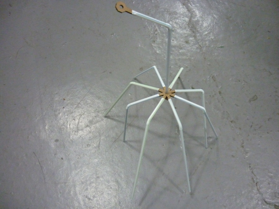
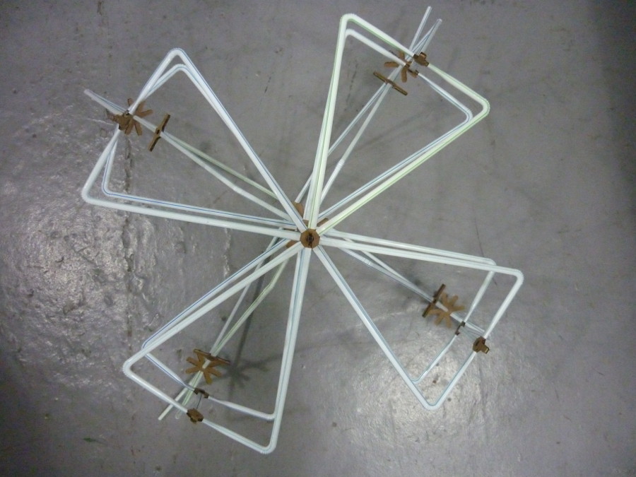
I had a blast with this project and would like to dedicate this small project to my nieces because I'm sure they will be the ones to have the most fun with it. In the future I'll try different materials and sizes! I would like to see if it is possible to use pvc pipes of different diameters. Integrating electronics and mechanical motion will also be very cool and will bring the project to a new Level. So share and play the download link is just below.