After speaking with Neal about my final project I concluded that it would be pointless to create a new extruder from scratch instead I
would work on top of a existing one, Improve it and give back to the Community.
Two months from the Final project presentation's a Team consisted of Cyrill, Inês and Pablo came to the lab with the goal of making the Precious Plastic machines I was introduced to
them since I was going to make a recycling machine and heard for the first time about the Precious plastic machines.
This was the project I needed, I have to make the extruder machine even more affordable and able to produce it on a local Fablab especially the electronics which are all out sourced!
Project Time line:
Before starting any project you should come up with a time-line and most importantly be aware that it will for sure not work accordingly to Scheduled! But it will put things into perspective!
So I decided to start with the Electronics and programming part of the project since, from experience,they are the ones that take longer and have more last minute problems.
1 week 24/05 - 29/05: 5 Days
- BOM of materials and order what's missing Mechanical and electronics
- Design the laser cut wood Hopper for extruder
- Laser Prototype
- Design Motor Controller
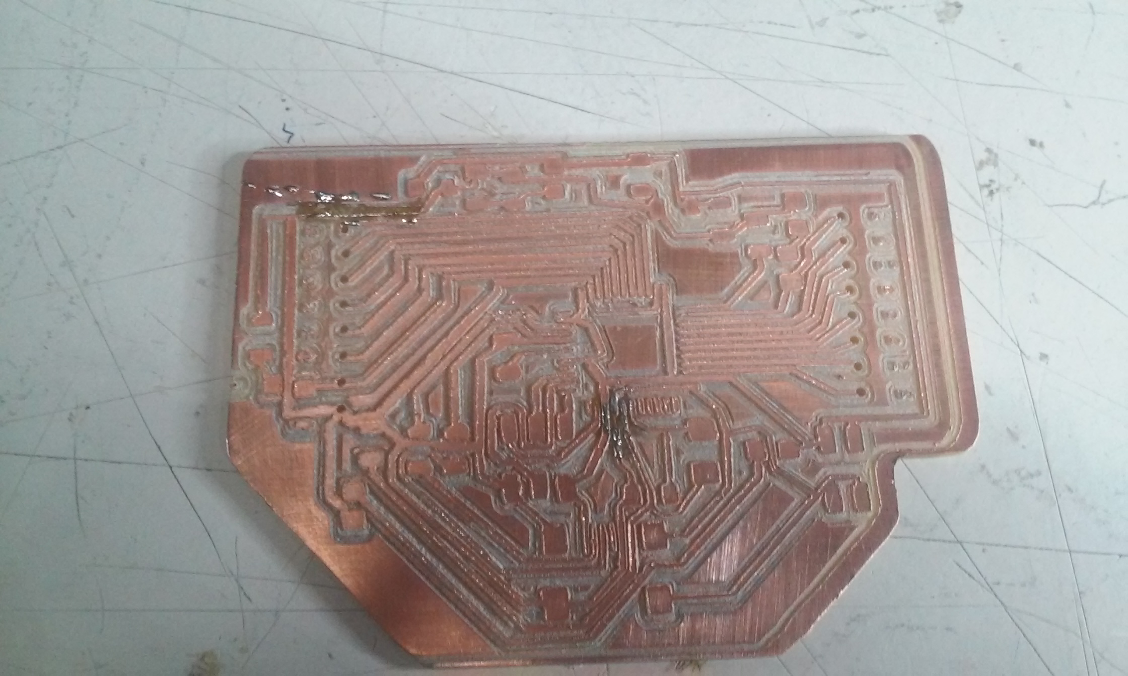
- Mill Boards (Leonino and Motor) (Done)
- Solder Boards
- Program boards
- Document
2 week 29/05 - 5/06 : 7 Days
- Look for how to make THREDS and where to get Wood Drill Bit,bearing.
- Make a Solidworks virtual model of the machine with material that you have already so you are sure there are no problems
- Get Drill bit (26x600mm would be ideal)
- Start building Machine
- Join all the electronics and programming
- Processing / Arduino Interface
- Solve Problems
- Document
3 Week 5/06 - 17/06 : 12 Days
- Finishing touches
- Prepare presentation document
- Help in other Final Projects
- Present on the 17th
Total 24 days
Mechanical & Design
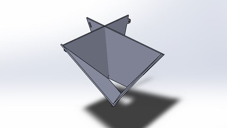
Hopper:
Software: Rhino and Solidworks
Sketch the side of the hopper as a rectangle with the desire width and length. After that made the "Triangle" that with the connectors after that made a boolean difference so it would be aligned :
Extrude as a bose(Angle)
Shell it
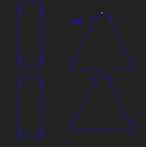
Use Convert to Sheet Metal To divide the pieces individually, use the base surface s the initial cut:
Use Unfold Command:
Flatten Command
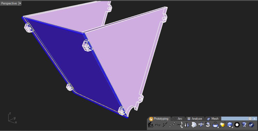
Problems:
The Connections weren't working, in Solidworks it was giving a funny shape when modeling the assembly of the hopper.
Changed to Rhino and redesigned it using a different approach to the problem.
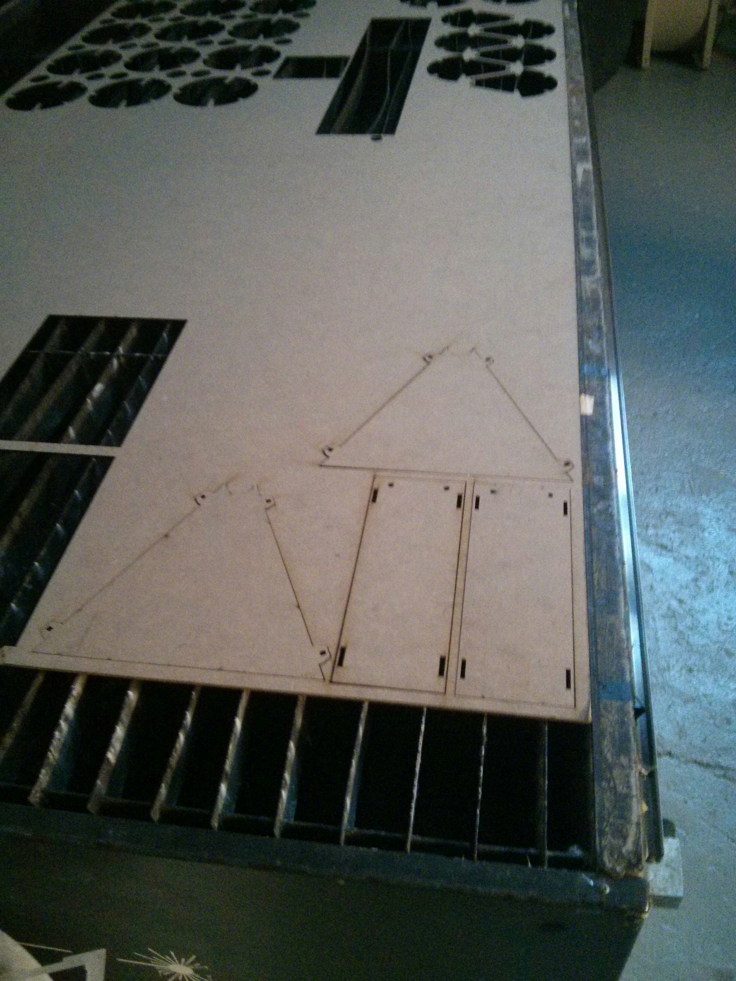
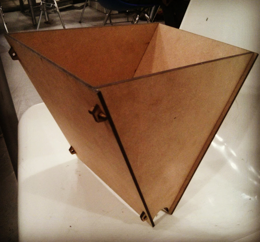
Laser Cutted part:
Parameters used:
Power: 220
Speed:15
Made a small joint test which was a great idea since it helped me solve several problems before cutting the final parts! The cut and pieces worked better than expected, its such a tight fit that it didn't even need the pressure pieces.
Unfortunately I started doing a 3D model of the entire machine since there were several mechanical differences from the precious plastics designed dew to differences in material and I encountered that the hopper for the new dimensions was way to big.
In the end it worked super well it was really tight fitt!
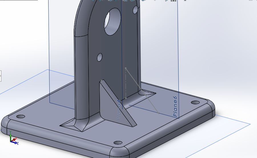
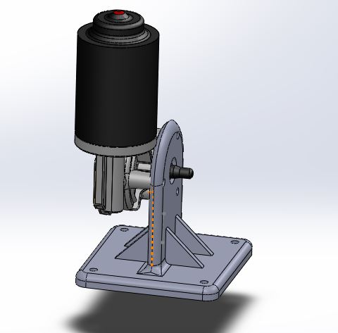
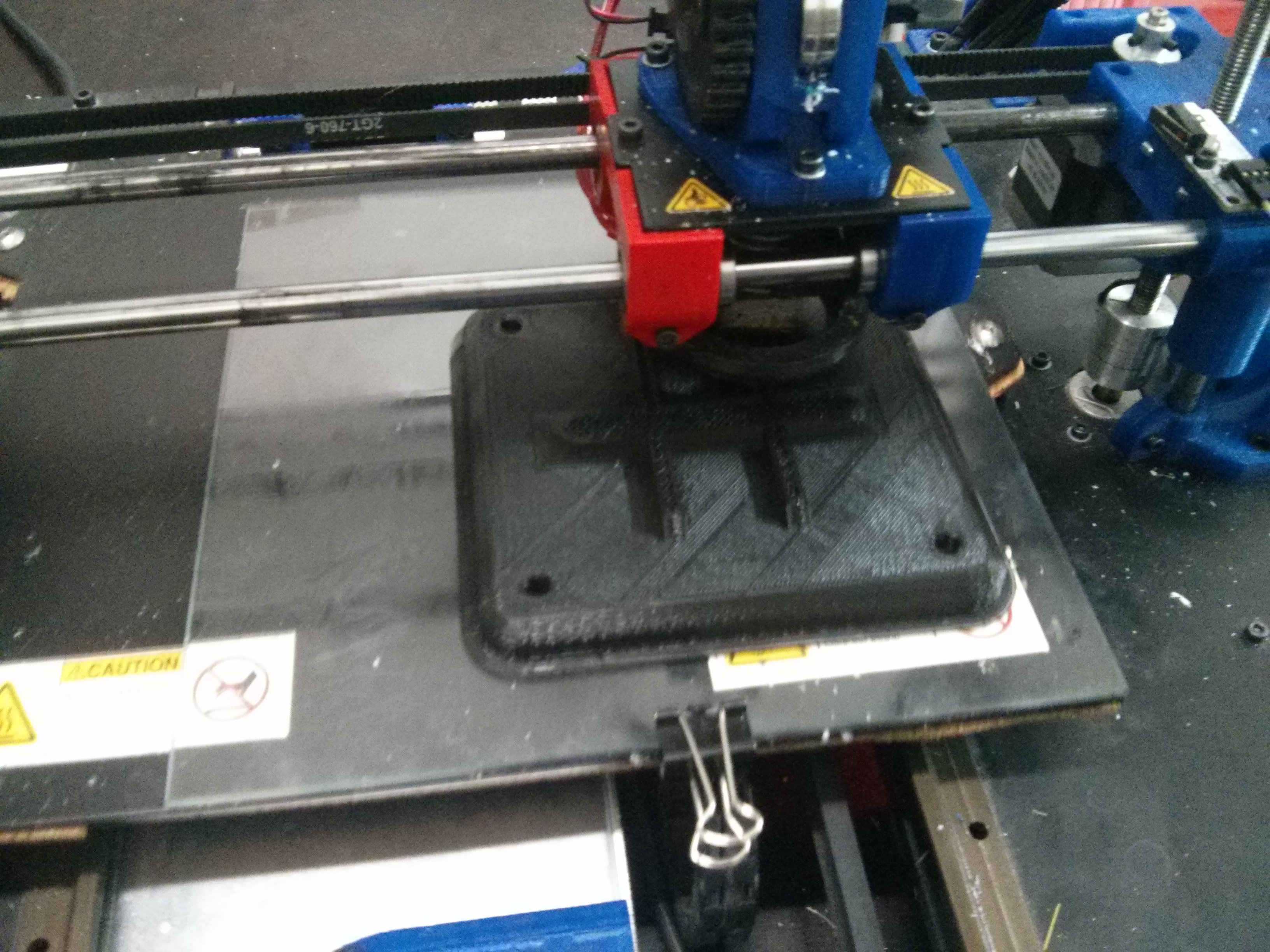
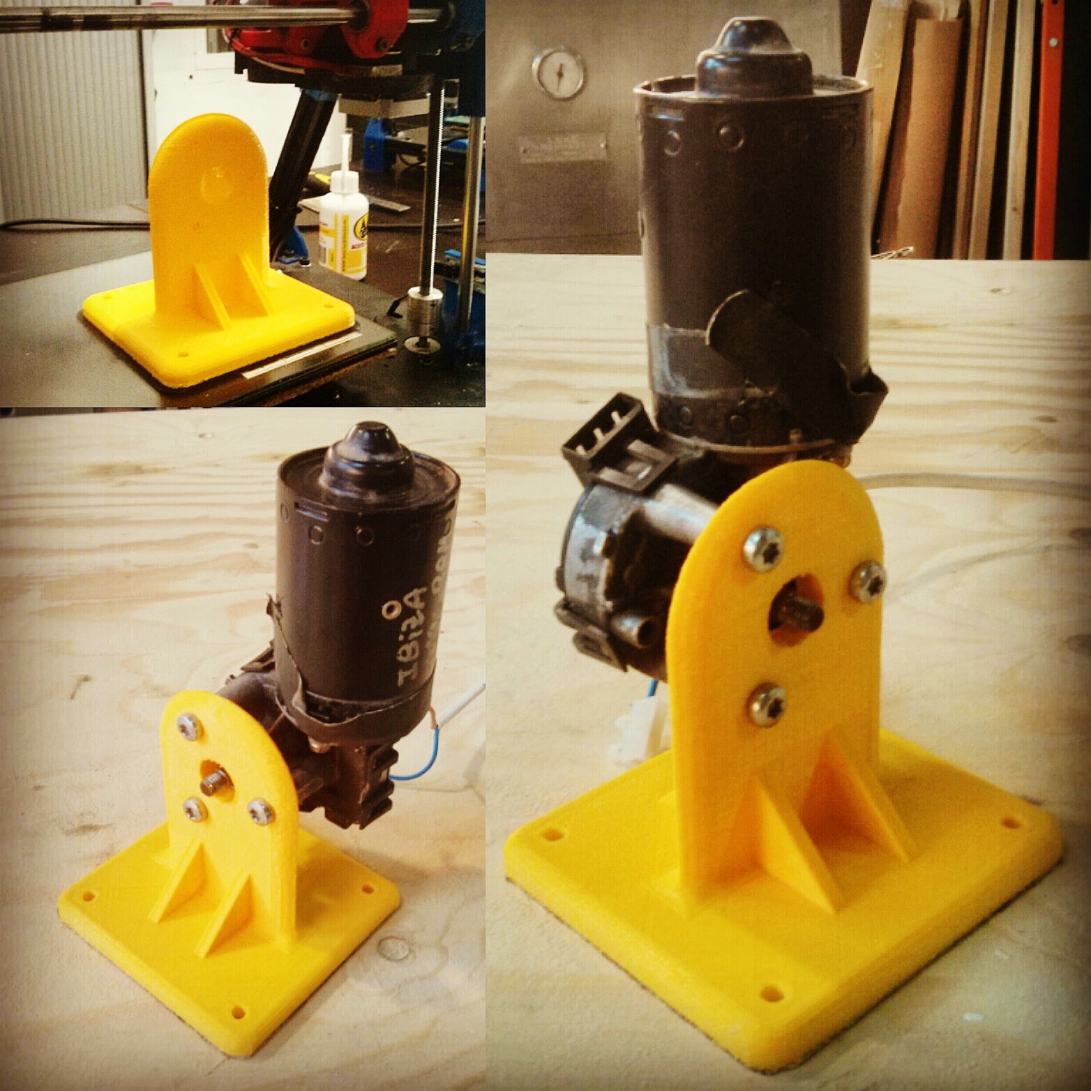
Motor Holder:
We first used a windscreen whipper that Ferdi had.
Designed motor holder in Solidworks and 3D printed.
After finishing I found out two holes weren't completely aligned so after looking more in depth I found a 3D model of the Windscreen wiper on Grabcad.
Lesson learned always triple check the holes and even If you aren't sure look for ready made models were you can base the alignments on.
This is why it is so important to fail as Astro Teller from Google X said we learn so much with failure!
In the end I managed to correct the mistakes and this was the final result.
Metal Frame:
To make the metal frames I used the dimensions and design released by Precious Plastic located in the download link. Using this cool new Hydraulic cutter in Fablab Barcelona I was able to cut all the parts. You can adjust the speed as it goes and the angle of Cut.
After that a couple of pieces needed holes so I used the Metal drills and the drill press to make them.
In the end all that was missing was to solder, I learned the basics with Martin but in the end we didn't have a soldering station on time to make it till the dead line so we went to a solder house right around the corner.
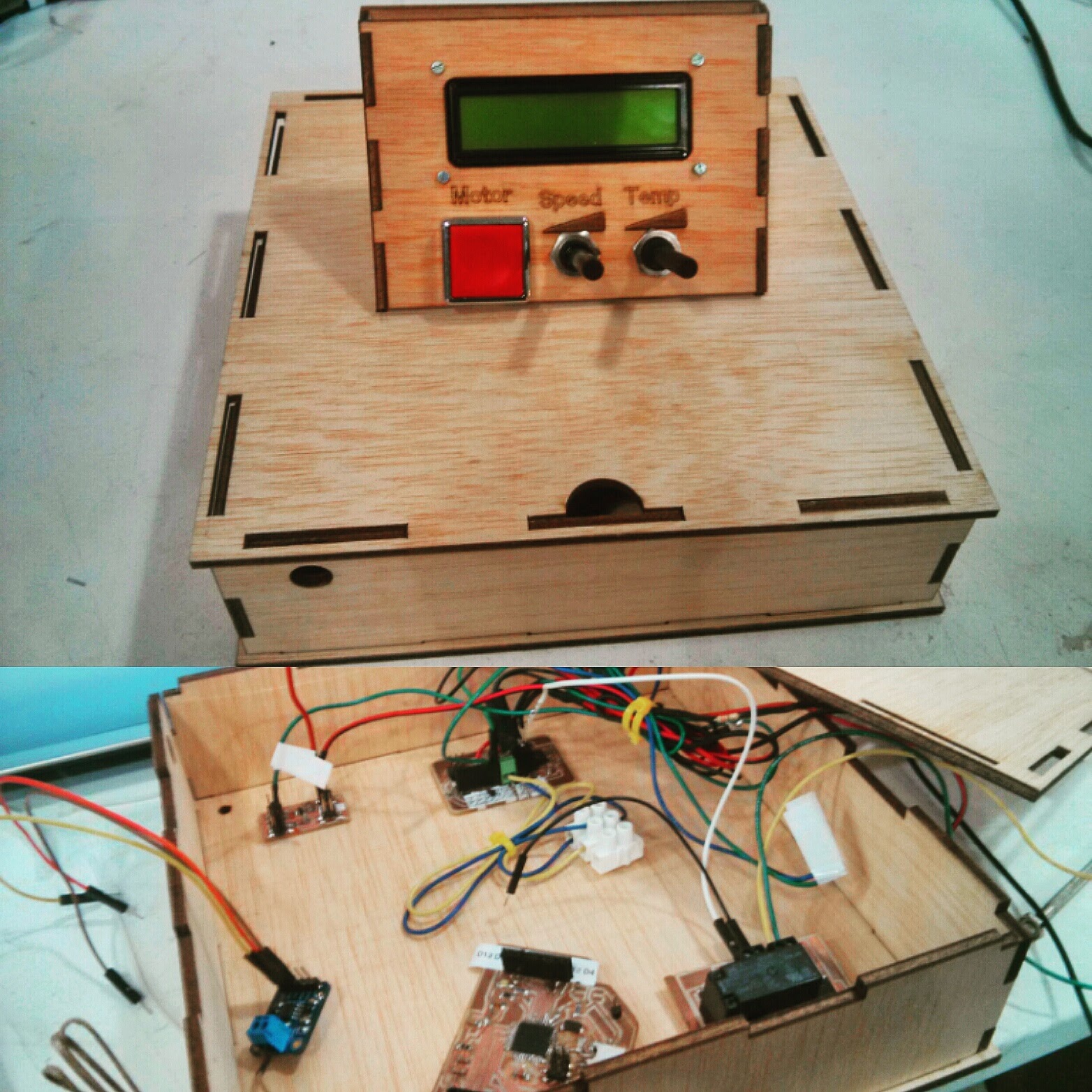
Electronics:
Before jumping head straight to the electronics I wanted to organize my self and understand how could I divide the system in different parts to make it modular and use the Spiral Prototyping system! I came up with this MindMap together with Guilherme:
Eagle:
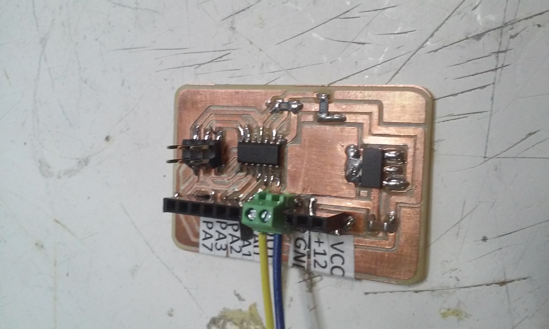
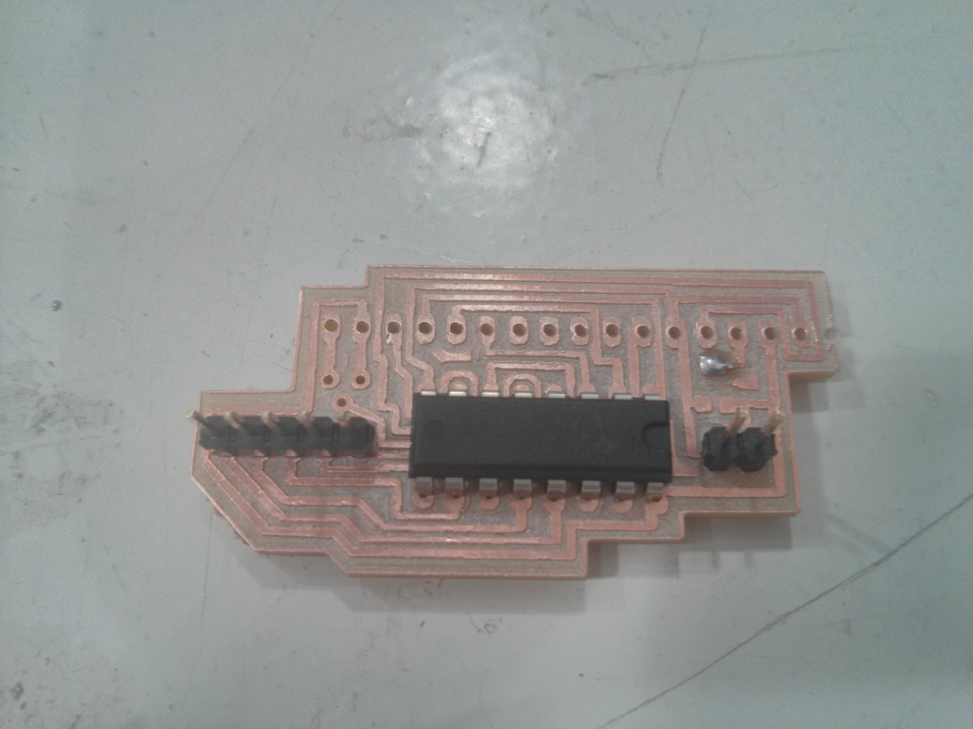
Motor Controller:
Started Designing the board in Eagle first version
Motor Control With Potentiometer in Pin PA0:
Connect the ISP and the FTDI Cable to program using the Arduino IDE
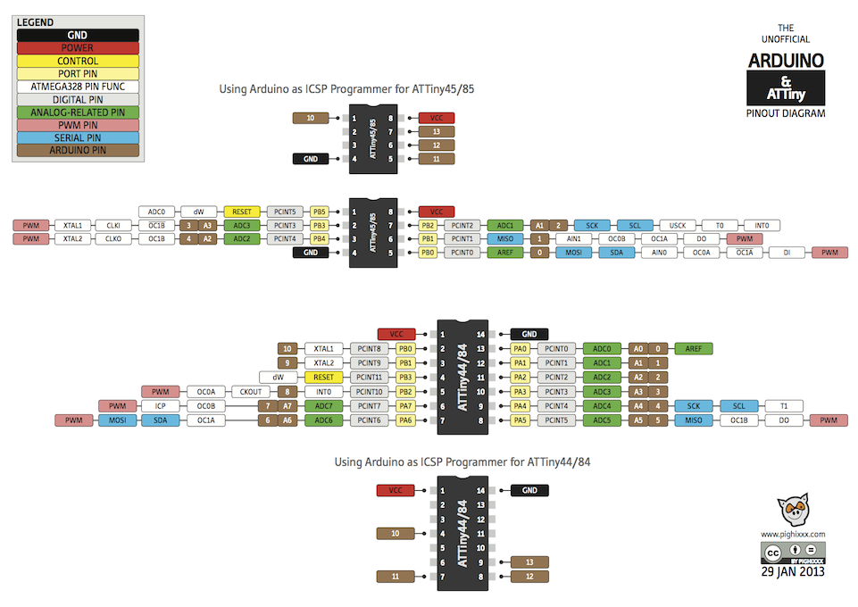
Port numbers Attinny44 to Arduino
Very good reference for PIns translation to Arduino IDE
Problems:
- Do not use Pin PB0 it is not PWM change for any other of the Pink in this table
- Current was to low the motor wasn't turning increased to 3A
Temperature Controller:
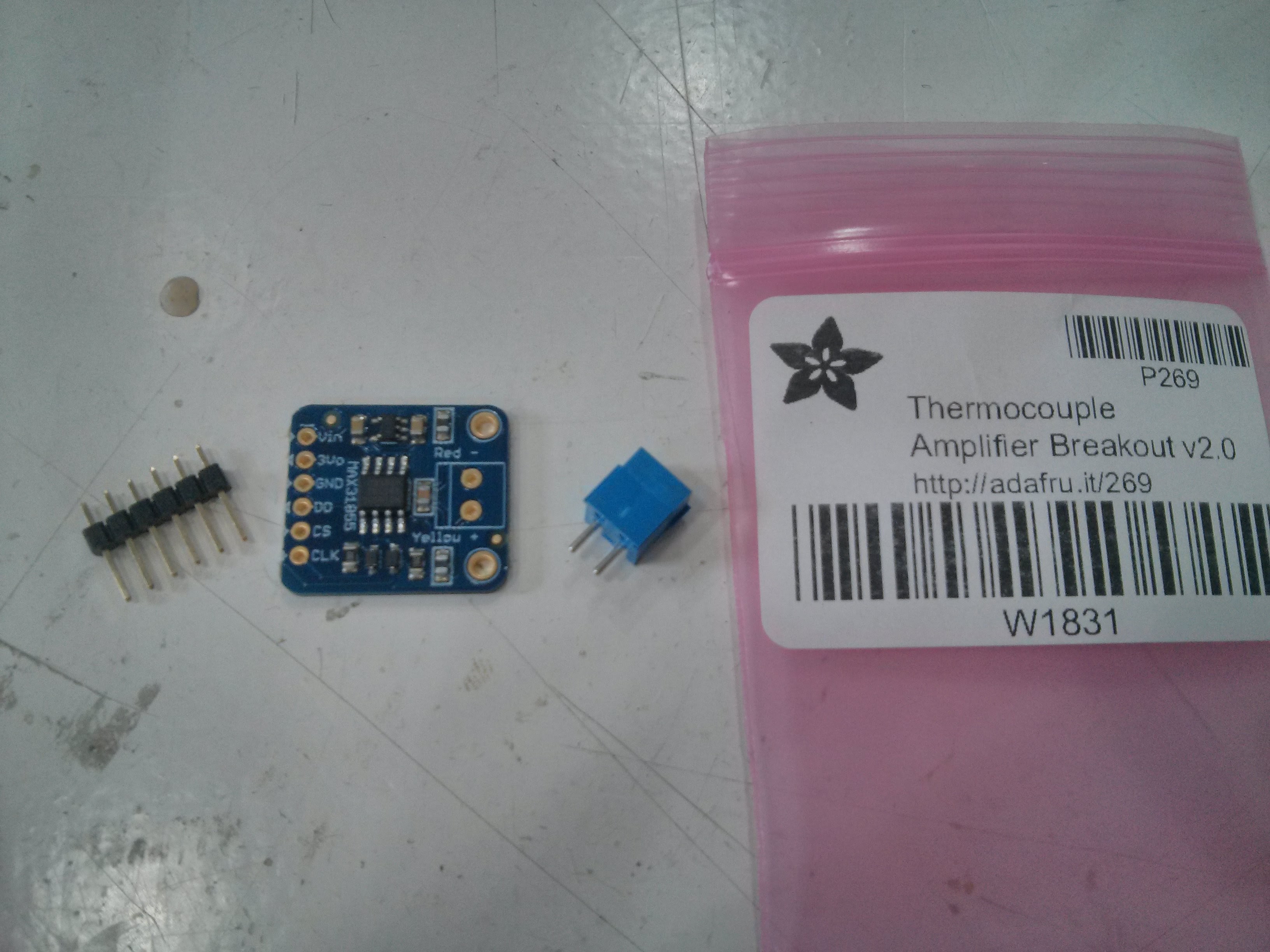
The temperature board I bought it from Adafruit as Ferdi advised It would be way to complicated to make it work.
Relay For Activating the Heat bands:
The idea is through a signal of the Leonino it will activate the MOSFET that in turn will activate the Relay that will Feed the heating system with the needed 12V.
Temperature Sensor activate Relay Using a Thermocouple and Adafruits MAX31855 Test:
For our examples DO connects to digital pin 3, CS connects to digital pin 4, and CLK connects to pin 5
Arduino Library:
If you have the newer MAX31855 breakout, download the MAX31855 Arduino library code by going to the Github page and clicking Download Source.
Then uncompress the folder and rename it Adafruit_MAX31855 and install it into the library folder according to our handy tutorial.
Here is the result of my test the program is located in the download link.
Problems:
- Relay was to big for the one I used in Eagle
-Arduino pin sending signal was not connected to the ground, electrons flood to no where
- Forgot to use Mosfet so I bought a transistor first
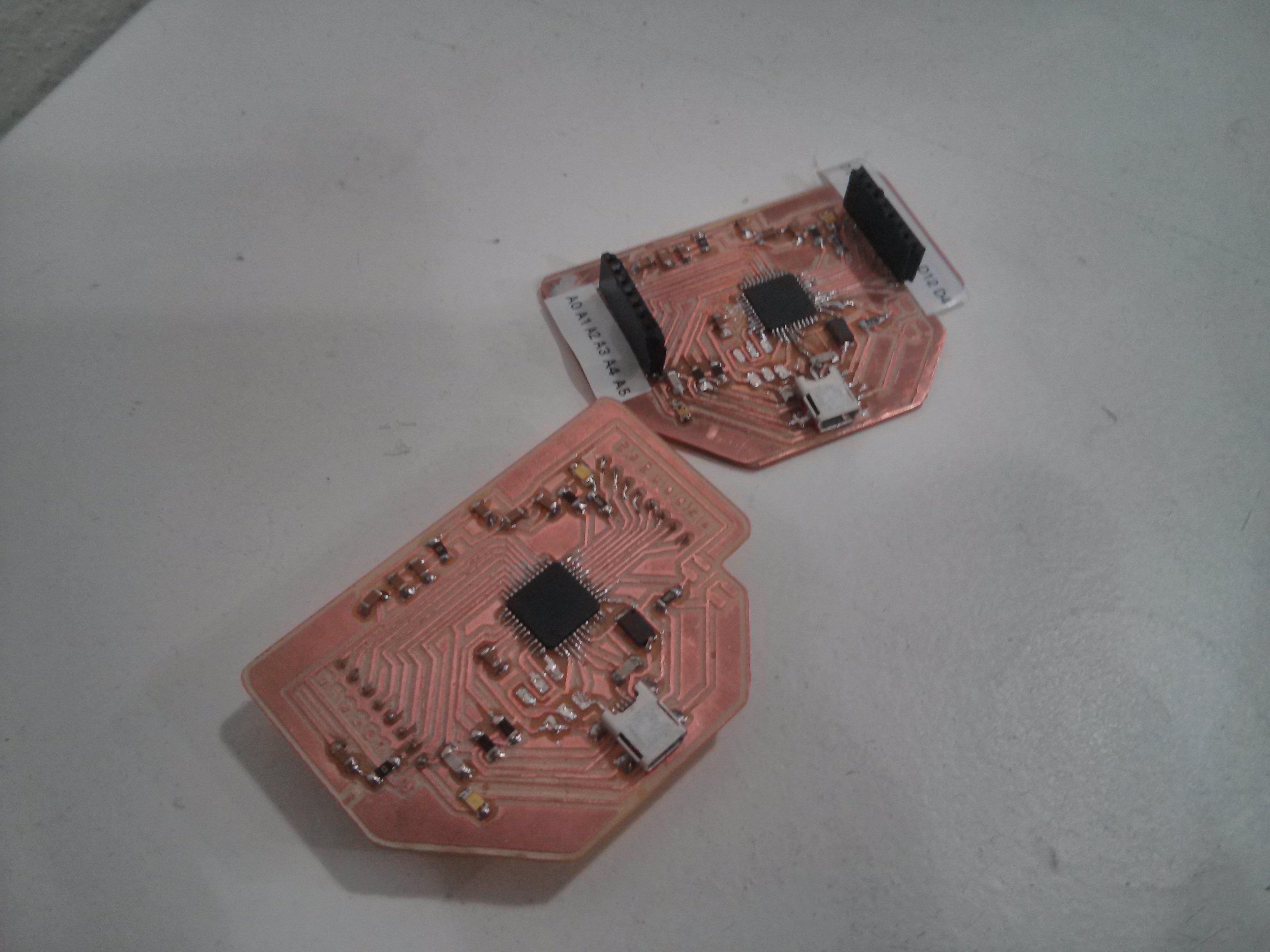
FabDuino:
Designed it already in a weeks assignment but hadn't the possibility of producing it.
Problems:
After milling and soldering, when doing the connection testes I found out that the lower part of the USB case are conductive which meant 4 of the board traces were connected, so I solved it by sticking isolating tape beneath it and the soldered it again.
But still two traces were connected and after De-soldering again the Usb I found that two of the traces had a small copper leftover making the connection.
It was giving me a connection error Usb port not recognized, even after changing the crystal that I put wrong for the 16HZ one, made a new border and after trying several times and changing to mac it finally installed the Bootloader.
You just have to plug the mini usb and upload the bootloader.
LCD:
Pin Reducer for the LCD:
Datasheet Shift Register
Use a Shift register to decrease the number of pins used in the Leonino by using serial communication with the HC595 chip Datasheet Shift Register
This ended up not working in the future I would like to test this again.
Instead I bought a I2C board that connects to the LCD
Datasheet Shift Register
LCM1602 v1 was the board I used to connect I2C , this is the Tutorial for make the connections and program
Tutorial
Datasheet of LCM-S01602DTR-M LCD to compare to pins connection of Arduino Hello World LCD example Schematic Datasheet LCD
Process:
Find your serial clock pin (SCL) and the serial data pin (SDA) in your boards, My Leonino SCL is D3 and SDA is D2.
I had to create new paths my board didn't have does pins connected must update my board to have I2c Pins.
In the Motor Controller is SDA (MOSI pin) SCL (SCK pin).
Final:
Its amazing the potential of the Spiral Prototyping its so easy to debug each system. Now its time to join everything together and hope for the best, Lets start with the electronics and make a Case for it.
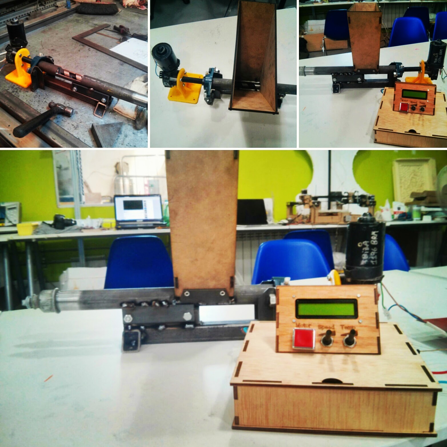
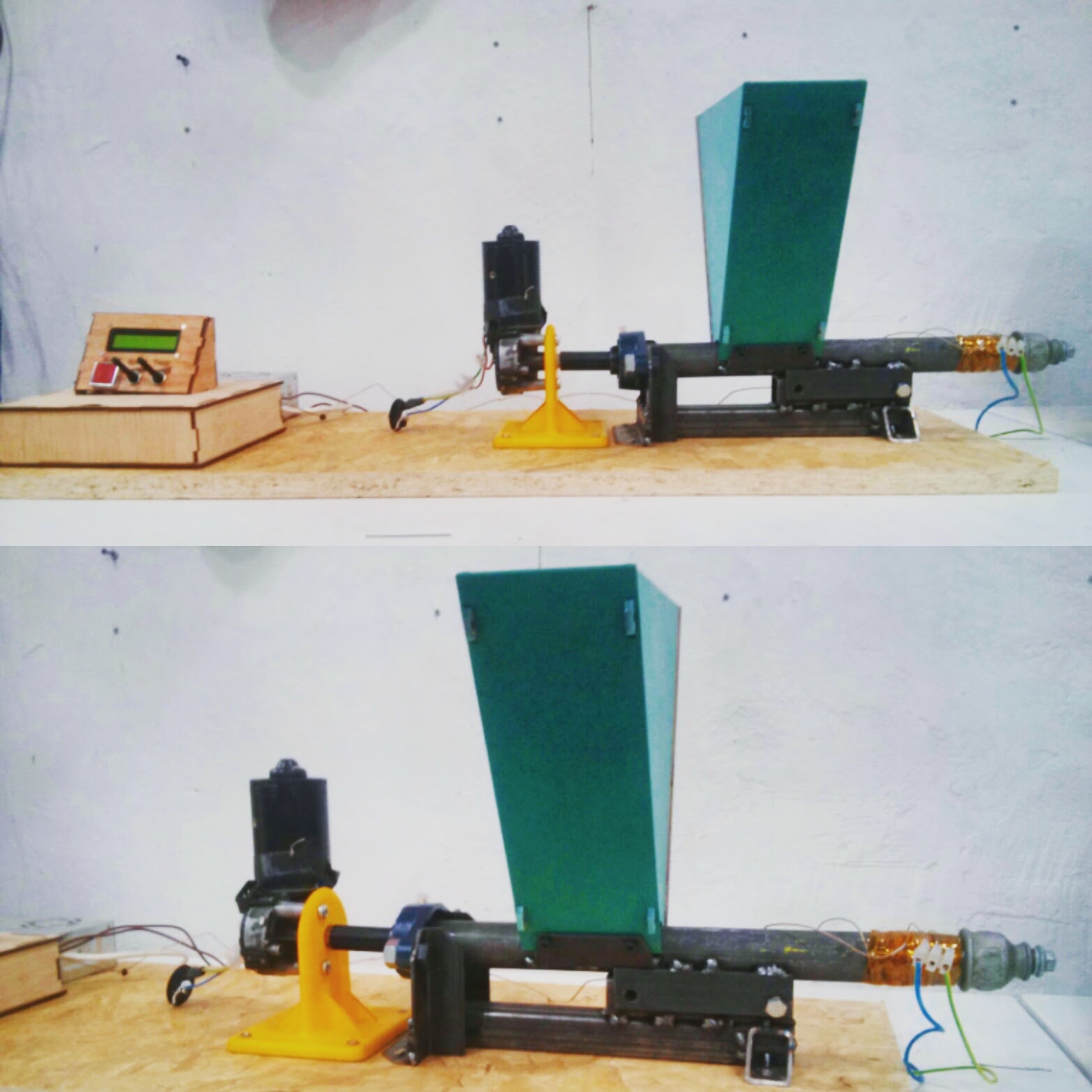
Afterwards connect all the Mechanics and the Motor:
Final Result:
The system worked perfectly together and it looks awesome! Unfortunately I didn't manage to extrude a plastic because the machine was used in the IKEA workshop in which PET was feed to the machine but the user used the wrong temperature 160ºC instead of 250C.
The machine will be unclogged and they will send me a video of my machine extruding nicely plastic.
This was a Amazing process, a lot was learned and a lot more is gonna come in the future. The choice of doing Fabacademy was life changing and one of the most important I made.
See ya all in another Time Fabers!
Final Presentation Video