Machine and Mechanical Design
Assignment:
Make a machine, including the end effector.Build the passive parts and operate it manually.Document the group project and your individual contribution.The assignment for this week is to Design and build a Machine.
It's a group project so it's going to be an exciting week.
Between our group we made a brainstorm of possible machines we could build and the degree of axis freedom we would like to work with.
We ended deciding we would build a circuit drawing bot for kids and grownups. This was a great starting point and so we decided to divide our project into smaller and more manageable tasks:
Xavi Dominguez - Programming
Arnau Tàsies - Design / 3D Modelling
João Leão - Electronics / 3D Modelling
Katerina Labrou - 3D Modeling / Programming
Joe Galea - 3D Modeling / Machine Extruder
Although we decided to divide the tasks we wanted to switch between each other so we could have an idea of the different work flows.
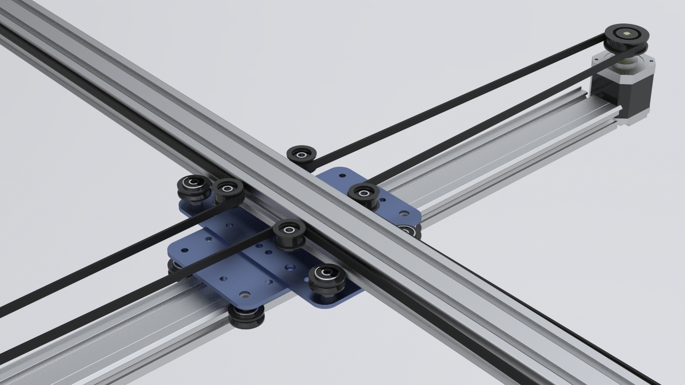
We are going to start by working in the given MTM Kits from Nadya and create a prototype of our desired goal so we can understand how the Nodes, Mechanics and Programming works. As soon as the prototype is well on it's way we are going start designing the Drawbot 2.0 and its mechanics, based on a coreXY system.Design process: Solidworks & Rhino
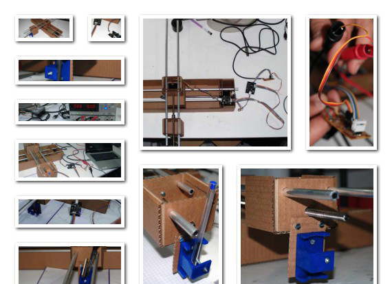
The prototype
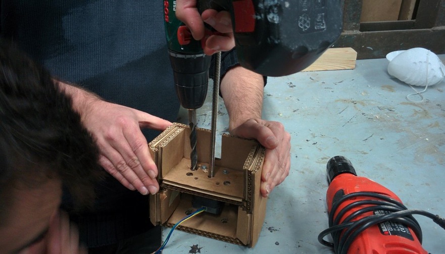
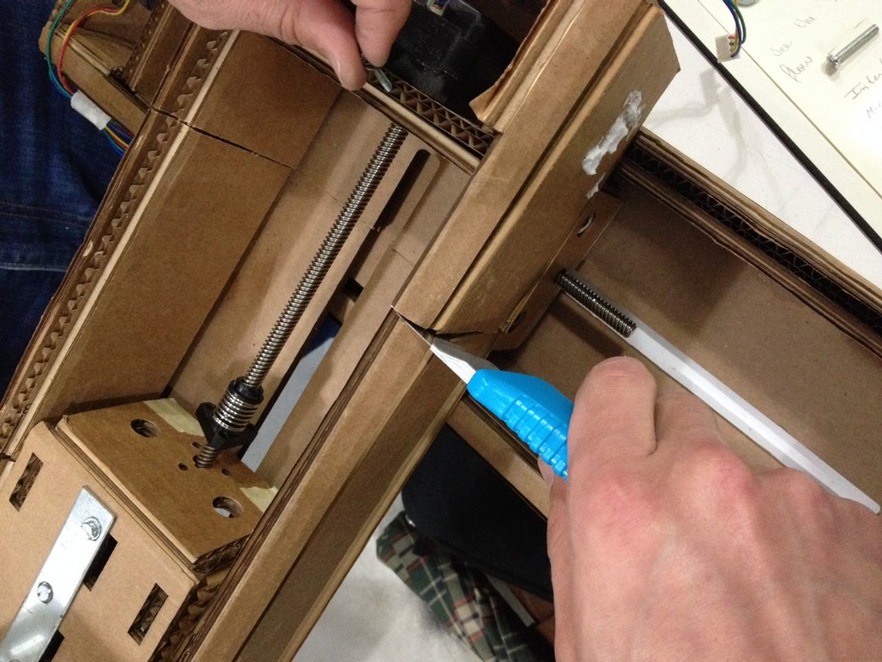
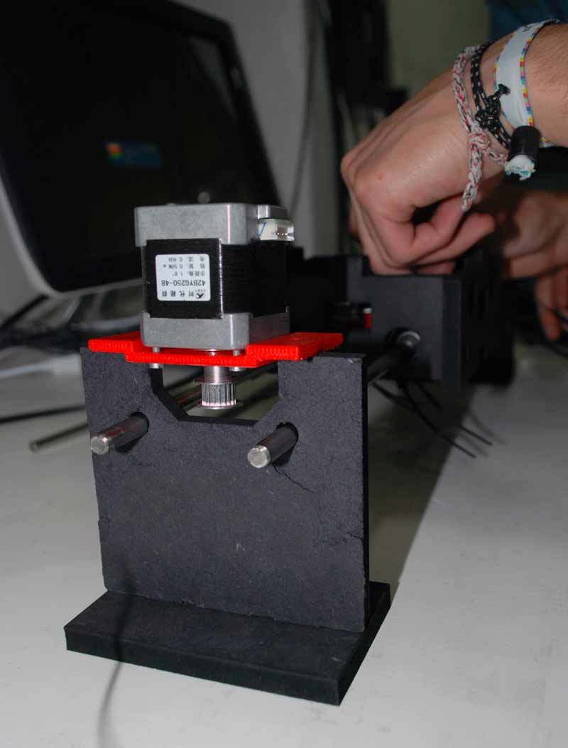
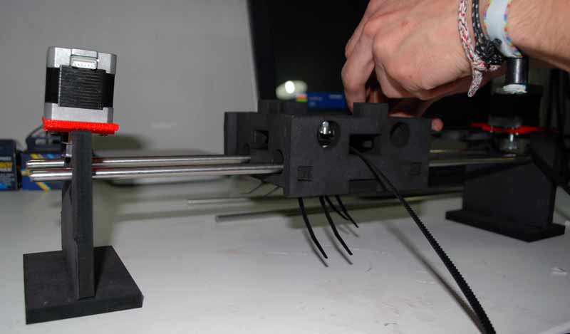
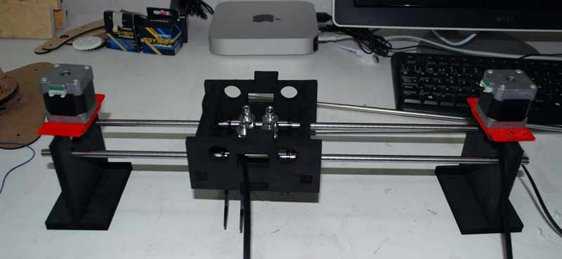
We had a some of the cardboard modules from last year and so we started by using them as a means to create a fast prototype of what we wanted our machine to do.
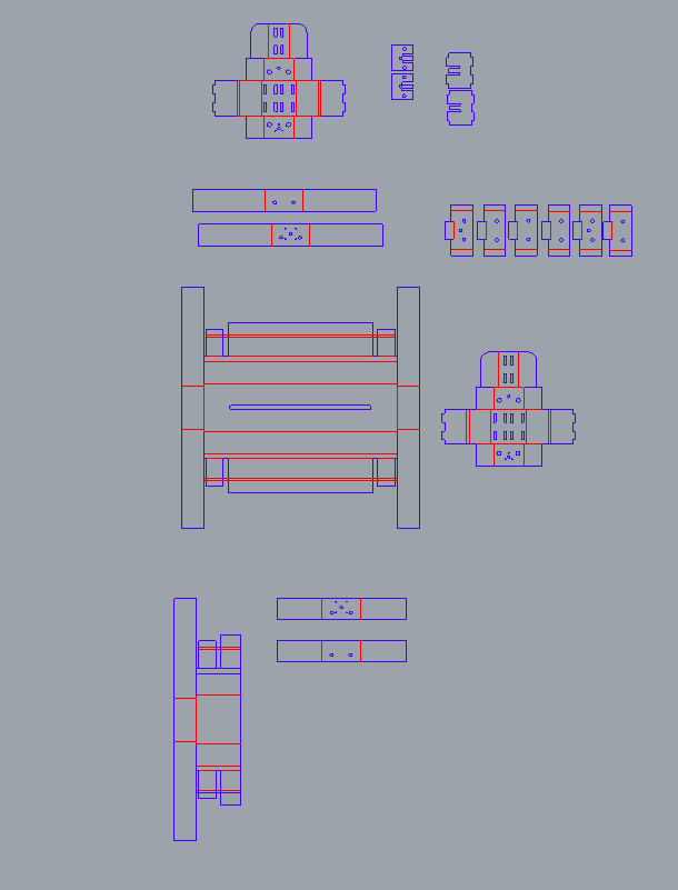
Then, we made the design changes to the original Rhino files with the changes we made to the fast prototype and laser cut it.
As a starting point, we used the Rhino design files from Francesca Perona, you can download them here.
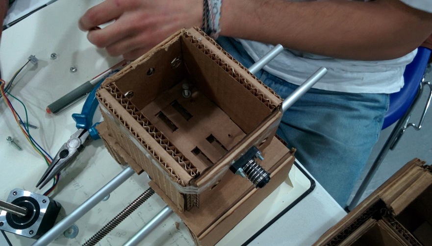
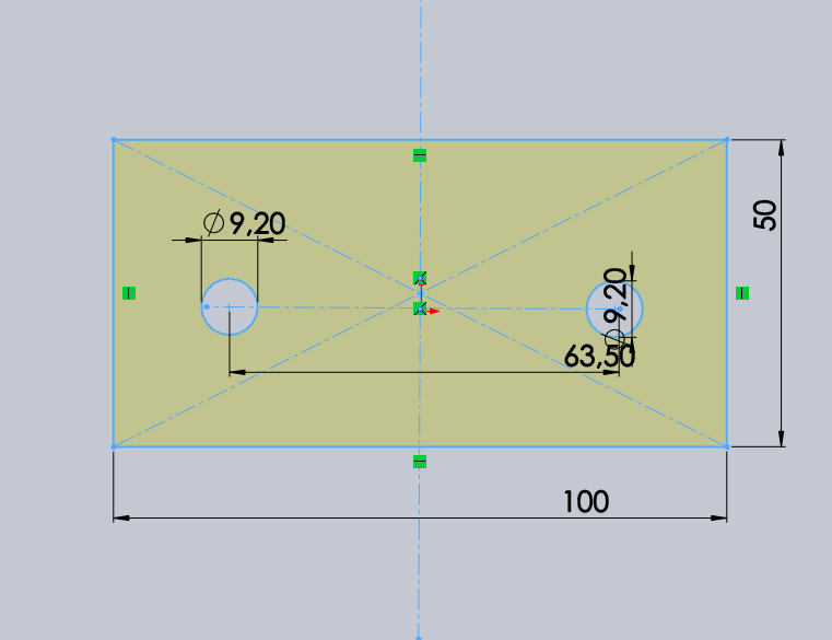
We intended to make the housing of the x,y axis lighter, adapt it to the 2mm cardboard we would use, and correct some details - such as the heights and sizes of the holes for the shafts and the screws.
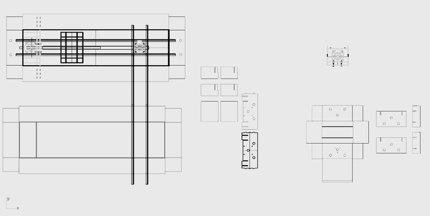
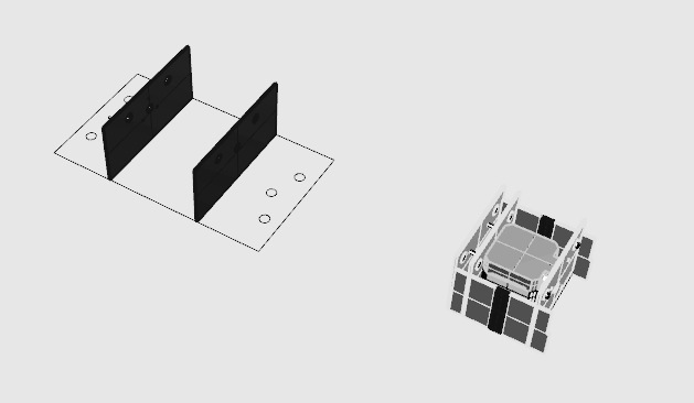
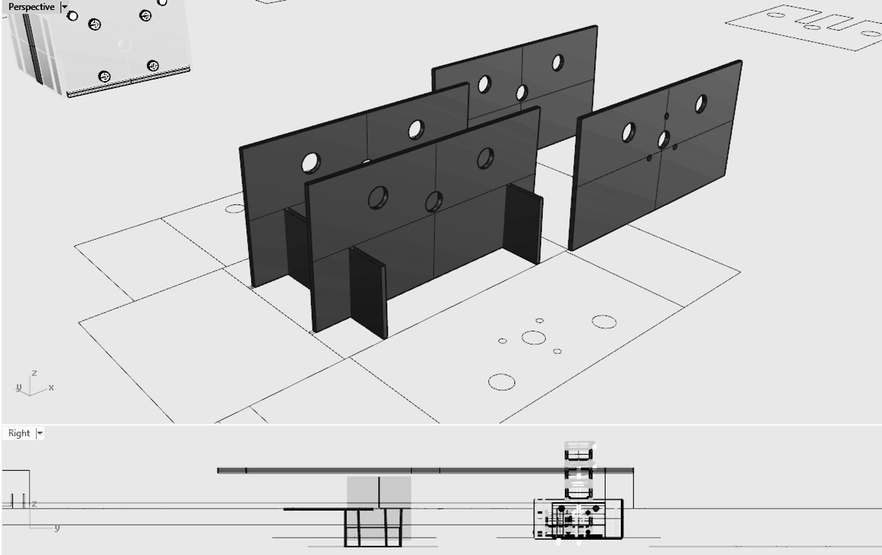
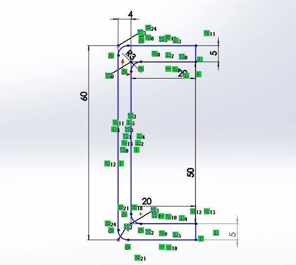
Starting with building the 3D model of the axis, in order to visualize our parameters, we gradually build the outsides, and then moved on to the inside parts which will hold the motors and support the whole structure.Having the 3D design of our machine made it is easier to understand and troubleshoot the file for the laser-cut. At the same time, it is helpful in terms of optimizing the machine structure and parts for the following week.
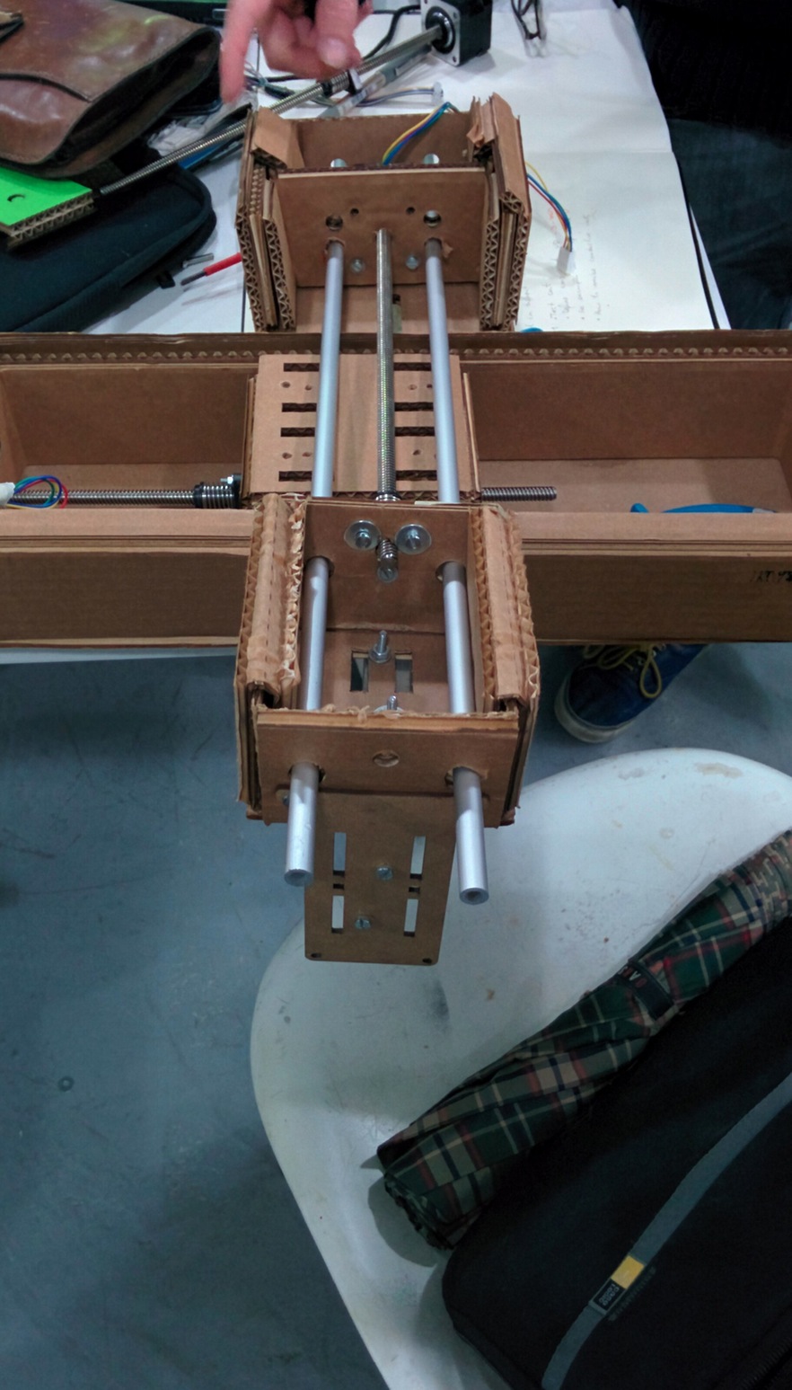
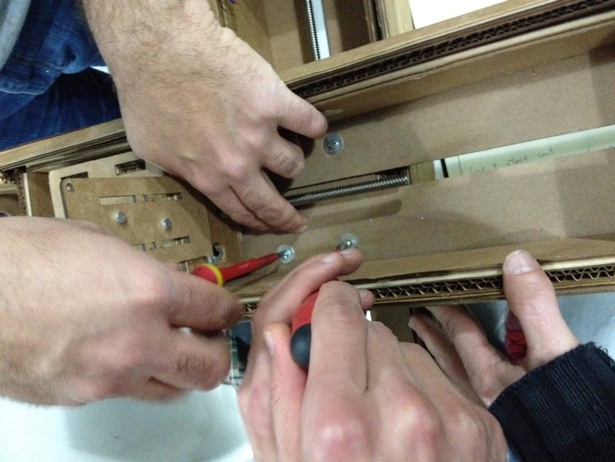
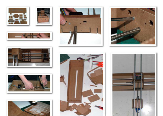
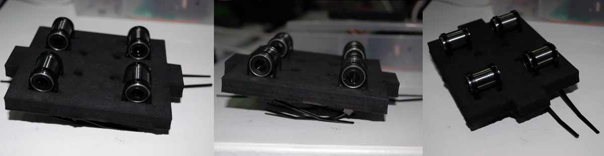
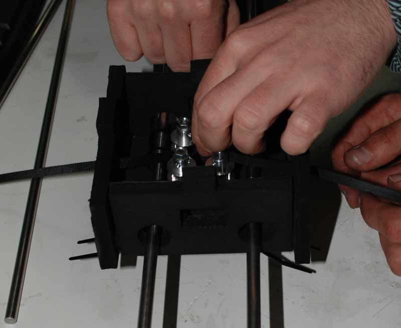
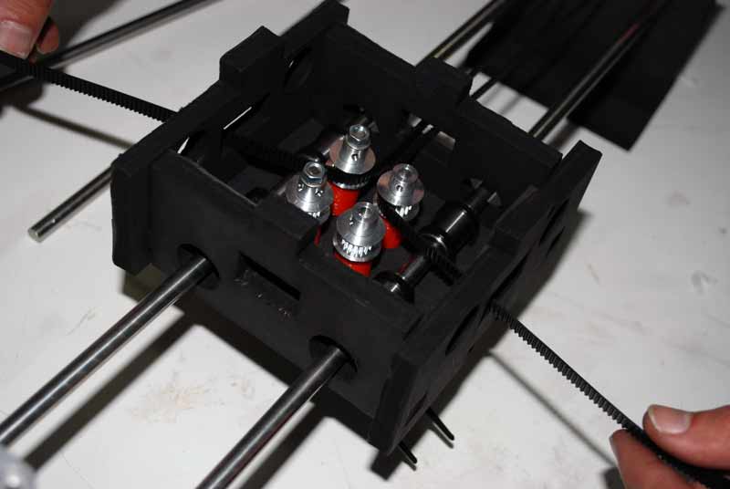
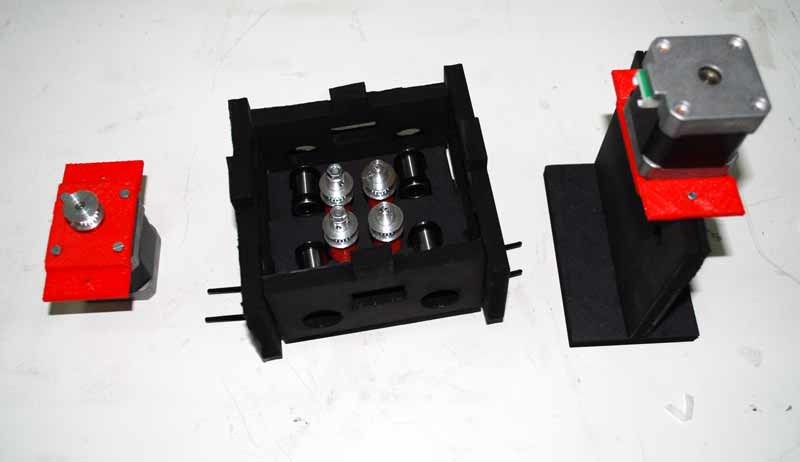
We used 2mm cardboard, and get rid of a lot of cardboard. The structure is much lighter, but stiff enough. The next images explain the assembling process for the prototype machine.The coreXY drawbot
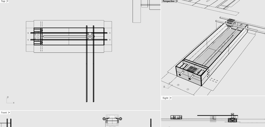
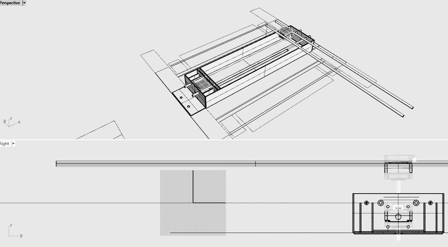
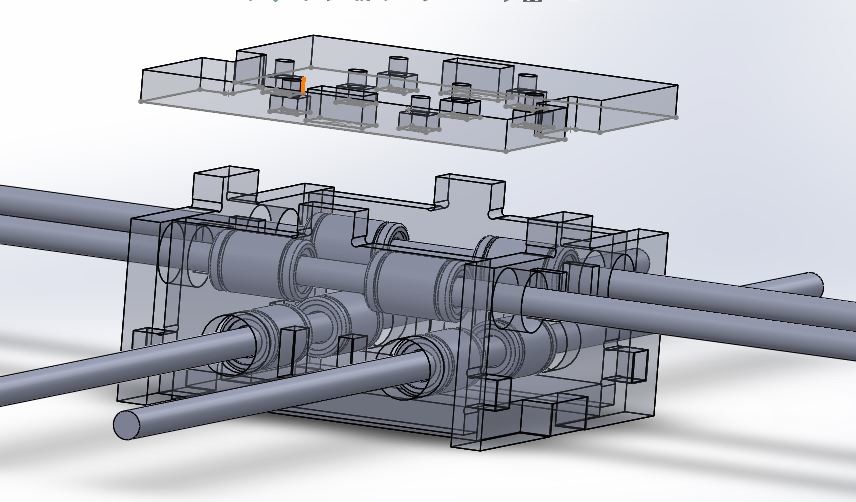
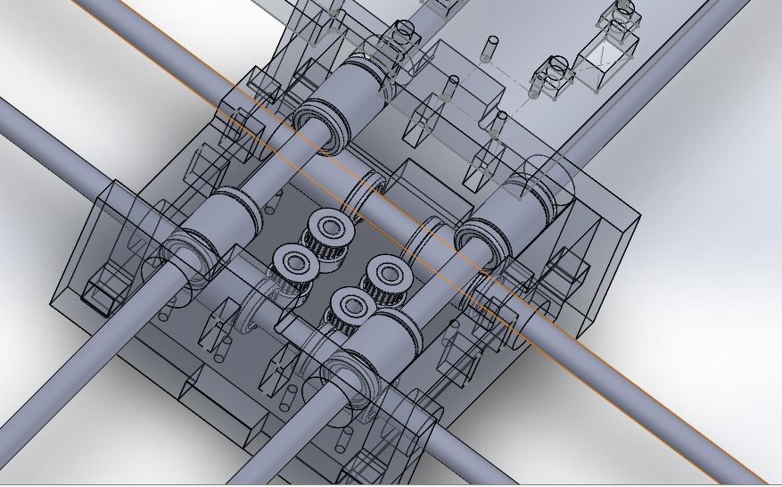
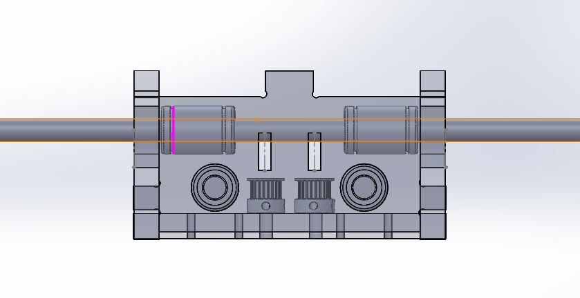
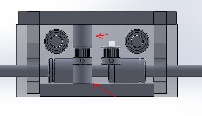
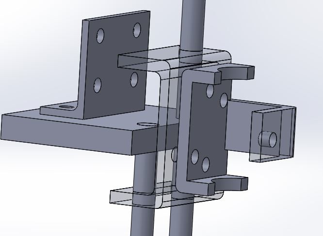
We designed the final drawbot in Solidworks and in Rhino, this way, the files are available in both softwares. We are designing a handler with two different positions depending on how we want to position the pen: perpendicular or oblique in relation to the surface we are painting.
We will add a stepper motor for a "pen up" / "pen down" function. The problem is that we will need to make some "tricks" because the stepper is a unipolar stepper motor (with the bipolars is easier to do it).
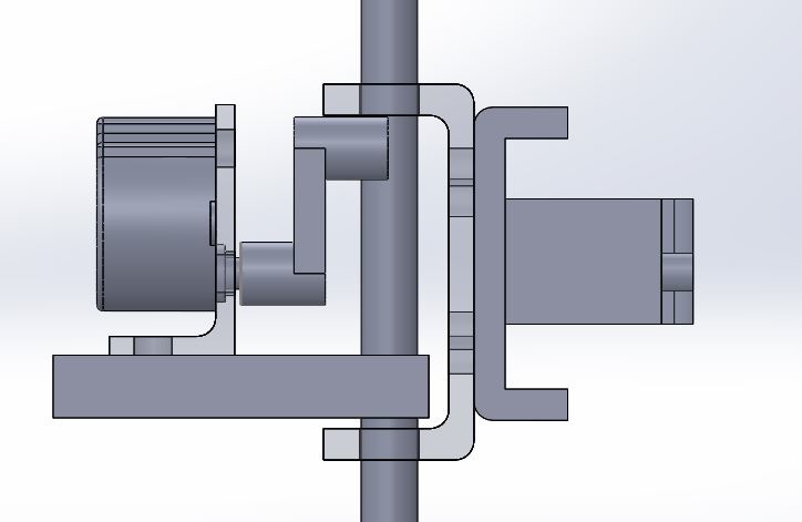
A simulation on how the pen holder works.
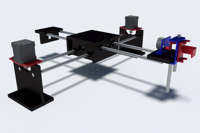
Here is a rendered image of how the machine looks like.
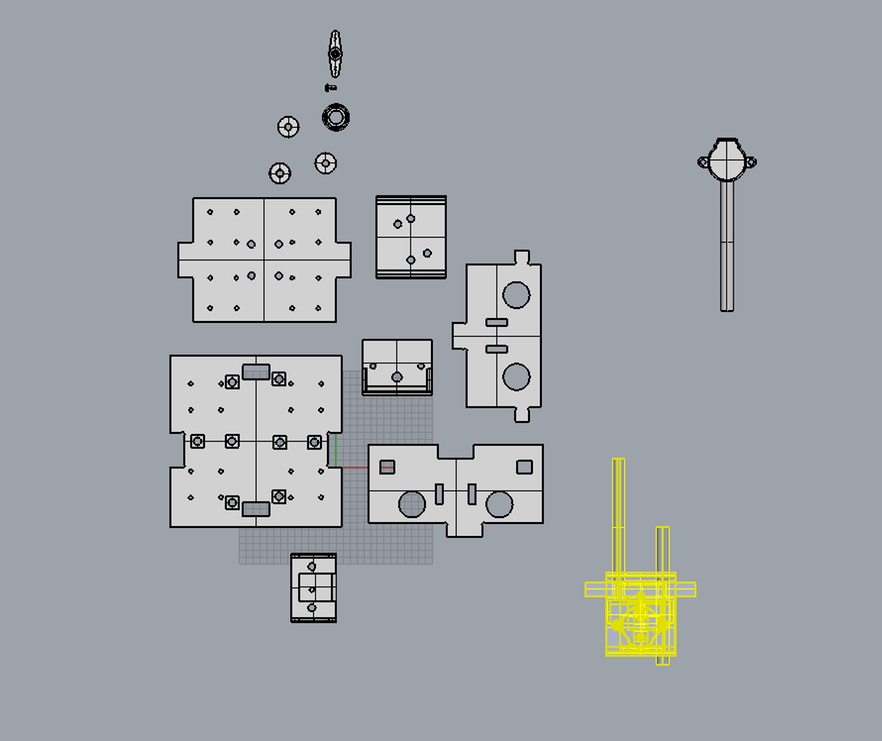
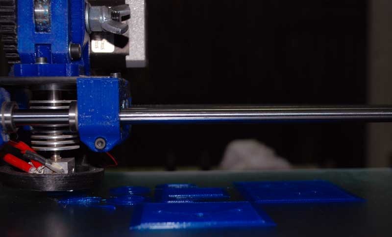
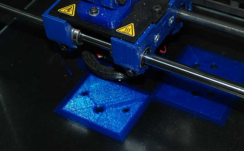
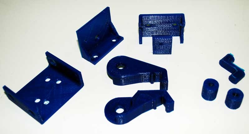
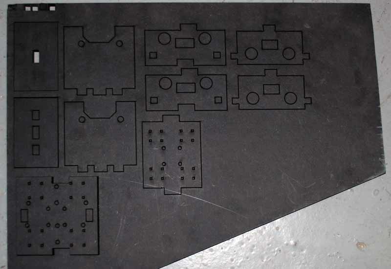
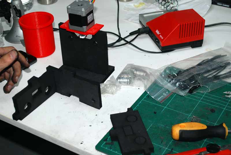
We 3D printed some parts for the final design.
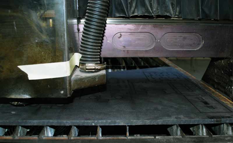
Some other parts were laser-cutted.
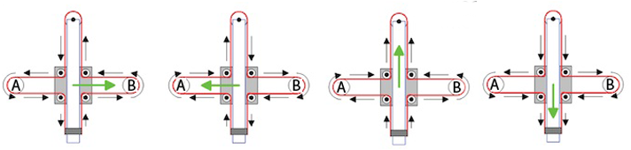
Mechanics
For the mechanics we had this references: Reference 1 Reference 2
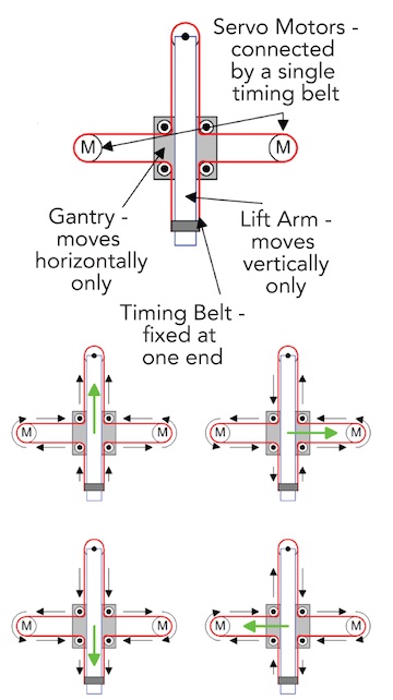
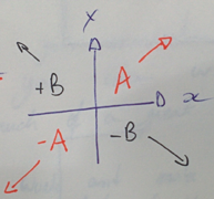
EQUATIONS OF MOTION A,B: motors
incX = 1/2(-incA-incB) this means diaA =incX+incY
neg_incX=1/2(incA+incB) this means neg_diaA= -incX -incY
incY=1/2(incA-incB) this means diaB=-incX+incY
negincY=1/2(-incA+incB) this means neg_diaB=incX-inxY
Useful links: Link1 Link2Programming
If you are new in Python:
Python introduction
1. Download and install Python:
-tip- you can download Python 3.x and/or 2.x ....install both versions and use the right interpreter depending of the project.
IMPORTANT!
pyGestalt only works with Python 2.x so for that project use it!
2. Download Python IDE or Python interpreter:
Options
Xavi's election Interpreter
3. Getting started:
-tutorials for beginners-
Python interptreter VS Python IDE (PyCharm). The interpreter is the command line in the Terminal. You can use it for programming. The PyCharm is an IDE for programming: supports listing all program files, syntax highlighting and other features.
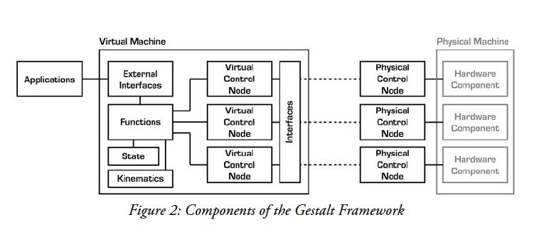
Gestalt is a control system framework for personal fabrication.
Two useful links for understanding the Gestalt framework:
Link1
Link2A step by step guide.
1. Download pyGestalt Framework and install it.
--> in the directory where setup.py is:
sudo python ./setup.py install
2. Programming the Gestalt Node with and AVR.
Why? -> The Fabnet to node connector is not typical!
-> Are nodes already programmed? Yes, we have it.
3. Download and Install pyserial -> order to talk over serial
-pySerial is a module to communicate python with the serial port ( Python Serial Port Extension ).
download from here.
installation guide.
sudo python ./setup.py install
- pySerial Documentation
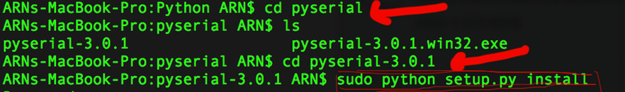
On Mac Os installing PySerial & pyGestalt from the Terminal:
1. Download and extract pyserial.
2. Navigate via Terminal to the folder you have pyserial extracted, in this folder you should have a file called setup.py
3. Run this script
sudo python setup.py install
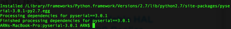
At the end of installation you should get a message like this:
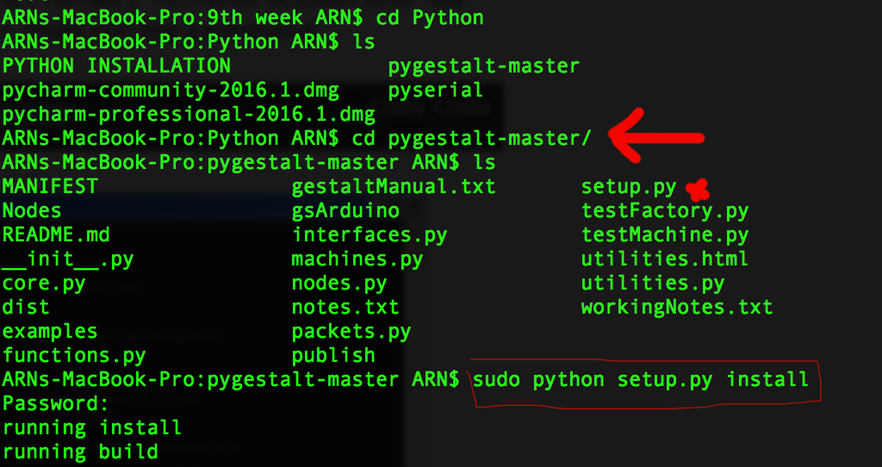
A similar process should be done for the pyGestalt
1. Download the Nadya Peek pyGestalt framework.
2. Navigate in the command line where your pyGestalt folder is located.
3. Run the command: sudo python setup.py install.
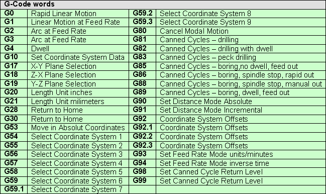
* Generate GCode thanks to this tutorial.
Main GCode commands.
Commands for XYCore Mechanics here.
Robopaint software for drawing robots.
Firmware used in a similar machine.
Arduino 2 axis GCode interpreter.
PNG -> GCODE
G-code is a language in which people tell computerized machine tools how to make something. The "how" is defined by instructions on where to move, how fast to move, and what path to move.
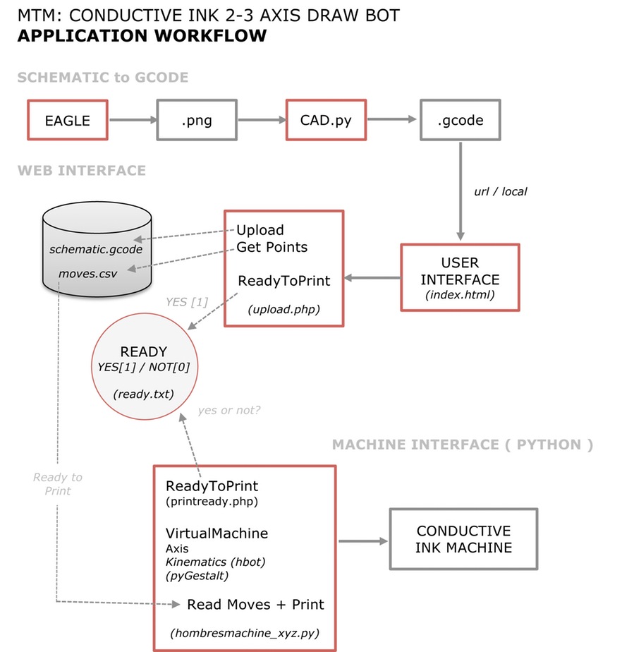
GCode specific codes.CoreXY workflow.
Files used
"code samples" are .png generated with eagle and .gcode files samples generated with cad.py
"gcode" gcode generator ( cad.py )
"machine app" files for the machine application
"web" files for user interface and .csv generator
PNG - GCODE
G-code is a language in which people tell computerized machine tools how to make something. The "how" is defined by instructions on where to move, how fast to move, and what path to move.
Specific Codes here
Gcode generators here
CAD.PY
cad.py is a single-file script by Neil Gershenfeld, capable of creating GCode files for isolation milling and drilling.
Sourceforge cad.py files here. Library dependencies here
. Numpy Github here
. pip install numpy -> If you have pip installed
sudo python setup.py install -> in the numpy folder
sci.py:
Tutorial on how to use cad.py here.
Functions we use to generate .Gcode:
1) When select Gcode format, prepare the output file and necessary parameters
2) Read png and generate gcode file format
Support on CoreXY Programming used in GBRL here.
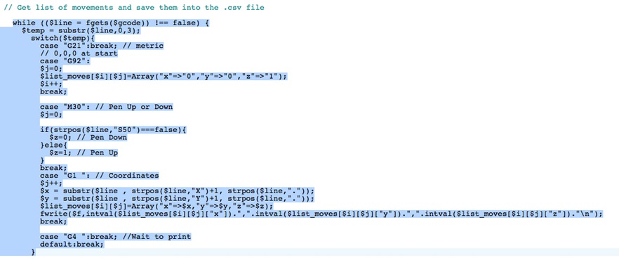
Generate movement list from gcode.
We used PyCharm for comunicating with the gestalt nodes.
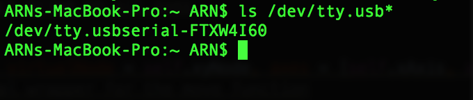
First, we need to know our USB "name", we chek it on the command line.
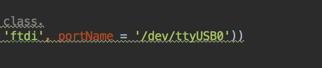
Then, we enter the port name on the .py file.
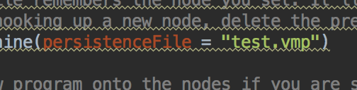
Finally, we delete the test.vmp file and run the code.Electronics
Link1
Motor board files:
Link1
Link2
Motor Board used in Axibot:
Link1
Hardware:
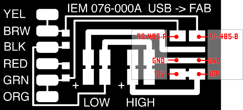
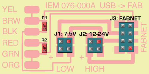
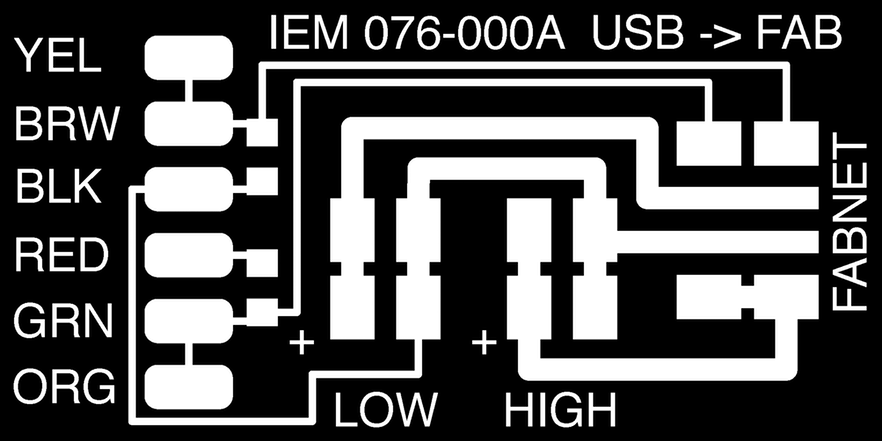
For the electronics, we need to mill the FabNET board to use it with RS-485 usb connectors:
Fabnet is a multi-drop network, meaning that multiple modules (a.k.a. nodes) share a single set of communication wires. Signalling is differential based on the RS-485 specification. Each node is assigned a four-byte IP address which uniquely identifies it over the network.
Fabnet provides power at two voltages: high voltage (12V - 24V) is intended to drive motors, lamps and actuators, while low voltage (7.5V) supplies power to the logic circuits of the nodes.
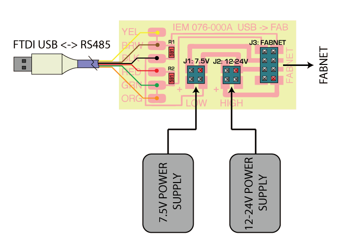
Establishing connectivity between nodes and a computer, and providing proper power, requires several components: high and low voltage power supplies, a USB-RS485 converter cable, and an adaptor board (076-000A) with bias resistors.
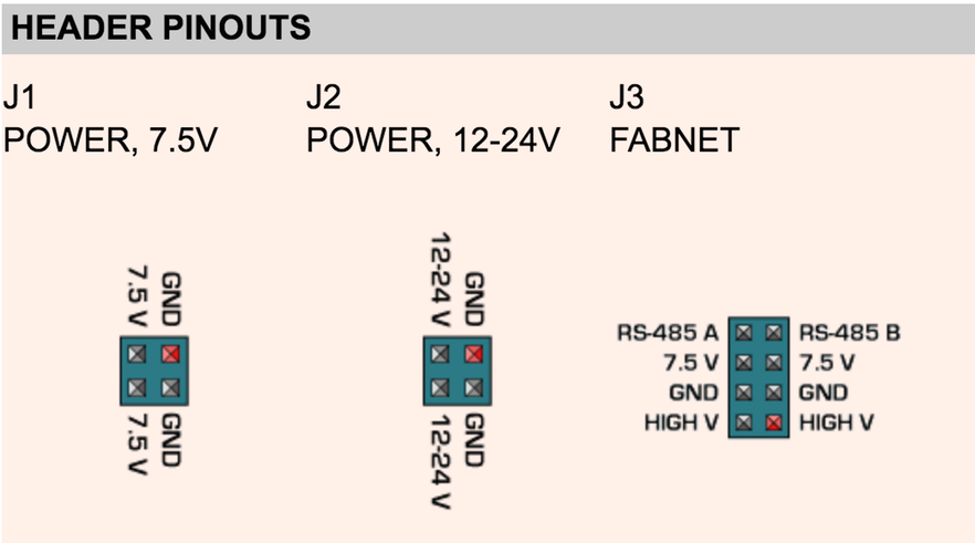
The next images are some diagrams to understand how the FabNET connects to Gestalt boards and power supply.
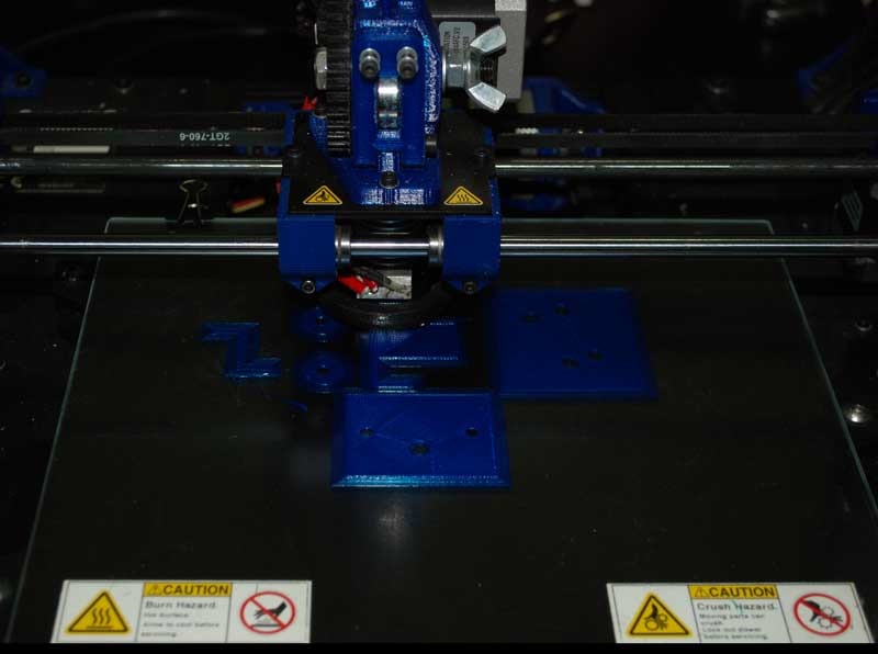
The machine working for the very first time.
Download the files here