Computer-Controlled Cutting
Assignment:
1. Make the FabISP in-circuit programmer.Mill the board.
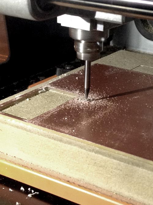
This week we started our assignment milling the copper board with a Roland SRM-20 using the site fabmodules for creating the .rml file loading a .png file.
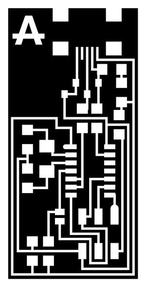
First, we sticked the copper board to a wood base and place it into the milling machine. It is very important to try to be as precise as possible. Trying to stick it parallel and equidistant from the wood edge.Second, we need to load the fabmodules site, from there we used the .png files to create .rml files for milling the board according to the .png file drawings.
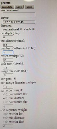
We click on the image tab, select image.png, then select the SRM-20, set the x y and z values as 0. Click on process tab, select Roland Mill 1/64. An set the values for milling. For the engraving process we use the 1/64 mill bit.
Air cut: 1/64 mill bit / depth:0 / offset:1 We click on calculate and save the .rml file
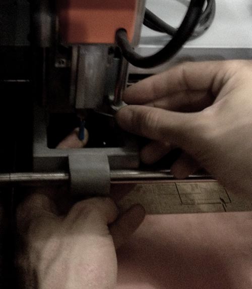
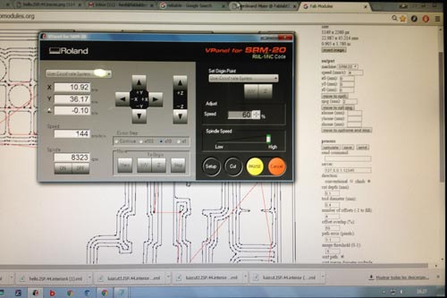
From now on we need to be very precise, moving the mill bit at the x and y position with the milling software. Now, we can save the x and y position. Once we have the mill bit in place, we must unscrew the mill bit and make it touch gently with the board. Finally, we save the z position.
Again on the computer using the milling/printing software we select cut, load the .rml file and cut.
We repeat this process for engraving the circuits, loading the circuits .png file. With the next values: 1/64 process mill bit / depth:0.1 / offset:4.
Once we are done woth the engraving, we should change the mill bit to 1/32, for making the cut, the process is the same but with this values
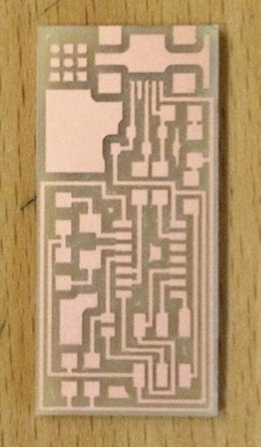
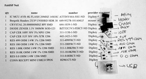
1/32 process mill bit / depth:0.5 / offset:1.Once the board is milled it's time to look for the components.
With al the components gathered together it's time to do the soldering process.
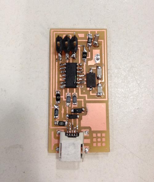
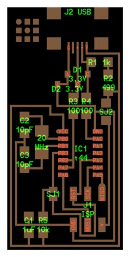
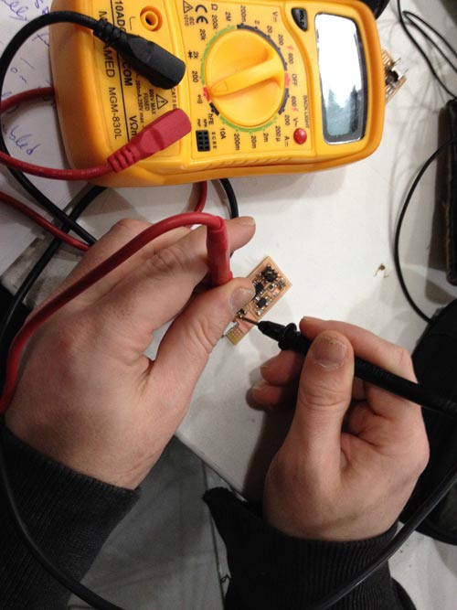
Soldering can be tricky so you need to take your time, all the process took me two hours and a half. The idea is to make smooth and shiny solder joints. I started with the USB connector and from the smallest ones to the biggers. Trying always to do first the components placed in the middle, leaving the components on the edges for the last. I used Neil's design. Here is the result.Before plugin the board to the computer we should check for correct conectivity. The metrometer should beep when the two elements are connected, for example GND to GND. We must check all the board components to ensure that according to the circuit schematics every connection is correct.
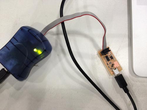
Now it's time to plug it into the computer and check if the board is reciving power from the computer. We are using the programmer to first check the connectivity. I've got the Green Light at the first try!
Next step is with the programmer plugged in begin to program the board.
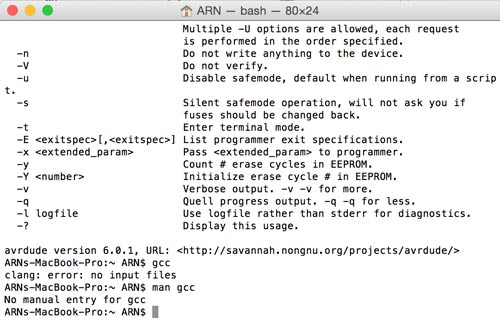
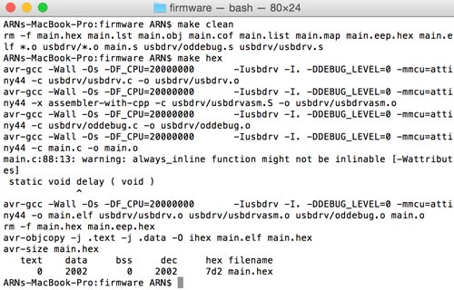
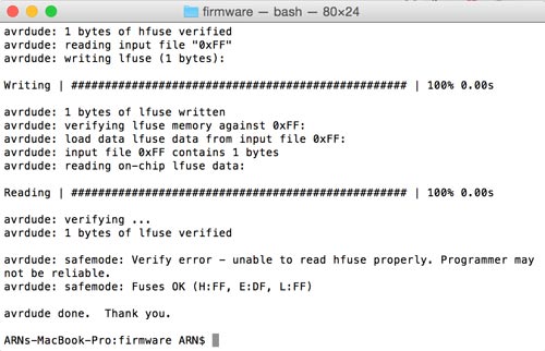
I followed this tutorial
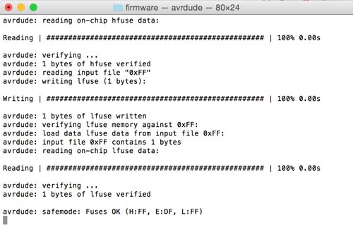
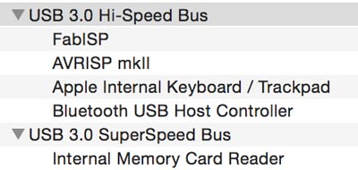
First, you need to download the FabIsp firmware, unzip in the Desktop. Navigate on Terminal to the FabIsp firmware folder. Since I'm in Mac OS I launched the Terminal and typed these commands: make clear (to delete everything en your board), make hex, make fuse and make program. This is the process of compiling and loading the libraries we are going to use into the board. We have just made a board for programming other PCBs.I checked the system preferences if the system detected the board.
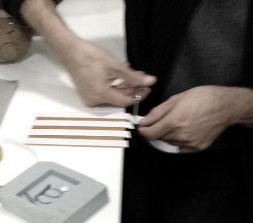
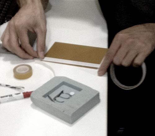
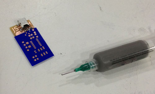
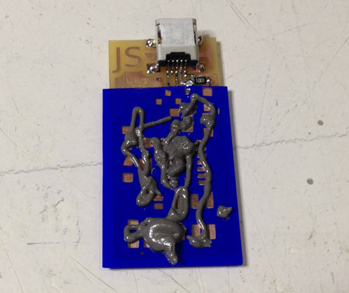
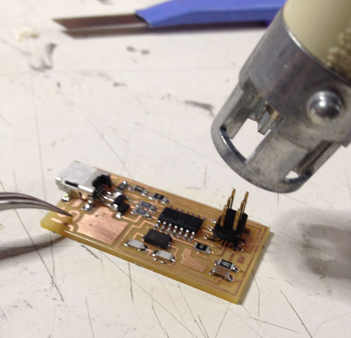
Finally, assisted by Ferdi, one of our instructors, I made a second board using solder paste, just for the fun of it.
First, you need and stencil of your board. I made it with the laser cut.
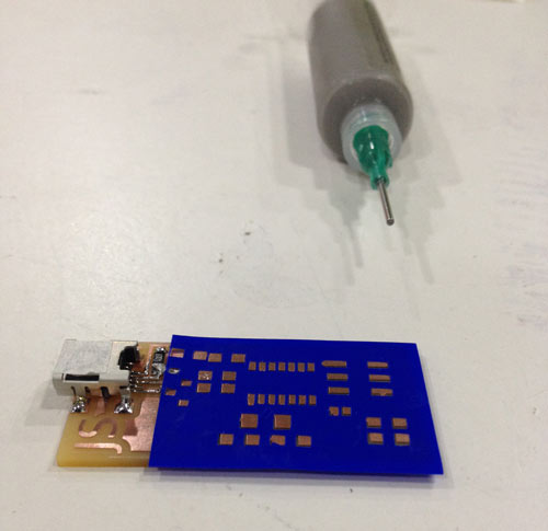
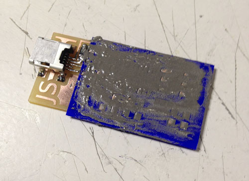
Place the stencil on your board.
Apply the solder paste.
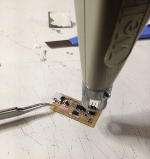
Place the components on the top of it.
Apply heat with the heating gun.
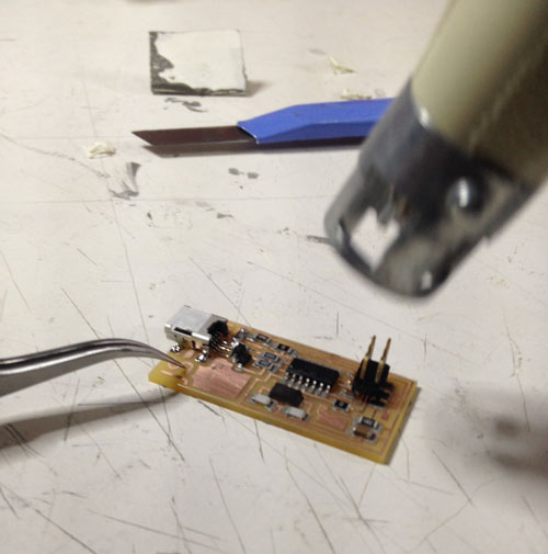
We are supposed to remove the 0.0 OHMS Resistors once the board is programmed, but I will let them attached to the board until next electronics assigment. Great! Looking forward for the next week assginments and lectures ;)Download the files here