-1984-
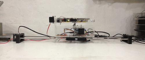
3 axis social / tracking / smart camera.
The project is divided in 3 areas: Design / Electronics / Code
The development is based in parallel process and spiral development. Instead of finishing each area and go to the next, the work is done at the same time in the three areas, based on the idea of small iterations on each area. Using this method we can fix and debbug problems and errors before a big step in another area has been done. The downside of this method: is difficult to see results, at least during the first stages of the process.Design.
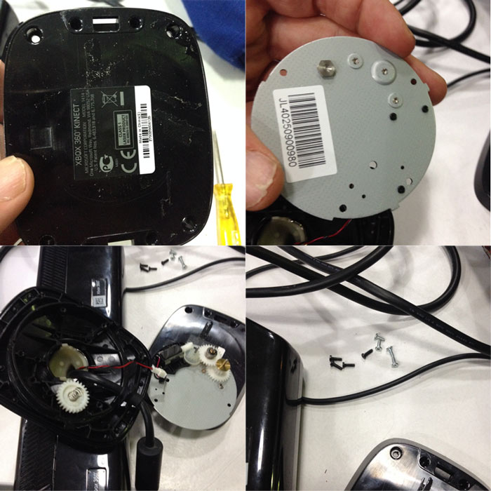
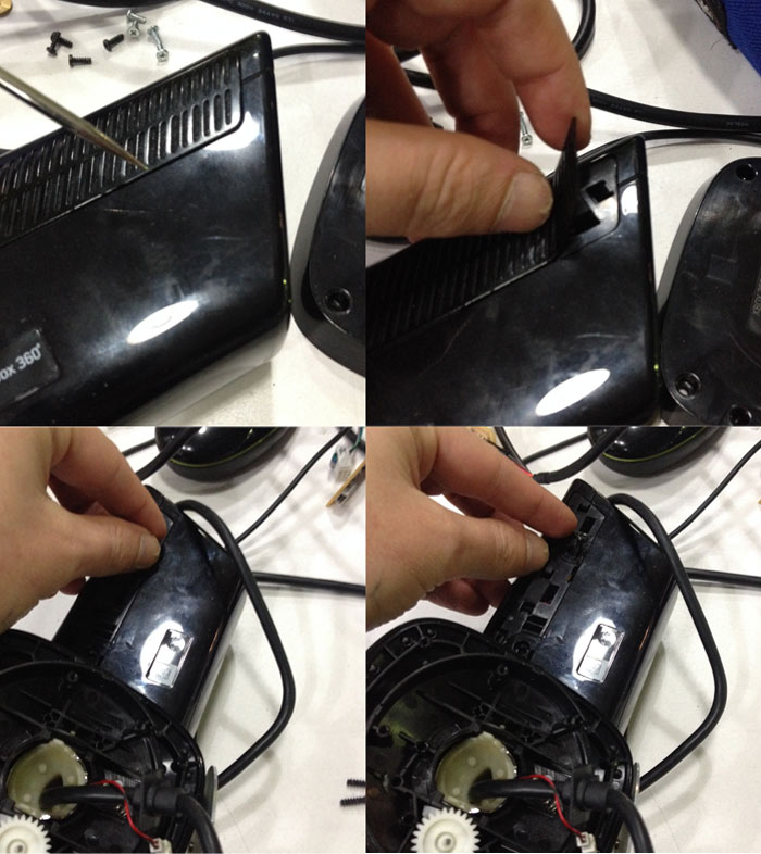
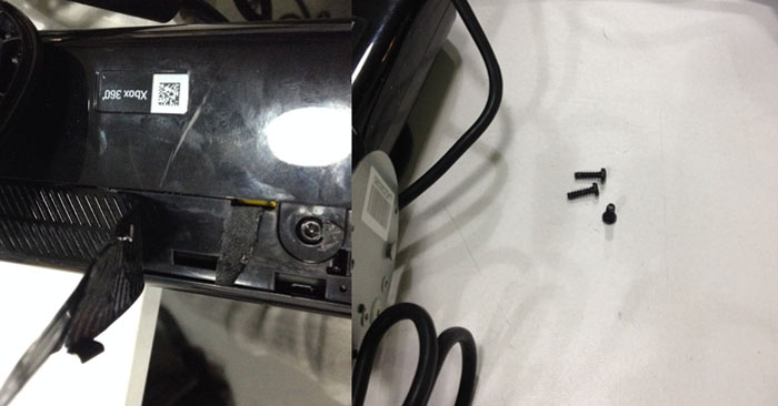
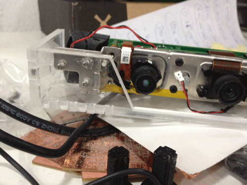
The first step was to hack the Kinect. I bought a second-hand one, really sheap (15 €, for the model 1414)
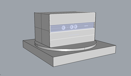
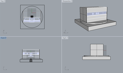
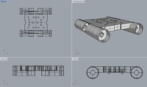
With the Kinect I decided to get rid off all the unnecessary material: plastic casing, support base... and keep only the electronics.The kinect have 4 microphones I got rid off those as well. With only the electronics I can start the design process. Taking in consideration the size of those components. For designing the machine design I used Rhinoceros. Starting from sketching ideas, how the machine will be supported. This first idea is based on a cube shape. The problem is that it just need one axis and I eager to use at least 3 axis. At this point of the design process I consider the shape so blocky, and with not enough design process.The next step is to think how this blocks can move along different axis. I started a new design thinking on how to improve this mechanical requirements.So far I managed to add new axis to the machine, but I'm not yet satisfied with the shape. So I decided to try to combine both designs.
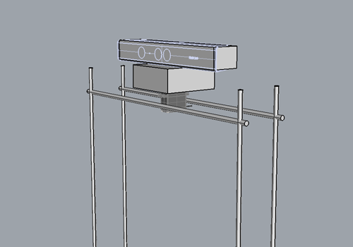
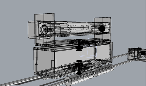
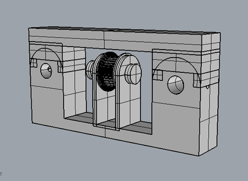
The next image shows the parts that still have a problem. As you can see, because the design has a top part the kinect cannot be rotated. In the horizontal axis, because the base of the whole structure is not enough big to support the whole structure.
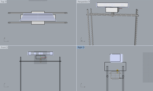
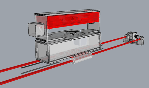
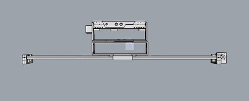
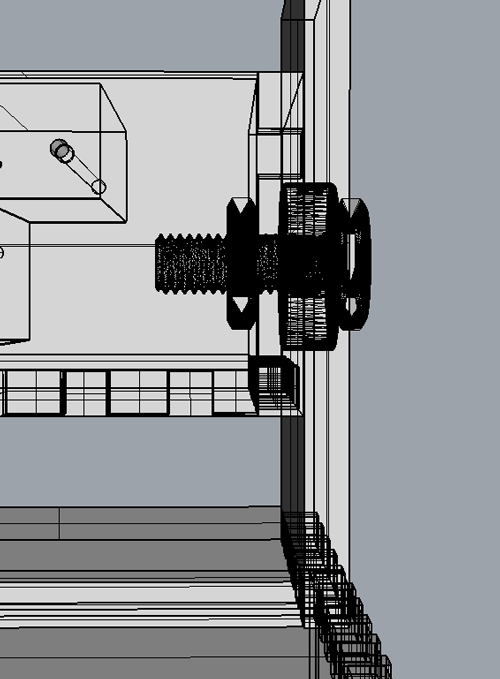
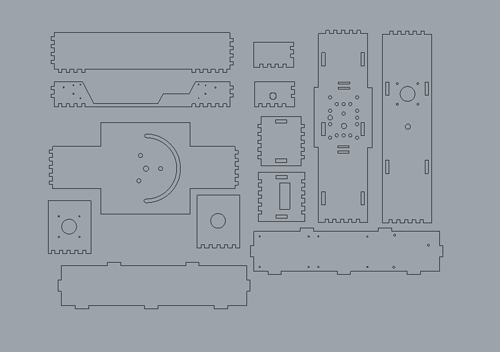
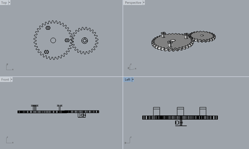
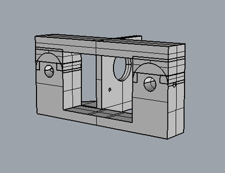
At this point I was thinking on 3 steppers, but later I changed my mind and used two steppers and a servo.The next image shows the design without the top part.Here is the machine's final design. At this point I didn't had decided yet use a servo for the top part. But the I added more supports for the base where I will put the linear bearings.Some design, details. Such as, press-fit, bearings, screws, gears...Once I was happy with the 3D design I converted the 3D shapes into 2D drawings with the Make2D command, pretty useful for lasercutting all this shapes.For the 3D printed shapes I exported them as .stl file, after making boolean operations with all of them. It is important to have the shapes into one single shape.
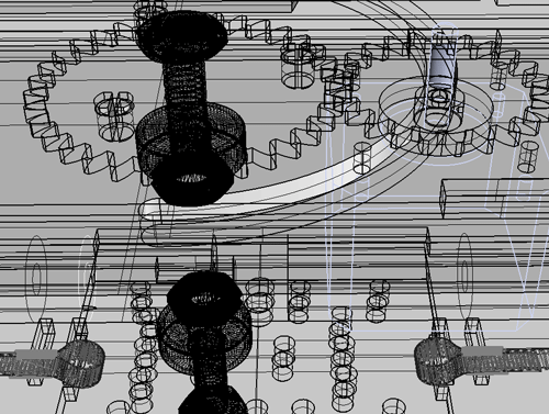
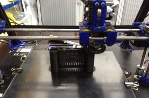
The gears.The base supports.The main support with the holes for the linear bearings and the rods.Next step was printing and lasercutting the different parts.The password for the video is fablab 3d printing video.
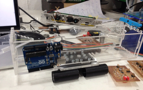
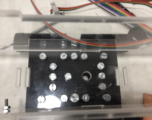
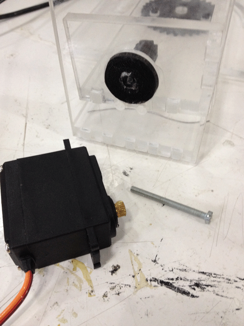
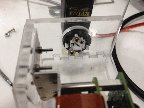
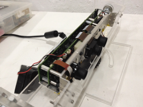
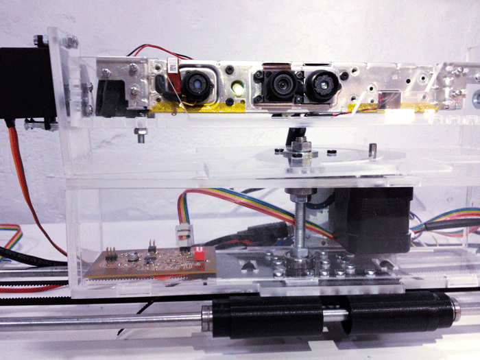
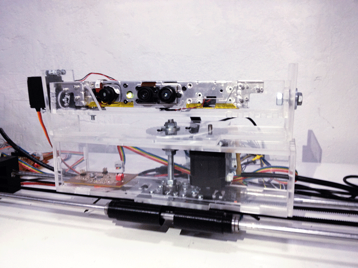
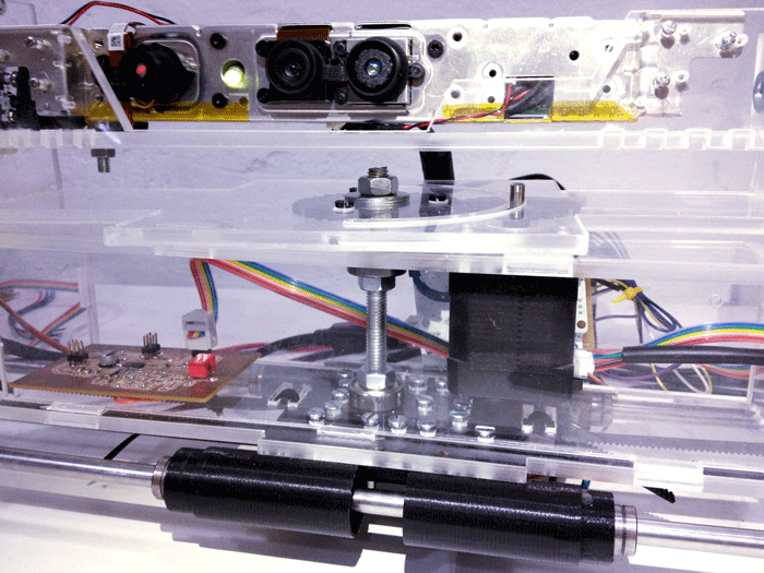
With everything on the top of the desk I started assembling the whole machine.The mechanism I designed and 3D printed didn't worked as expected...Thanks to my classmate Luiz he helped me on how to attach the servo in a proper way, no extra mechanisms where required.Electronics
I started the electronics area together with the programming area.
The idea was to test different motors with the arduino, the Kinect and processing.
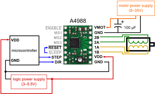
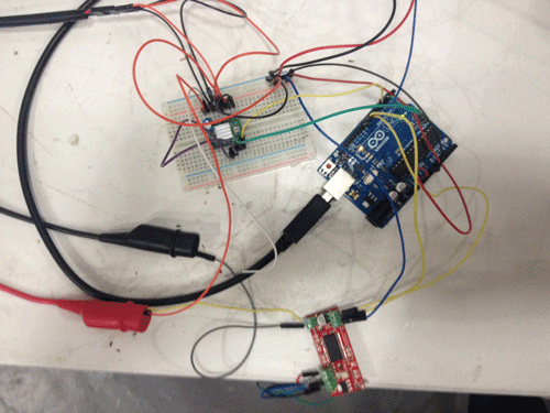
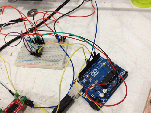
The next image shows how the Pololu bridge boards are connected to the stepper motors.
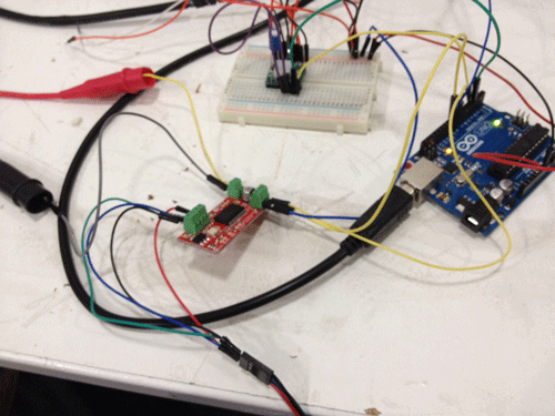
How to connect the pinout to the Nema17.
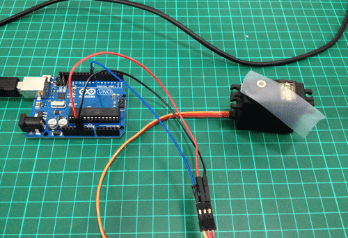
The next image is a little bit tricky because you should know that RESET and SLEEP need to be connected.How to connect the Pololu driver and the stepper motor.This is the easy part, a servo can be connected directly to the Arduino board, you don't need a bridge.The password for the video is fablab
Here is a video testing the servo motor.
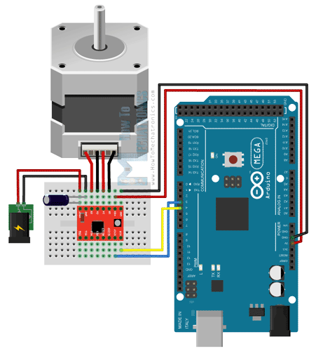
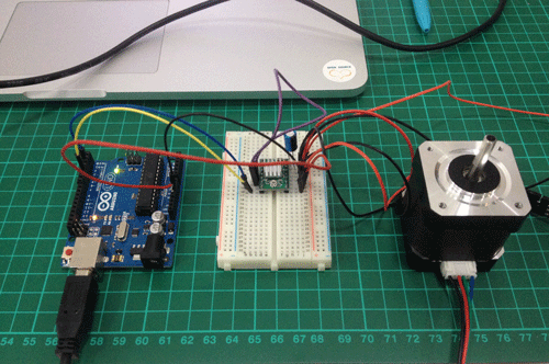
I wanted to understand how the Pololu and Easydriver work with the Arduino. Using a breadboard I connected them to the Arduino in order to understand the pinout and how the connexions need to be done. The next videos show the motor testing and the process of understanding the comercial bridge boards understanding.The password for the videos is fablab
Test motor 1 video
Test motor 2 video
Test motor 3 video
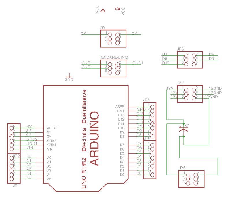
Once I made the tests I started to design the bridge boards in Eagle. I decided to use an Arduino Uno board and make the shields (instead of usign the Pololu or Easydriver). The research for my electronics design included:
FabInABox
Gestalt nodes
microduino
jaredwolff
melzi
codlink
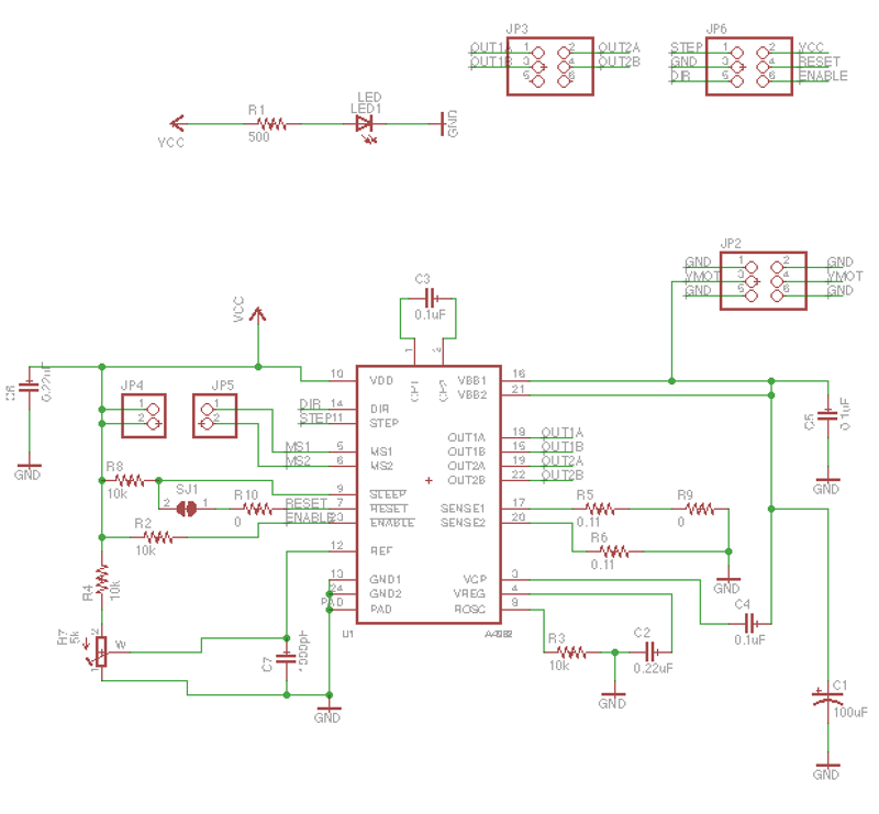
I wanted to use the A4982 driver beacuse it can be used in microstepping mode.
Then, I decided to start with the Eagle designs.
Here is my Bill Of Materials:
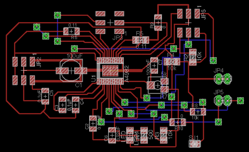
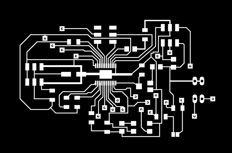
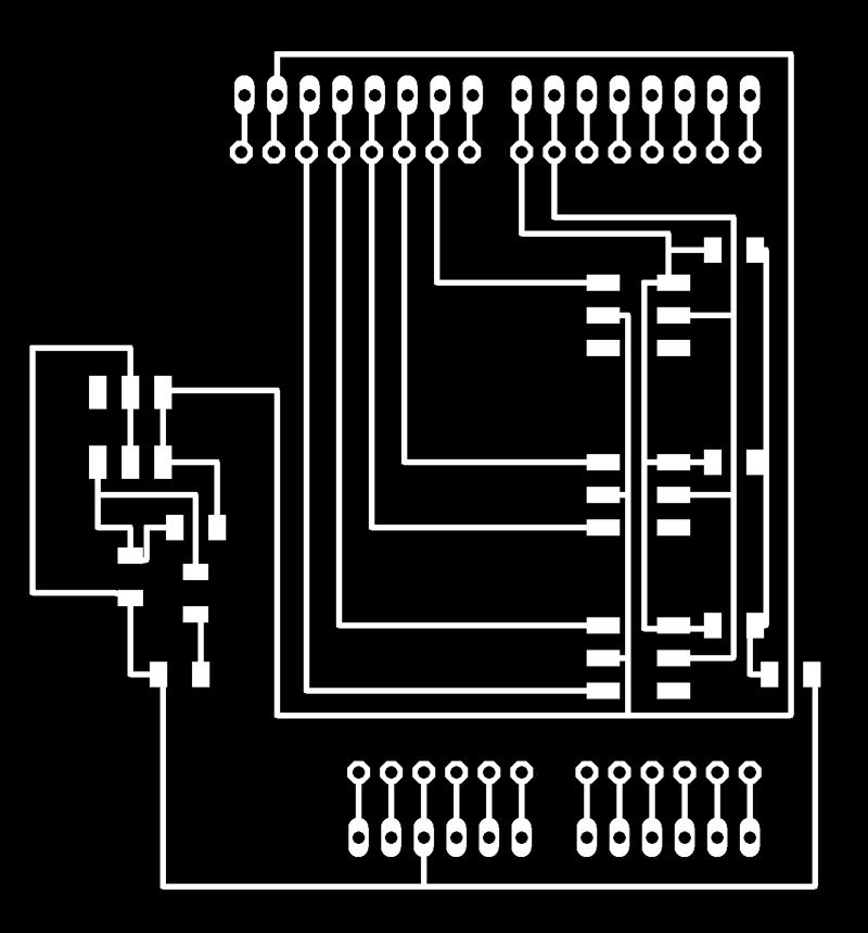
Part Value Device Package Description C1 100uF CPOL-US153CLV-0605 153CLV-0605 POLARIZED CAPACITOR, American symbol C2 0.22uF CAP-UNPOLARIZEDFAB C1206FAB C3 0.1uF CAP-UNPOLARIZEDFAB C1206FAB C4 0.1uF CAP-UNPOLARIZEDFAB C1206FAB C5 0.1uF CAP-UNPOLARIZEDFAB C1206FAB C6 0.22uF CAP-UNPOLARIZEDFAB C1206FAB C7 1000pF CAP-UNPOLARIZEDFAB C1206FAB JP2 PINHD-2X3-SMD 2X03SMD PIN HEADER JP3 PINHD-2X3-SMD 2X03SMD PIN HEADER JP4 PINHD-1X2 1X02 PIN HEADER JP5 PINHD-1X2 1X02 PIN HEADER JP6 PINHD-2X3-SMD 2X03SMD PIN HEADER LED1 LED LED LED1206 LED R1 500 RES-US1206 R1206 Resistor (US Symbol) R2 10k RES-US1206 R1206 Resistor (US Symbol) R3 10k RES-US1206 R1206 Resistor (US Symbol) R4 10k RES-US1206 R1206 Resistor (US Symbol) R5 0.11 RES-US1206 R1206 Resistor (US Symbol) R6 0.11 RES-US1206FAB R1206FAB Resistor (US Symbol) R7 5k RTRIM-ST-4EA RTRIM-ST4ETB R8 10k RES-US1206FAB R1206FAB Resistor (US Symbol) R9 0 RES-US1206FAB R1206FAB Resistor (US Symbol) R10 0 RES-US1206FAB R1206FAB Resistor (US Symbol) SJ1 SJ SJ SMD solder JUMPER U1 A4982 A4982 TSSOP-24 Because I had so many connexions I decided to use two layers and vias. For the blue traces I made the conexions with wires instead of milling a double sided board.
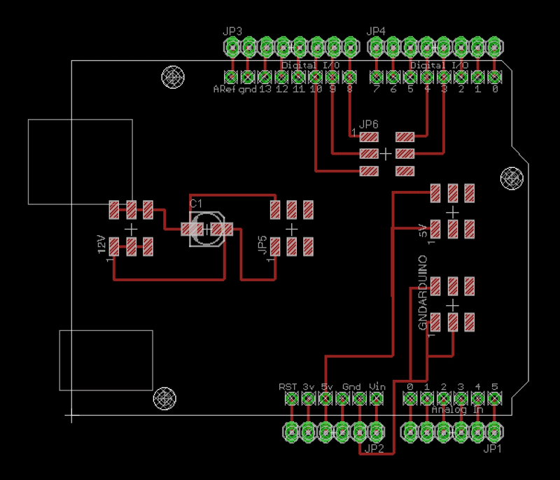
I also designed a shield for Arduino in order to plug all the connexions to this shield insted of using a breadboard.
This is the Bill Of Materials for my shield:
Part Value Device Package Description 5V PINHD-2X3-SMD 2X03SMD PIN HEADER 12V PINHD-2X3-SMD 2X03SMD PIN HEADER C1 CPOL-USSANYO_SMD_B6 SANYO-OSCON_SMD_B6 POLARIZED CAPACITOR, American symbol GNDARDUINO PINHD-2X3-SMD 2X03SMD PIN HEADER JP1 PINHD-1X6 1X06 PIN HEADER JP2 PINHD-1X6 1X06 PIN HEADER JP3 PINHD-1X8 1X08 PIN HEADER JP4 PINHD-1X8 1X08 PIN HEADER JP5 PINHD-2X3-SMD 2X03SMD PIN HEADER JP6 PINHD-2X3-SMD 2X03SMD PIN HEADER U$2 ARDUINOUNO ARDUINOUNO ARDUINO Arduino Diecimila/Duemilanove In order to know the distances for the pins I used the Arduino Uno object in Eagle, this way we easly be sure that we place the links where they should be.The password for the video is fablab
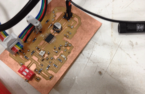
Here is a video of the milling process.
Code
This is the last of the section, but the process has been in parallel working at the same time in the different areas. So first I tested simple examples with the arduino libraries making the motors work: I used a Nema 17 stepper motor and a Tower Pro 995 servo motor.
The servo is pretty straight forward. You don't need any library neither any bridge board just 5V, GND and an Arduino pin.
For the Nema 17, though, you can use different libraries I tested the Servo.h and the AccelStepper.h
I started with this simple stepper example:
In Processing I used: processing.serial in order to get the data from the serial port where the kinect is connected. And the SimpleOpenNI for using the data the camera and sensors from the kinect are adquiring.
The workflow for coding was more difficult than I expected. I started with the motor movement in Arduino. Once I had the motors moving I started with the Processing code.
My first step was to control a servo motor moving with a simple interface on processing using the mouseX coordinates.
Here is the code I used.
The password for the video is fablab
Testing the servo video.
The problem with libraries is that you need to understand how the library works and what does it do... and sometimes the documentation is not good enough, some parts missing... so, instead of trying to understand a complex library and work with it I decide to go with the Servo.h library and program with a simpler code.
This is the Arduino code for controlling one servo and two steppers and gather the visual data from the serial port that processing sends. At this point the motor movement is quite smooth. I'm happy how the motors move.
This is the Processing code, for the kinect detection and send the data through the serial port.
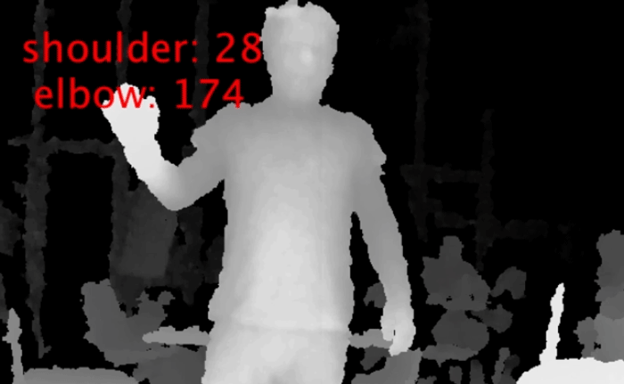
This is the feedback you got when you run the Processing file.
I'm still having some problems with the blob detection. Maybe a future iteration could be to use skeletons instead fo blob.
The problem is that it is really slow, and sometimes the tracking is lost.
Besides is better to use the kinect and the person to be detected to be in a white, clean background without visual noise. Then is easier for Processing to detect the person.Thanks to:
Neil Gershenfeld
Nadya Peek
Ferdinand Meier
Santiago Fuentimilla
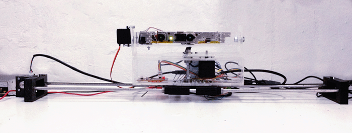
And all my classmates during this FabAcademy 2016The –1984- tracking device.
The video for the final presentation with the machine working, at this point the movement still was a little jerky.
The password for the video is fablab
Download the files here