Week 11: Input Devices
Task
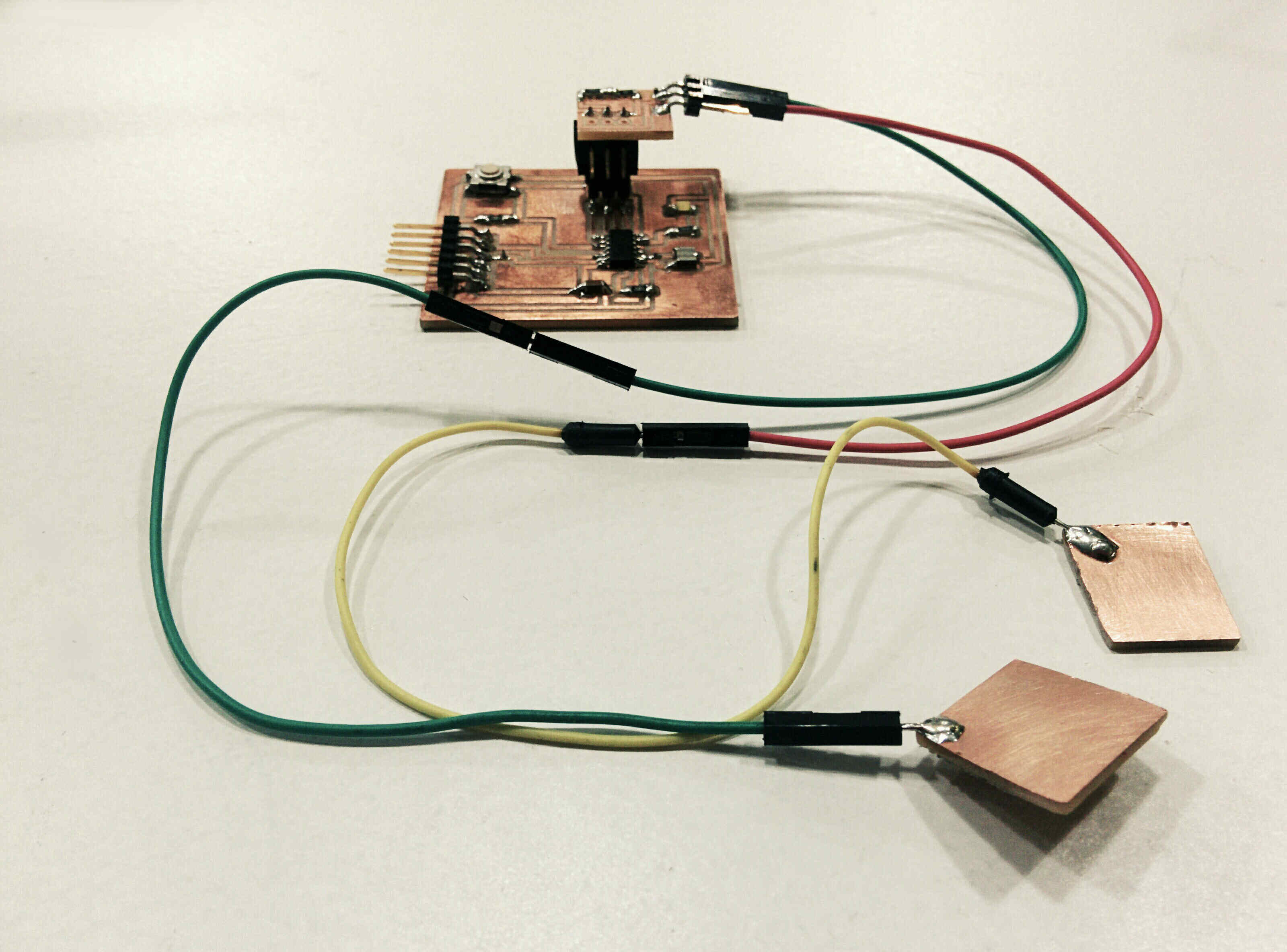
Measure something: add a sensor to a microcontroller board that you have designed and read it. For my final project I will use a "galvanic" skin sensor to measure electrodermal activity (EDA). This week´s assignment is my experimentation for the final: as I have missed six weeks of Fab Academy (most of them electronics!), I am actually catching up now, close to the final deadline, fullfilling assignments in a way that that will teach me to get the final project right. So, I made a tiny shield board, which goes on top of my previously designed hello world board. The sensor consists of two small cupper boards which connect to the shield with jumper cables.
References
* Here is the content page and Neil´s lecture video.
* AtTiny44 DataSheet
* Inspiring project: "Stress" Makes Art - A Galvanic Skin Response and Visual Generation
* Galvanic Skin Response prject
* "truth sensor" prototyping
* High Tech Low Tech: MIT Media LAb Research Project with a tutorial on how to program ATTiny with Arduino.
* MIT student Ani´s How To- documentations are a fantastic ressource.
Components
* 2 x resistors: 499k and 0.
* 1 x AVISP
* 1 x header with two pins
* Galvanic skin sensor: two cupper boards & two jumper cables
Process
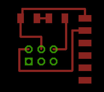
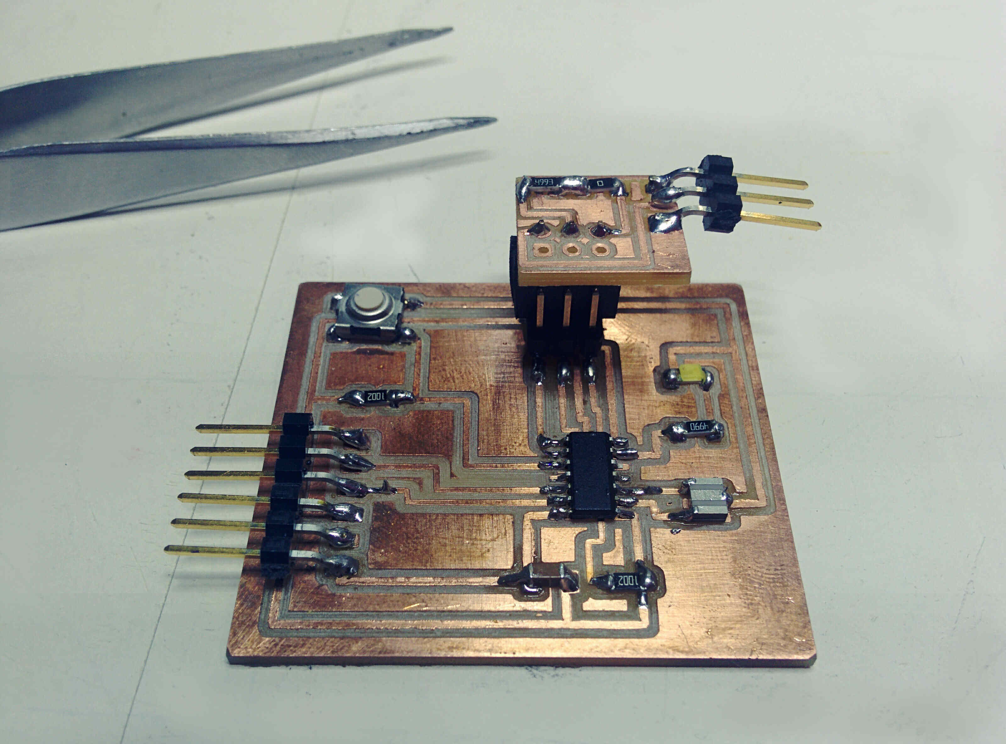
I did not plan to make a shield, but to connect the two boards via the rainbow cable. This is the nicer solution though. I could just have prototyped the sensor by connecting my hello world board to a breadboard. However, as I want to improve my Eagle, milling, soldering basics (and also realise this assignment), I made an actual board.
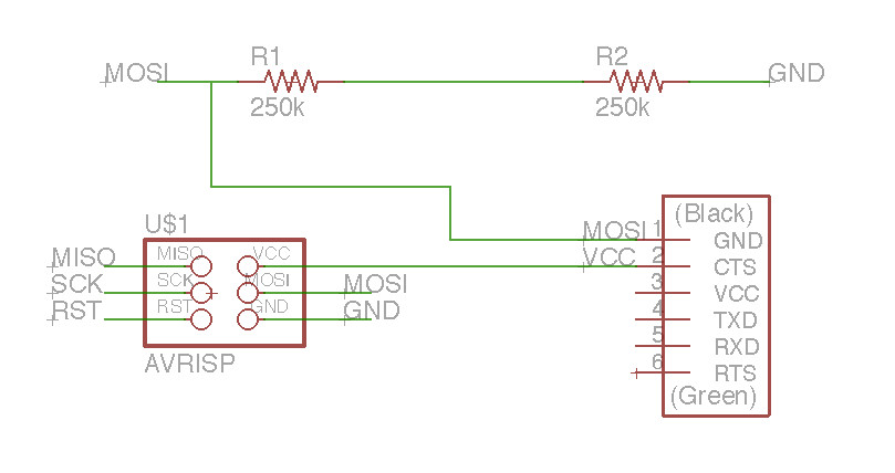
I wanted to use two resistors a 250k connected in series. As we didn´t have them in the Lab I used the 499k and a zero resitor instead. For the skin sensor a sensitive resistor is needed. The sensor is very simple: two cupper boards on which I soldered the jumper cables. One could also use two hex nuts instead of the cupper boards. The cables connect to the header: one cable connects to VCC (5V from board), the second wire is connected to GND through two 250K resistors in a series. This second sensor's wire is also connected to the Mosi on the hello world board.
Sensor
Programming: Arduino & GTS Sensor
code it, program board, connect sensor, run it
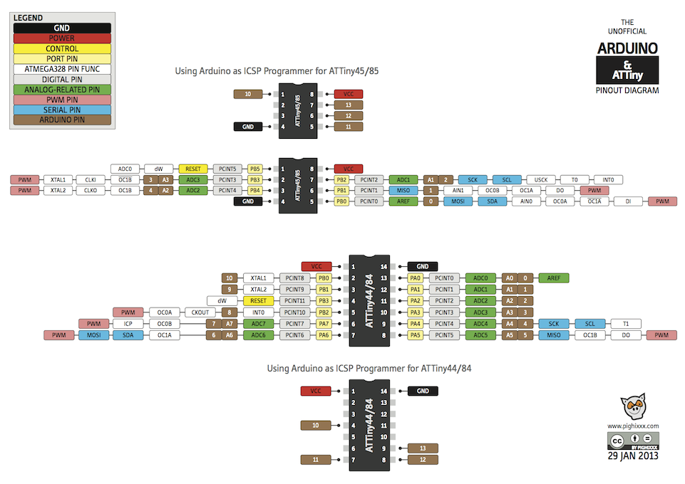
I used this code to run in the arduino software. next I translated the arduino pin definitions for the LED and the GTS to my hello world board.

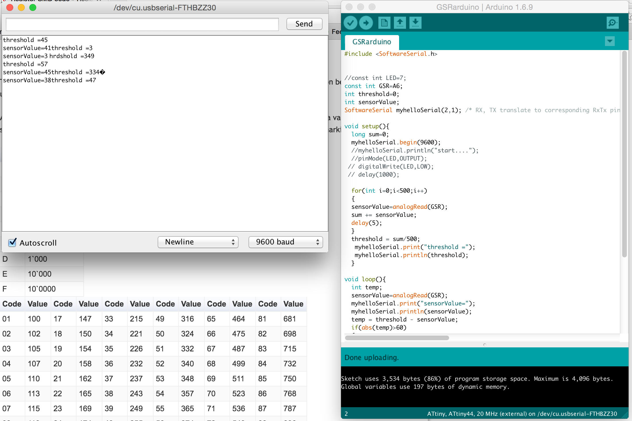
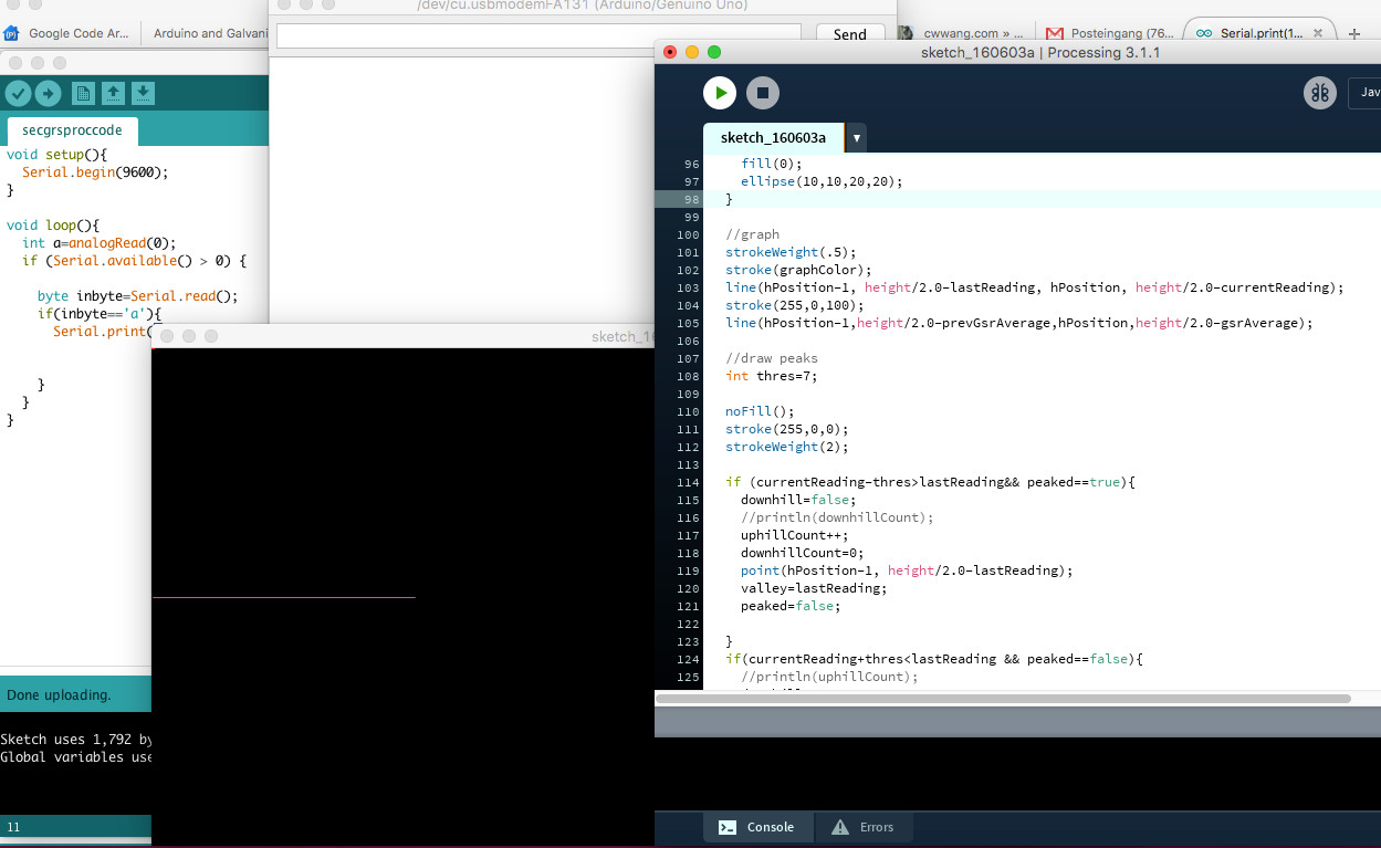
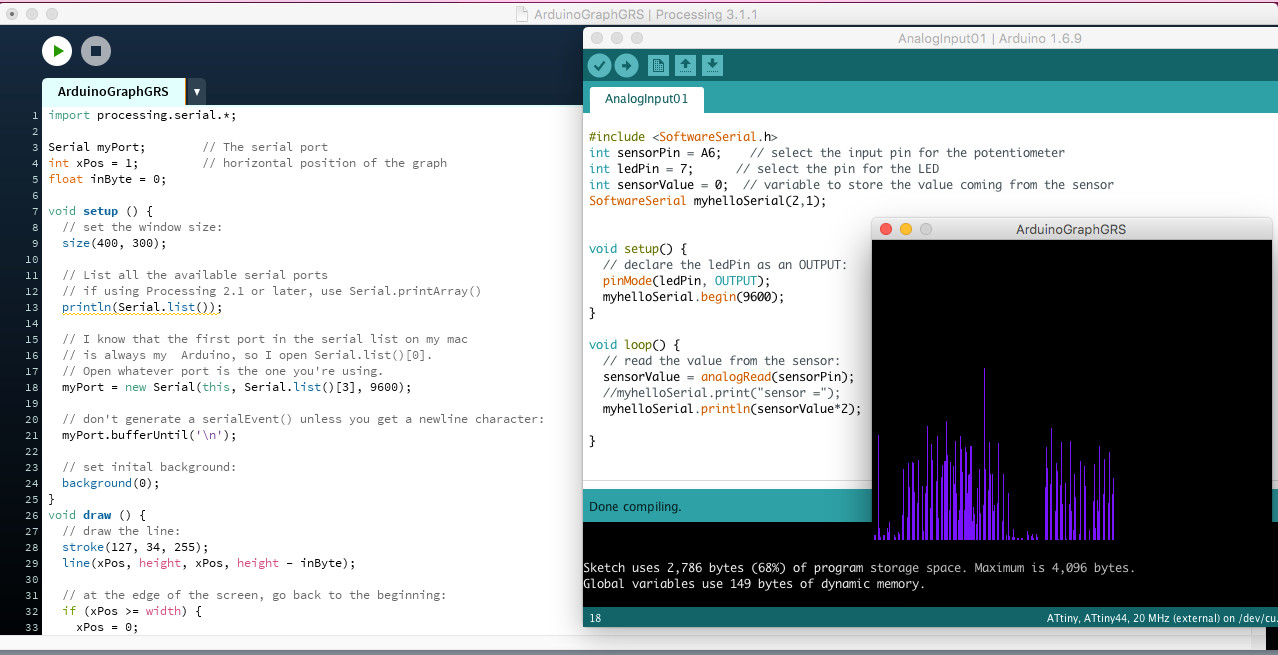
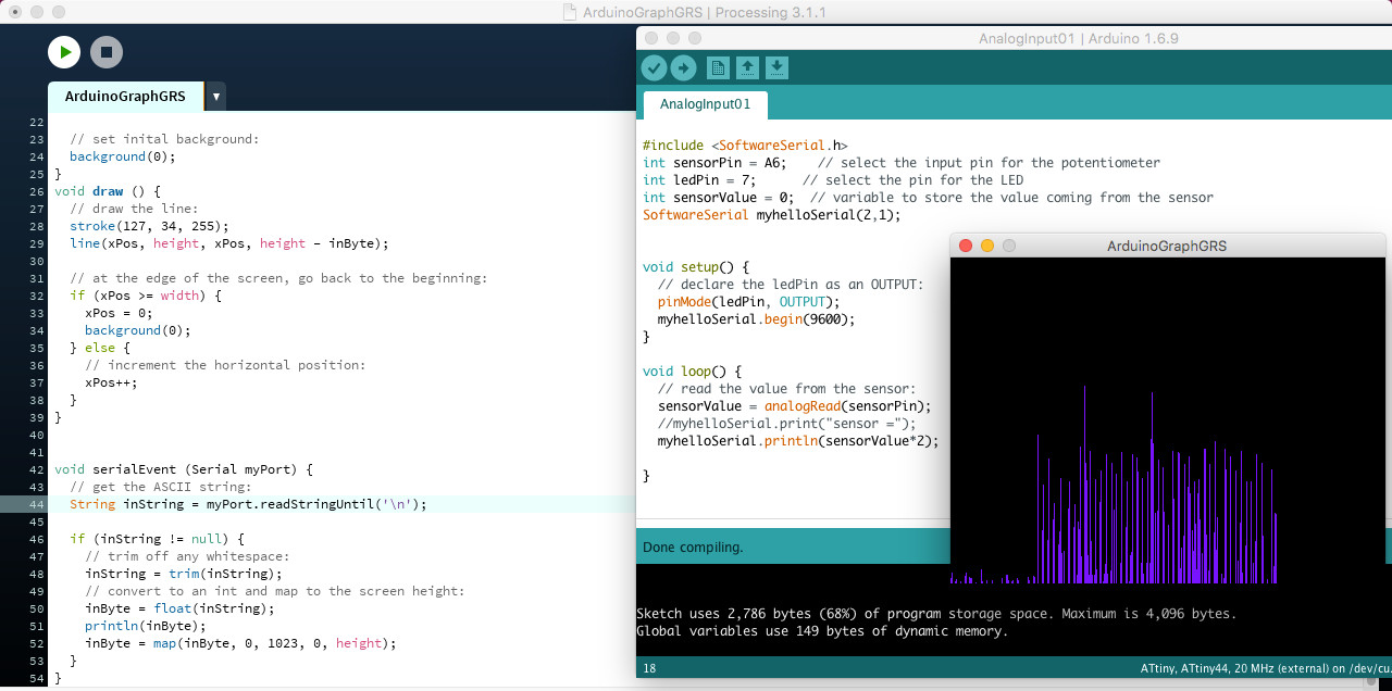
Next I had to correct the serial communication. I copied While hardware and code seemed to be correct, I arduino gave me warnings. The serial monitor displayed values when the sensor was not attached, but it only showed sensor values once. We tried to run the set up on Santi´s computer and here it worked. However, the sensor values detected didn´t seem to be meaningful. Angel - one of IAAC´s electronic and programing experts, also well experienced with Arduino, said it´s a conflict between libaries related to the BIN definition (this forum discussion helped). As he didn´t have time to do much troubleshooting, I was quite at a loss of what to do next. Next: connected the hello-world & sensor set up to an ardunio instead of my hello world board on Santi´s computer. here values showed in serial monitor made more sense. however, I had doubts from the beginning about the code as it was for a project utilising arduino GSR component Grove. So, instead I try this code now, which combines arduino with processing. As I want to use processing for my final project, it´s a good try out anyway. Connected arduino uno to my sensor instead of my hello world board, copied suggested code into arduino / processing respectively. Original arduino code reads "Serial.print(a,BYTE);" which is no longer supported. Needs to be replaced with Serial.write(a); or Serial.print((char)a); However, didn´t work. Maybe because now arduino code doesn´t match processing code anymore. * Problem identified: wrong code! pewpew Here is the correct code! And a screen shot of the new arduino code which includes the software.serial libary, specifies the correct pins (arduino-hello world board translation), and the analog read comand and println (print in line) comand for the sensor reading. The processing code was taken from the arduino graph. Four people tried the galvanic sensor in our Lab and the results were all differet in intensity.
#include "
into the code and loaded the libary. The Arduino SoftwareSerial was set to pin 2 and pin1, which mark RX and TX:
my.Serial(10,11);
This corresponds to PA1, PA0 on AtTiiny44. Now we need to translate PA1 and PA0 back to Arduino: They equal A1, A2. I set these definitions, then replaced al mySerial in the code to a name I chose:
myhelloSerial(2,1)
Troubleshooting
* with Arduino Grove component
This didn´t work, because the code addressed objects not part of my hardware.
* similar hardware set up, arduino and processing. This didn´t work because of the comand line: Serial.print(a,BYTE); which is no longer supported.
Result - It works!
Download All Files