Week 19:
Project Development
You'll find on this page:
- Vibration tests: speakers, transducers, motors
- how to calculate power needs
- notes on wiring motors, mosfets
- notes on wiring buttons and LEDs for the pillow
- coding buttons, LEDs and dealing with timing; looking into OOP
- hacking the Hello World Board & affiliated electronics questions ~ this is the board that was made in Week 6
RESEARCH, DECISIONS
Vibration
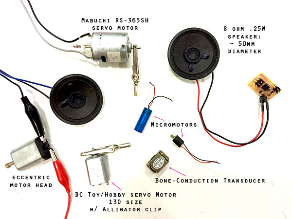
I'm trying a variety of ways to generate vibration for the pillow alarm: piezoelectric sensor, micromotors, servos with eccentric heads, and a small transducer.
Using Arduino code to send a continuous A3 note, which is 220 Hz. Here's a nice video of what different frequencies sound like, and the Arduino code I've been using to test all the vibrating things.
VIDEOS AND IMAGES, vibrating things:
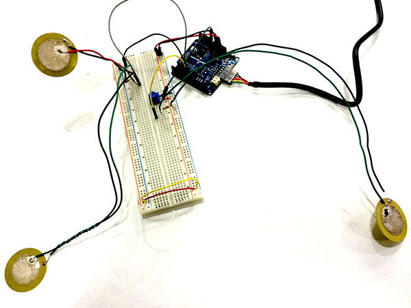
Piezos:
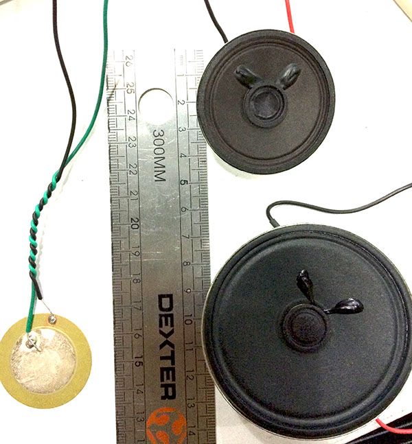
Speakers:
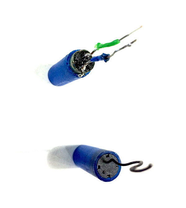
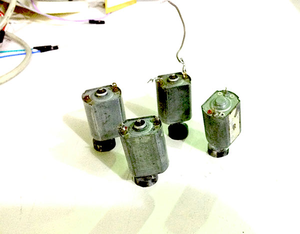
Micromotors:
Eccentric-headed motor:
Transducer:
Comparing Motors
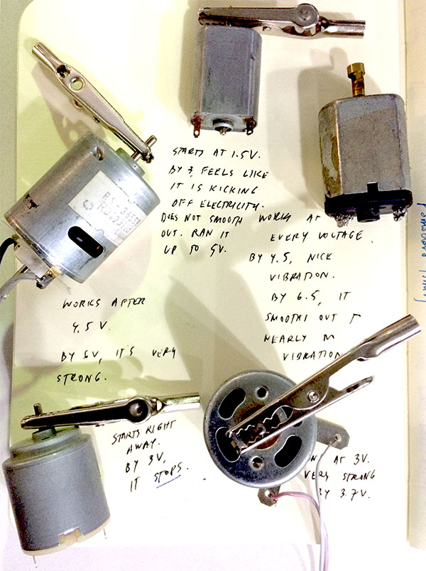
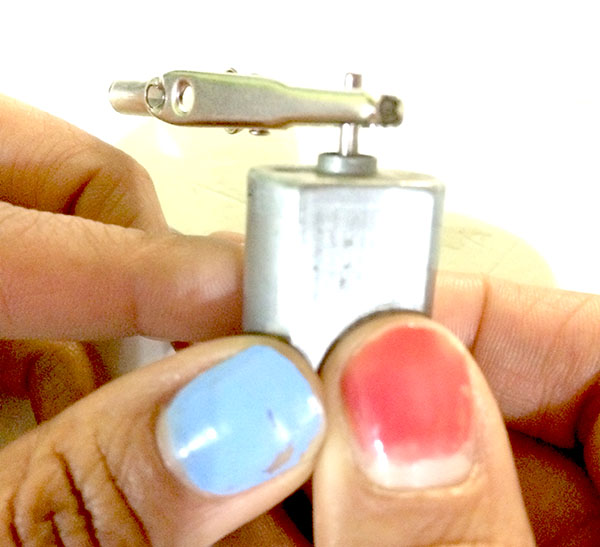
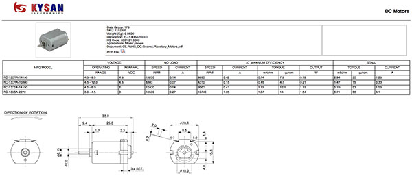
I'm choosing one that is plentiful in our lab stock. It also is nice and juddery at many voltages. Here are the specs. ~ Made in Shenzhen!
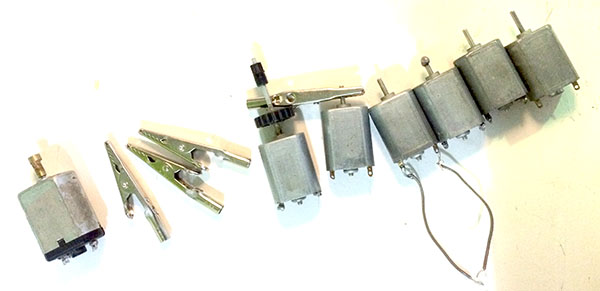
I need to add a weighted head to create vibration. Eccentric motor heads cut from 12mm steel rod and drilled:

Figuring out power
To measure amps on the motor, we added a crocodile clamp to simulate load / torque, connected one side to voltage regulator positive, the other side was touched by the red side of the multimeter, which was in the 10A hole (we would have been over in the other hole, which has a limit of 400mA). The negatives of the multimeter and the voltage regulator were connected. I ran the circuit at what I would expect from the LiPo pack, which is 3.7V. The reading was about .05A, or 500mA, for one FF-130SH motor loaded with crocodile clip.
SO, WHAT CAN I EXPECT FROM THIS Li-Po BATTERY?
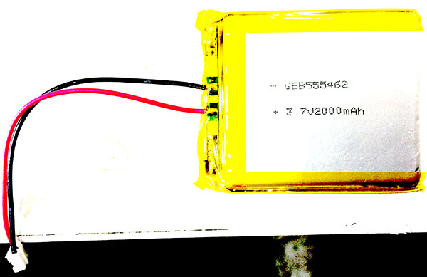
How much run-time can this 3.7V 2000mAh LiPo provide?
* The FF-130SH-14230 motor operating at 3.7V uses .05A. *
4 motors = 10hrs
5 motors = 8hrs
6 motors = 6h40min
HOW IS THAT CALCULATED?
The LiPo pack at 3.7V runs for 2000mAh ~ this is "milliamp hours." So running a motor that takes .05A is the same as saying 50 mA, so 2000/50 = 40 hours. Since I am planning to run 5 motors, I calculate 40/5 = 8. Eight hours of power for the seat, which is what I was hoping for, since that is a workday.
If I calculated for 4 motors instead of 5, it is 10 hours. My optimal range between recharges is between 8 and 10 hours. I think 10 is better, since a typical workday is often longer than 8 hours.
However, the motors will not be powered for most of the day's use. They will vibrate every five minutes prior to the "get up!" 5-min.
// REVISION, 20160613.
~ I am switching to 9V power. Once in their cases, the motors need more voltage to be felt.
Using a Camelion 9V alkaline battery. Data sheet.
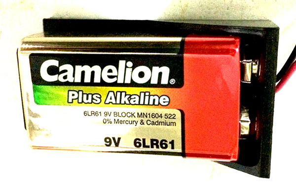
It runs 700mAh.
One motor draws 80mA of current. 240mA total.
This means one battery can run 8.75 hrs. 525 minutes. Maybe. Batteries are complicated. Best way to know how they actually are working in the circuit is to run it till there is no power.
If we are using 5 motors, the system can run 105 minutes. This is 21 5-min cycles. If we cut that in half ... it is 10 cycles.
Every 2 hrs, 4 cycles of 5-min. One day is 8 cycles. So, the battery will need to be changed daily!
I could design this so that the batteries are very easy to change ...
I am going with 3 motors, 3 batteries, and voltage regulator to supply the board. ~ I also eventually added H-bridges to this circuit. More on the board design and the circuit it controls in Week 21.
Wiring for vibration devices
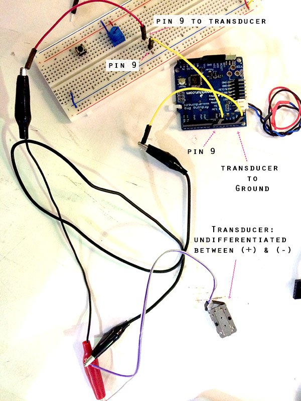
First transducer hook-up: no mosfet:
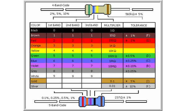
Reference on meaning of colors on resistors:
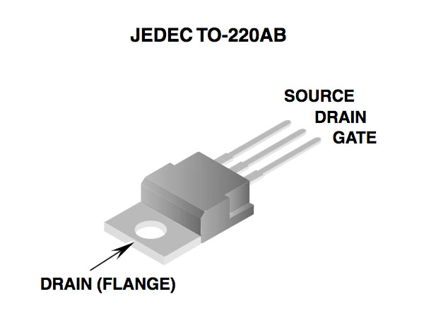
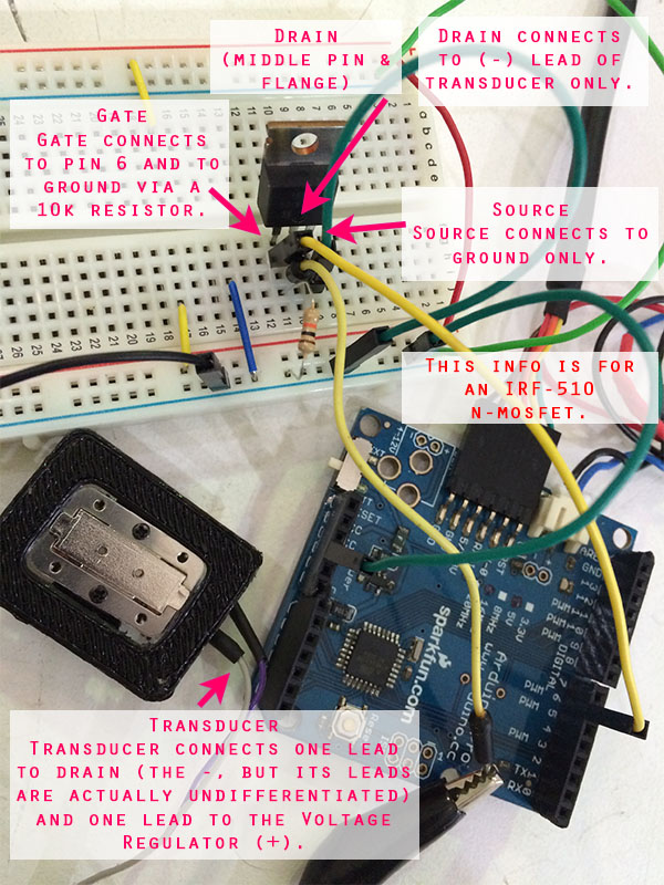
Datasheet for the IRF-510 N-mosfet, and reference pics:
Why use a mosfet? A mosfet is necessary when using above 5V with an Arduino. It allows a higher voltage to run on the circuit.
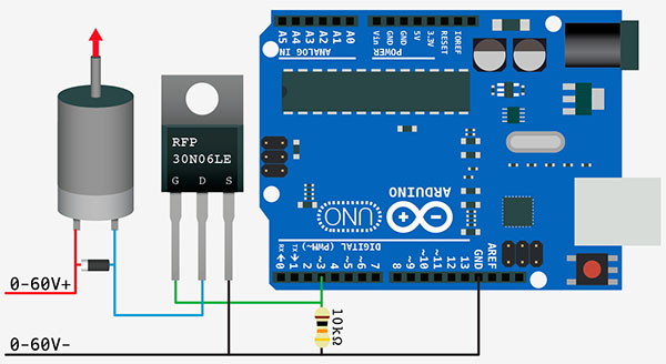
How to use a mosfet? See the following diagram drawn by Guillem, then its translation into real space.
Notes on the following drawing:
- You can see how to connect an Arduino pin to connect a mosfet and voltage regulator, along with a component.
- You can also see how to use the voltage regulator / external power to power the Arduino so that, after it is programmed, it does not need to be connected to the computer. (That's the information on the left. It is missing a diode / diodes as a safety to protect the computer / USB.)
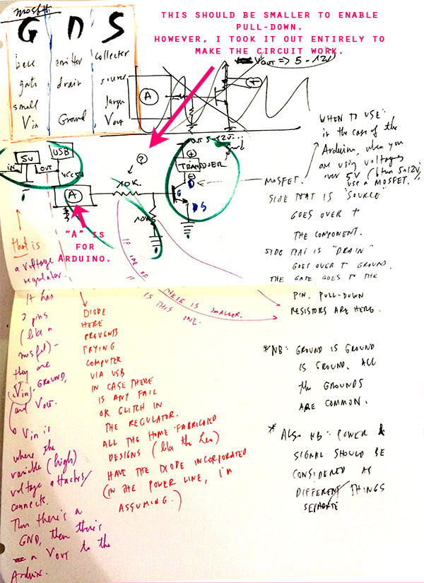
Also N.B: All components share a common ground: plug the voltage regulator and Arduino into the breadboard’s ground.
The reason why this component needed to be connected to a pin in order to test its performance at different voltages is because it is a transducer. It needs to be sent a frequency in order to perform. I sent a continuous frequency. See the Arduino program file above (with its pitches library).
Wiring for pillow interface
First, the ADAFRUIT TUTORIAL that makes it all make sense. Now, my nonsense:
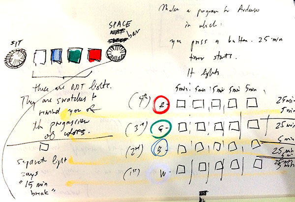
Controlling an RGB LED will help the user visualize the timing.
The pattern is based on the Pomodoro timing system:
Showing an RGB LED set-up, which is important to the user interface.
These photos help explain the components to wire:
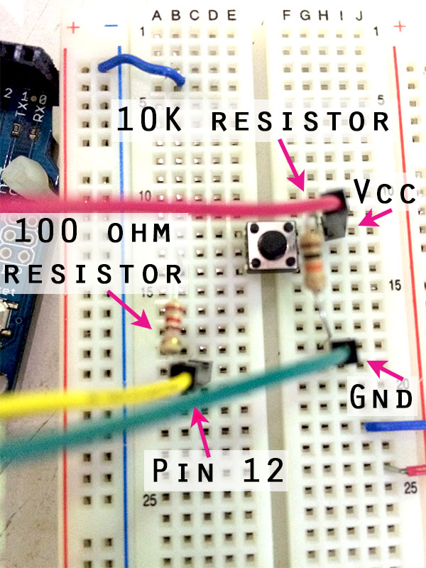
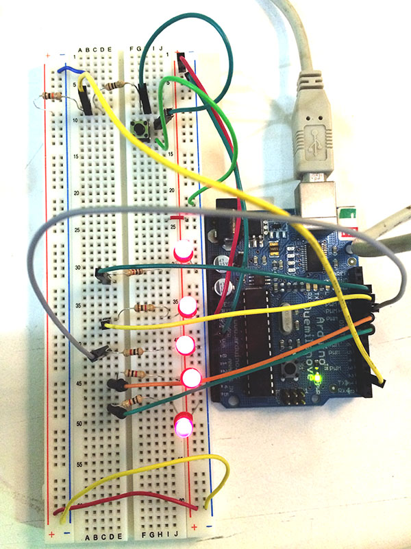
See the code for 5 LEDs and a button:
Object-Oriented Programming (OOP) to construct timing codes
This is a way to avoid the processor pause involved in the Arduino "delay" command.
Here's a great practical tutorial.
See, too, this Arduino forum for explanations of integers, unsigned integers, constants, longs, and unsigned longs ~ all things with which to be familiar in order to use OOP for an Arduino-based alarm.
Arduino has a way to use StateMachine to check how many millis since the program started running. See the explanation.
This is different from delay because it is based on a timing taken from the crystal, I am assuming. See the code in this file:
It is serial printing a time statement using an "unsigned long" which prevents a rollover into negative numbers when the limit of the number range is hit ...
I'm not sure what happens when the limit is reached.
Tiny44 is an 8-bit controller. This means it can hold: a mere 255 numbers! Hmm ...
If I understand better, the "unsigned long" code makes it possible to store 2^32. Can't say I understand how on a 2^8 system.
See Arduino's reference on the unsigned long.
And the reference on "L," long integer, which says:
"Long variables are extended size variables for number storage, and store 32 bits (4 bytes), from -2,147,483,648 to 2,147,483,647."
Okay, however this magic works, I take it. It means I can have about 2.15 billion numbers stored.
See video: learning to do simultaneous timings with StateMachine code:
Code for this video:
I also made a code for 3 State Machines. The following link is the code for 3 LEDs blinking on separate rhythms (no button). As I said earlier, using "state machines" allows this to happen without the pause caused by the "delay" command.
Remaking a Board; Electronics
(Re)Making a Board
I created a low-memory Arduino from the Hello World Board.
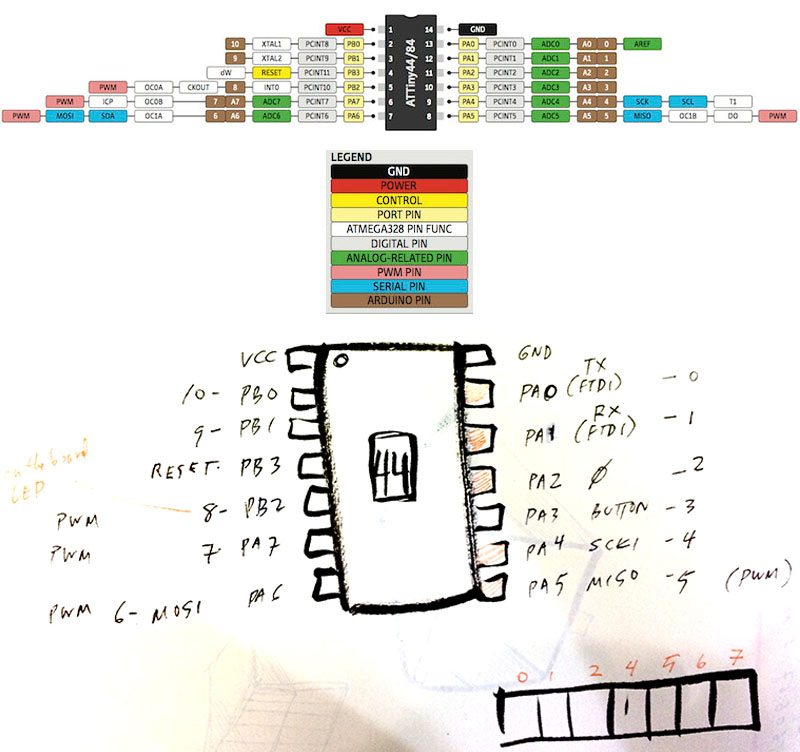
Seven new pins, all working:
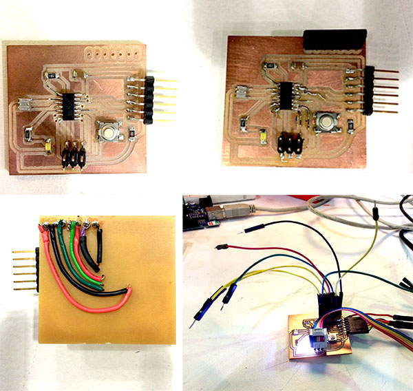
Electronics
I am going to have a problem with the sparse pins and memory on my AtTiny 44 and driving 4 RGB LEDs. However, Donato gave me a 4-string set of Neopixels! What a gift. Each Neopixel contains its own driver, so you can control each "pixel" with its own color and timing, and take up only one pin on an Arduino. If you use a standard surface-mount RGB, such as we have in the Fab inventory, you will need 3 pins per LED, because you need to call a PWM for each color separately.
- About Neopixels:
- the product from Adafruit
- some info about how to use for beginners
- the way to make the same thing without the product: dealing with WS2812B
Extra: A reference video on color.