Week.09 Mechanical Design
Photoclock
We agreed on realizing a very simple clock with a digital camera inside that gets a picture every day of the class in Fab Academy, from Monday to Friday at 3.00 pm.
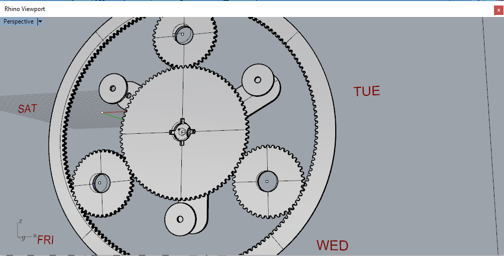
We decided to start with a planetary gear system being the base for the mechanical part and input of the camera.
3D Model
Elia designed the model of the machines, using the gear calculated by gear generator.
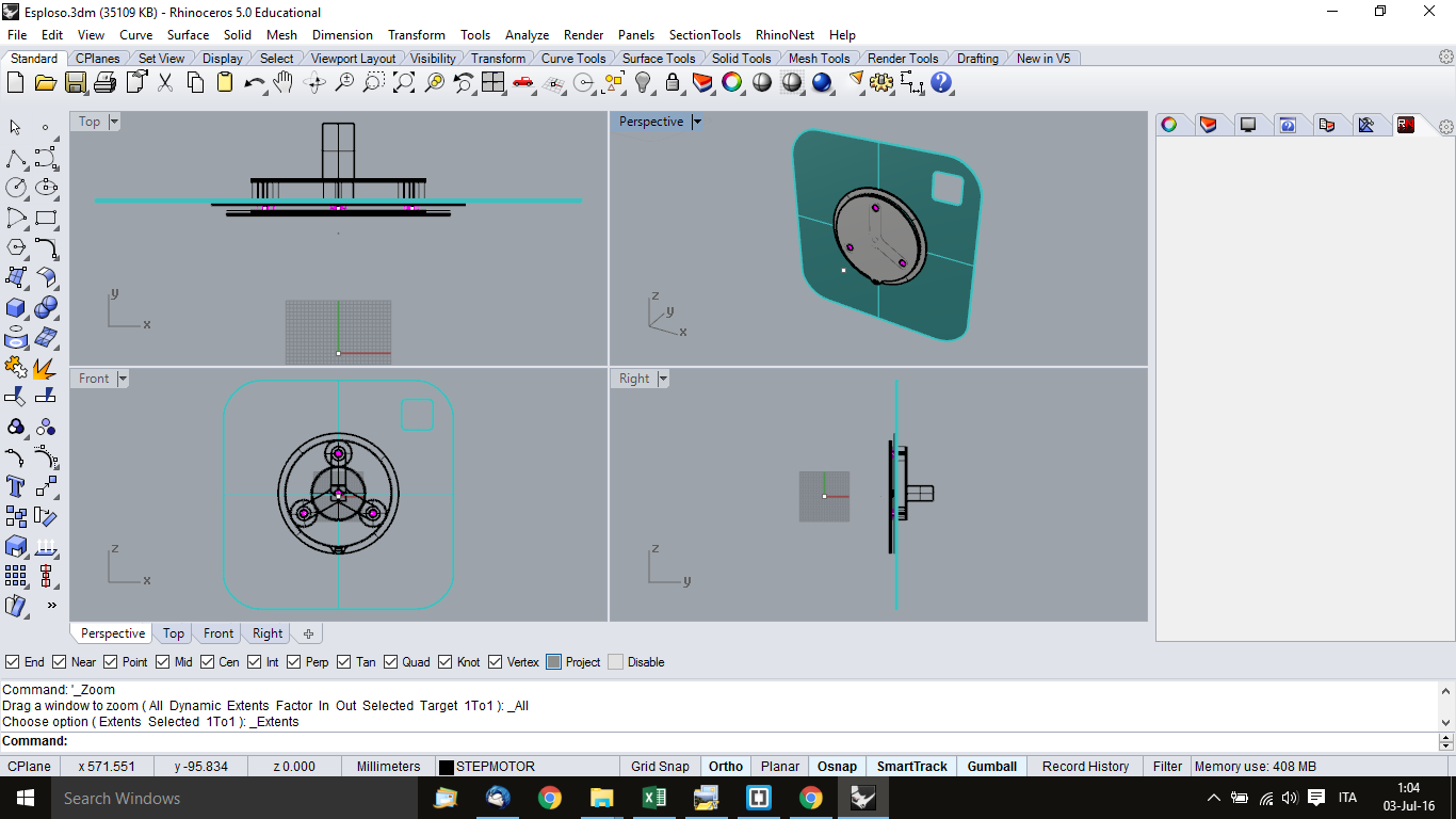 3D model of Photoclock Machine
Source 3D Model full model with all mechanical parts
Photoclock.3dm
Gear Generator
Elia designed the model of Photoclock using Rhinoceros, calucalted the gear and looked for some software to generate gears.
Donato found many gear applications, but all of them had the limit of generating a maximum of 200 teeth.
We tested also GearGenerator3.Patched.exe, but the teeth amount problem remained.
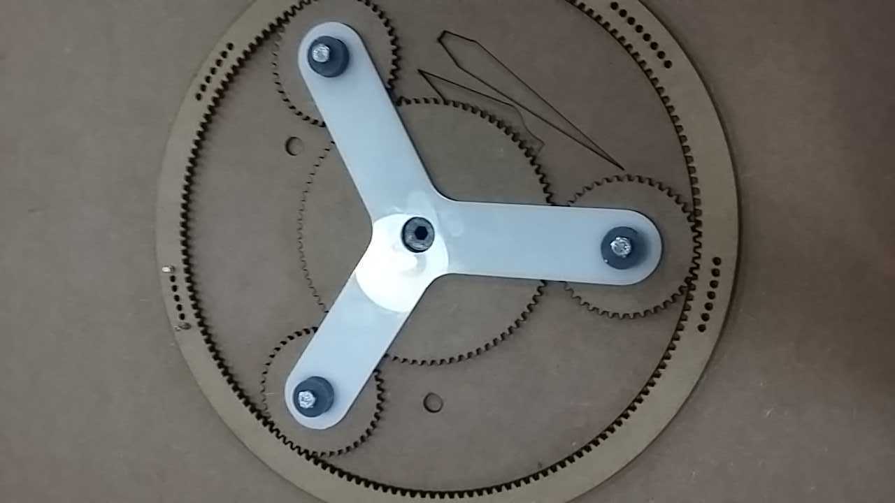
Teeth
External 168 teeth
Central 84 teeth
Small 42 teeth
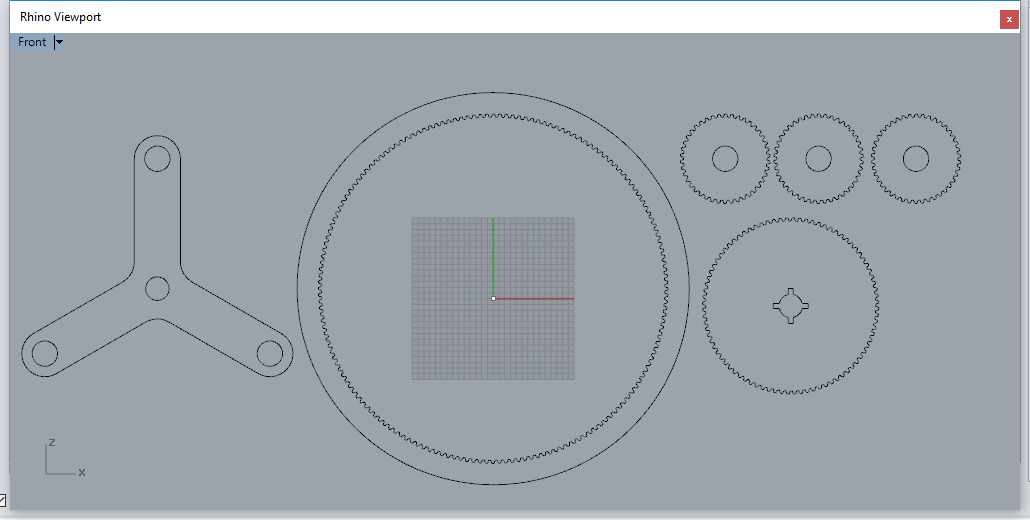
The External gear has 168 teeth, which is the amount of hours in a week. The Central gear has 84 teeth, the three small ones have 42 teeth each.
Source Software
Gear Generator web page
GearGenerator3.Patched.exe
Source 2D file.dxf
Planetary Gear.dxf
Step motor locking
Donato designed the Step motor locking. The step motor screw has not to be longer than the thickness of the wood. We replicated the triangular shape of the planetary rotating it by 60° so that it does not interfere with the movement of the gear.
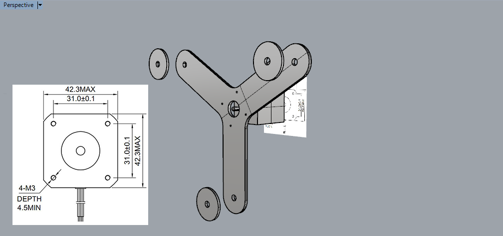
 We placed the Step motor locking into the planetay system.
Source 2D file.dxf
Step motor locking.dxf
Mechanical Production
Donato Polignone has laser cutted the gear.
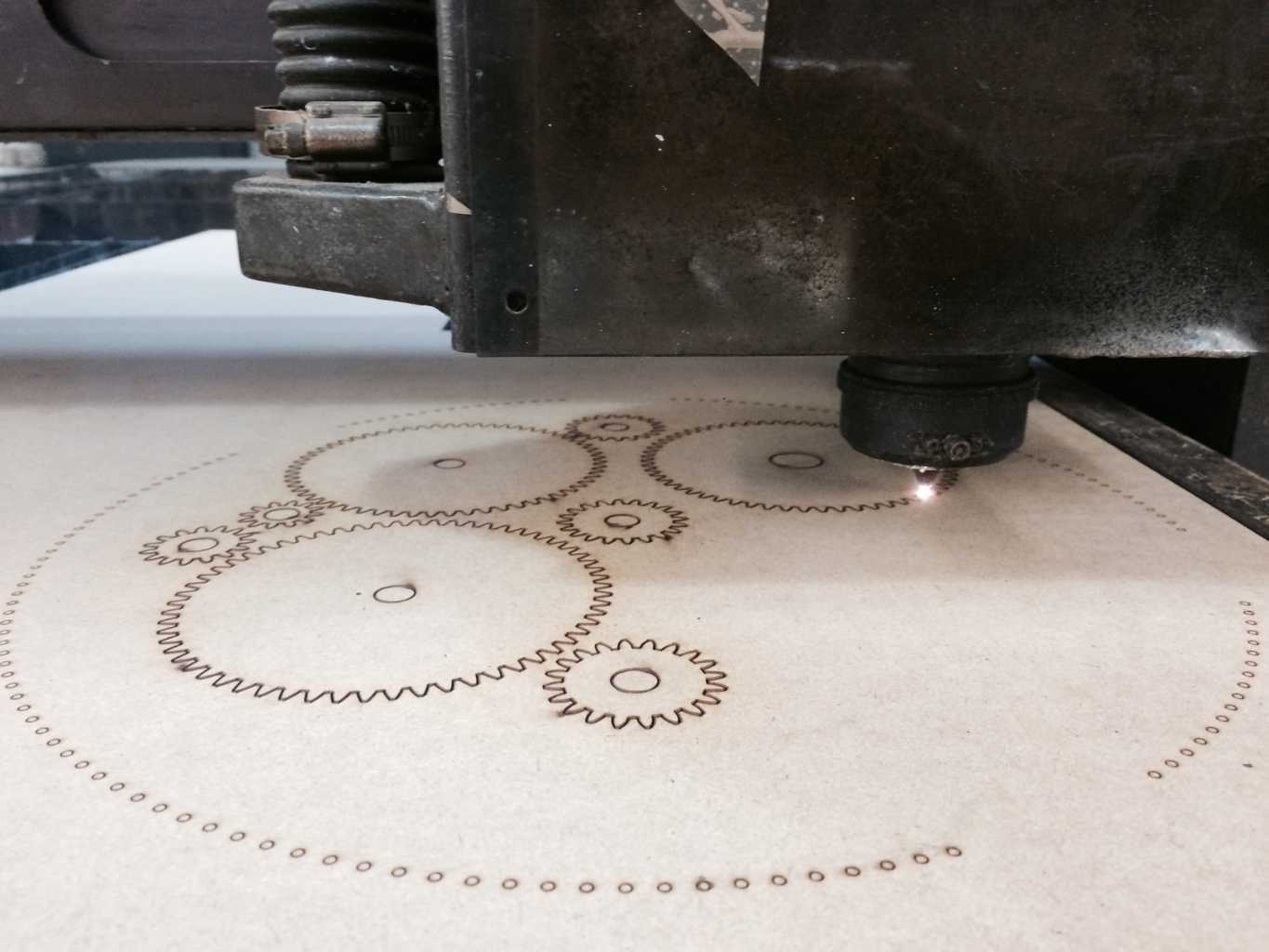
Laser cutter
Speed 10%
Power 360
Elia has 3D Printed the plastic bearing

3D Print Parameters
layer height 0.2
shell thickness 0.8
bottom/top thickness 0.8
fill density 35
print speed 60
support type: none
platform adhesion type: raft
Source 3D Print
3D Print plastic bearings.stl
The Trigger
Elia designed and placed an end stop with a wheel as a switch in correspondence of the bigger external crown. A sequence of screws, placed in the correspondent hole created a relief that actuated the switch. Screws allow also to regulate and fix the height.
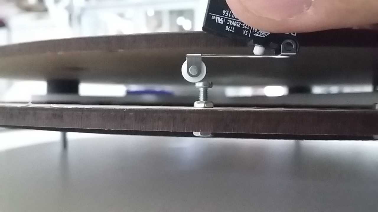
The switch created it will be connected to the Arducam pin and it will works as trigger for get the picture into the camera.
Assembly and move handly
Copyright © Elia De Tomasi 2016