Computer-Controlled Machining
Task: | 'Make something big'
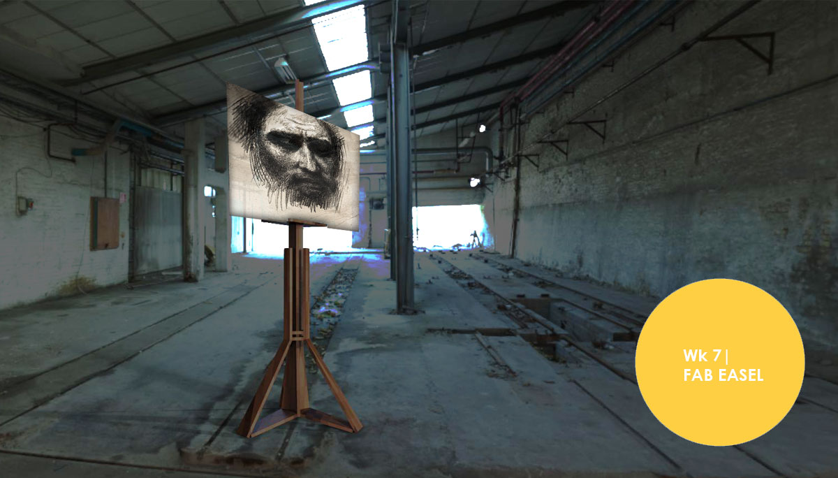
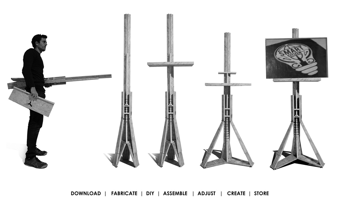
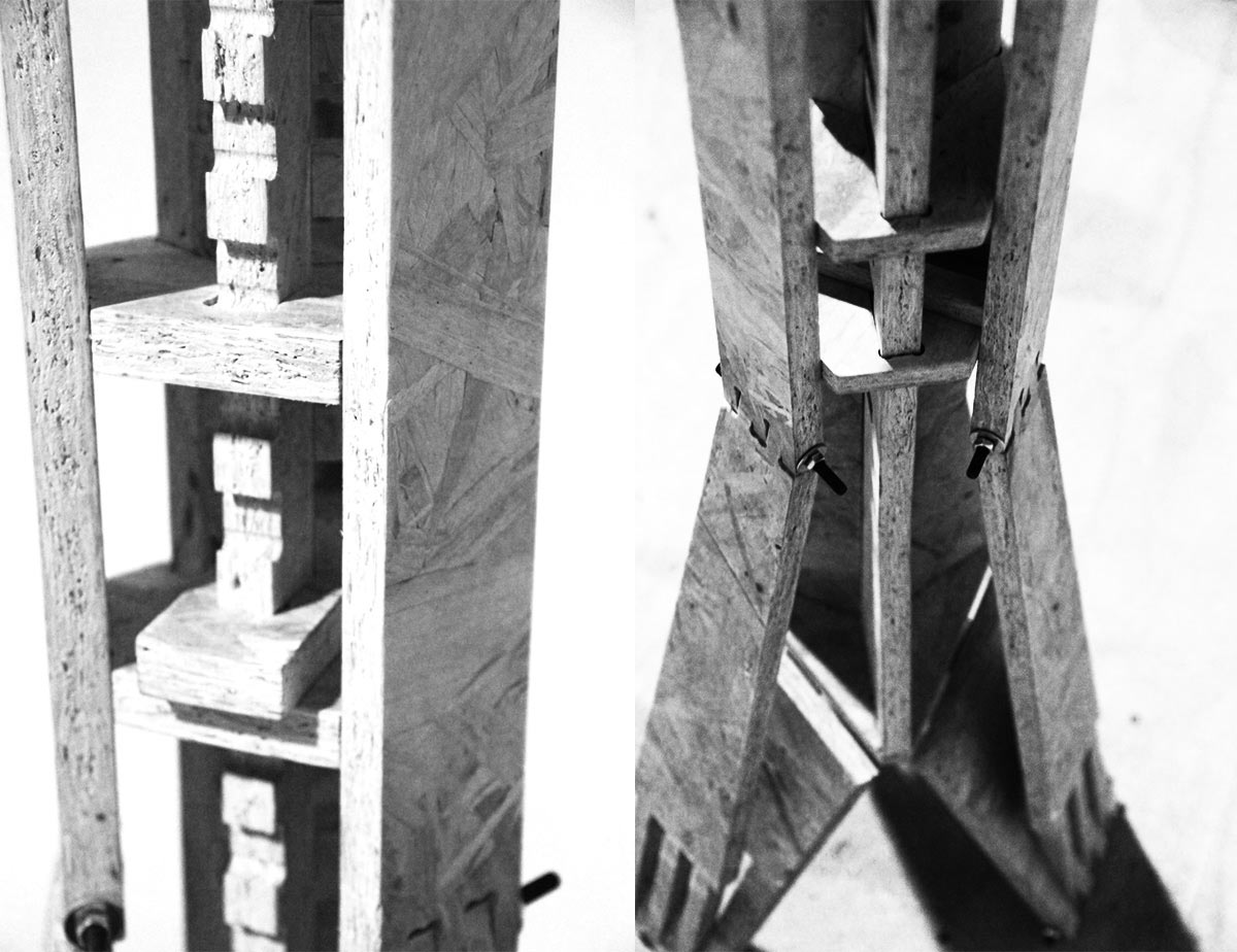
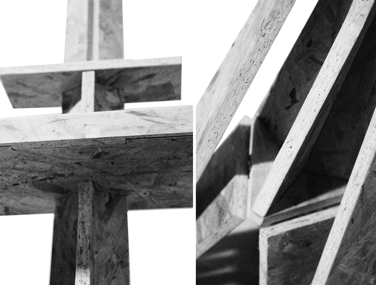
The objective this week was to design and fabricate a 2d object in 3d using one piece of chipboard; with a flat end mill. I took this as an opportunity to focus wood joints (rotation; corner; stoppers) and to develop an easy DIY; open-source fab lab product from scratch. Thus the design of an easel.
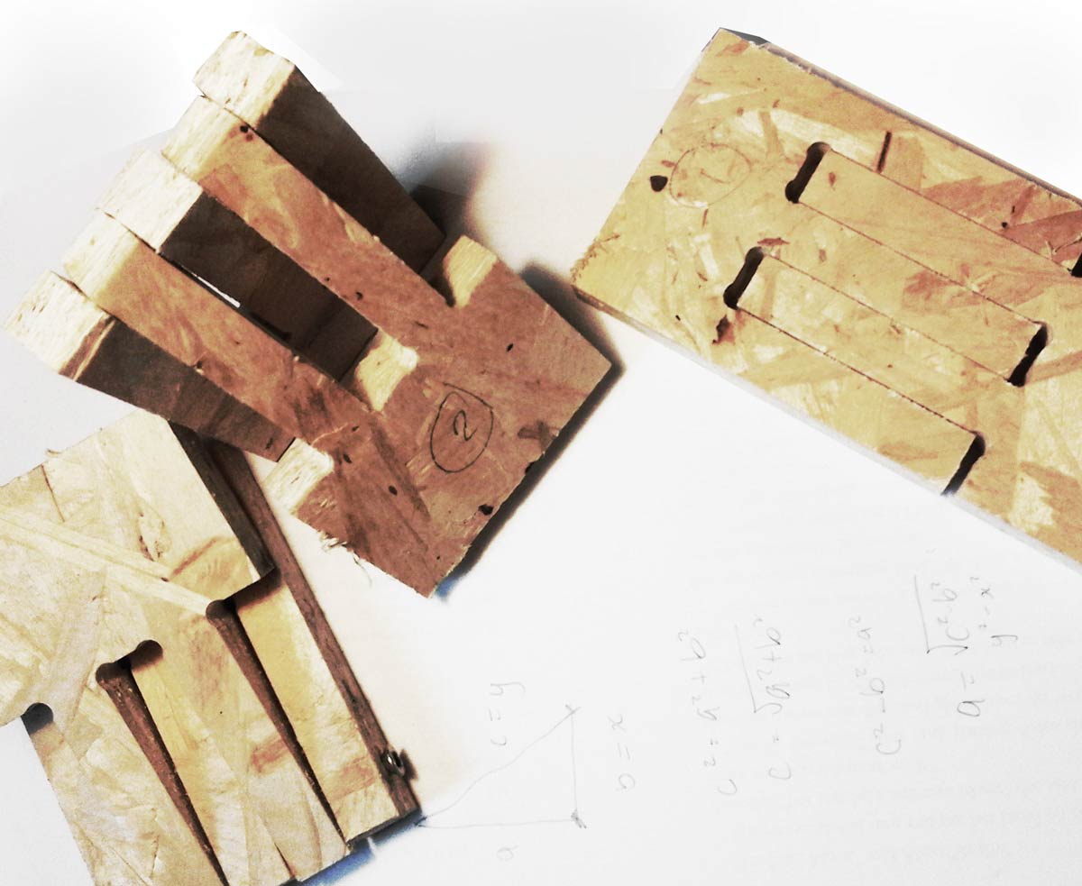
The design was logically processed using grasshopper3d (rhino3d plug-in); the key factor was the use of pythagoras therom functions as wood lenghts would need to be constant and z-movement; a variable. This resulted as a system which would work as a deployable structure and a variable tensegritry structure.
To fabricate and design joints some tests were made to understand which kind of joints and gaps could be used in different places and depend; as little as possible; on other materials. This test used a gap of 0.1mm; 0.2mm; 0.3mm; on both sides. As a result 0.1mm was used for fixed joints and .3mm for flexible joints in the final cut.
|Partworks|
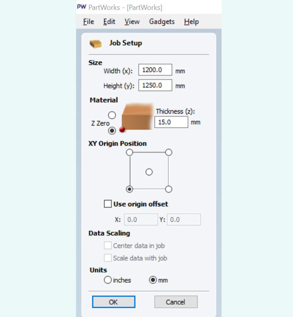
Once you have the interface open and file imported as a dxf. Join all lines as vectors in partworks ( tool "joint open vector" under "edit vectors". Choose stock and a strategy in 2d:-
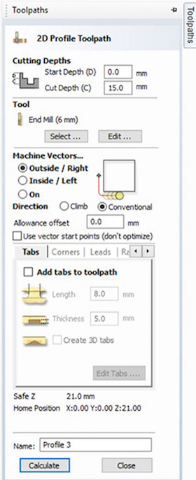
1. Choose your strategy. First; "Profiling" for cutting through. The diameter for a flat end mill was chosen to be 6mm. We can make three different types of Profile toolpaths and these are: Outside the line, inside the line, or on top of the line. To change or set toolpath definitions, in the next window, go to "edit" for the tool this project has definitions for two toolheads. Cut depth for profiling this material was set to 15mm; spindle speed for this wood 12000rpm; feed rate 60mm/s and pluge rate 20mm/s
 2. Strategy "Pocketing" for cutting say halve way- to create tidy details diameter of mill here is also 6mm
3. drilling/ hole for drill.; holes for creating drill (3mm to drill).
Bottom of stock placed from origin in rhino and bed is oriented according to xy axis of machine. Set thinckness of material.
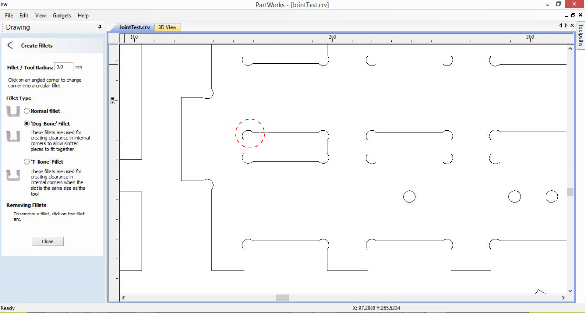
Be sure to create dog bones to for corners in cnc (can be done with attached grasshopper definition or directly in partworks)
Generate the Drill Path. Under "Toolpath Operations" choose "Create Drilling toolpath" change "Tool" Select the circles and Calculate in partworks
The same process applies for pockets and Cut choosing it's Operation accordingly. In the case of Pockets you have to choose the depth you want your pocket to have.
As for cutting there are more options, Choose if the machine cuts in the inside or outside of the vector and a great feature is adding Tabs to secure your pieces to the board.
Save Toolpaths: The order you save it is the order in which the machine will cut, this is very important. In the case of the Drills it must be saved in a separate G-code because you are going to use a Drill bit.
|Rhinocam|
Rhinocam also works with strategies. Once you have your model in rhino; create outlines for strategies. e.g zones for pocketing and profiling. Later on in composites you will see how to create finishes on a surface in 3d
The softer your material the less feed rate you will need. Always rememeber to leave a step over distance of say 4 and a tolerance according to how accurate you want your finish. Tabs can be done manually or automatically from 'regions' and then uploaded in 'drive regions' for profiling. in strategic locations not to allow pieces to come off during production. Just make sure that you create tabs in a way that drill does not effect path.
When selecting the boundary make sure to clear all drive regions first and manually select curves from file in rhinocam. Make sure the machine cuts outside/in (outside first). For this cut; "conventional method"; is prefered and so is "push out" for the mill placing less stress; but also less quality.
for more info on Rhinocam |press|
|Shopbot|
A post processor was used for rhinocam to shopbot which was done by other IaaC users; The code converts rhinocam code to shopbot code as found in these Command references . Unfortantely this was giving us a lot of trouble and thus had to resort to Part works- which was much more straight forward in generating gcode.(once simply selects strategies for different parts- profiling/ pocketing...)
Note. Incase the processes automatically stops in the middle of the process take note of gcode numer. Then edit the gcode untill that line and send again; making sure that zero axis was kept.

|Machine set up
1. Save file in folder on computer of cnc
2. Open shop-bot interface
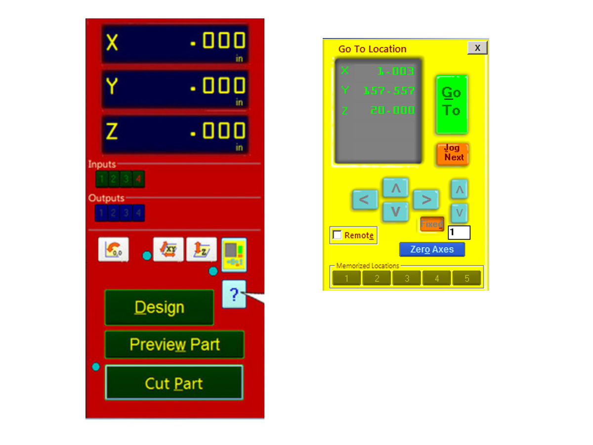
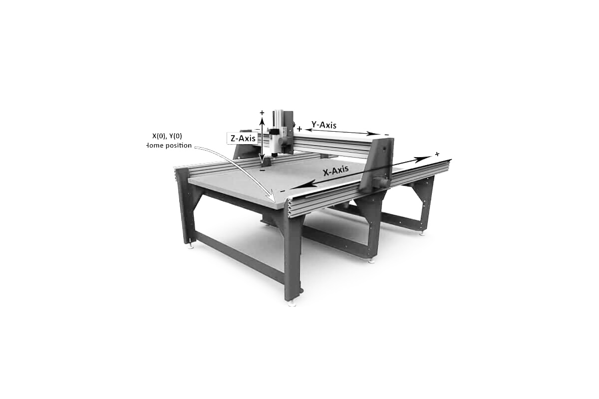
3. Press "k" to open the keypad movement; moving keyboard key you can move x,y(x is the larger side); page up and page down for z movement. The '0,0 button' will send the machine to its generic home position
4. Change the bit using router tools and button.
5. Place the material leaving a bit of space on the side to 0 axis.
6. Place the sensor to bottom of bed if using bed as stock zero point(make sure you understand x and y in rhino3d).
7. Move to 0 point and enter zero for all axis as new home.
8. load profile to make holes or in the case of say foam clamp down before step 6.
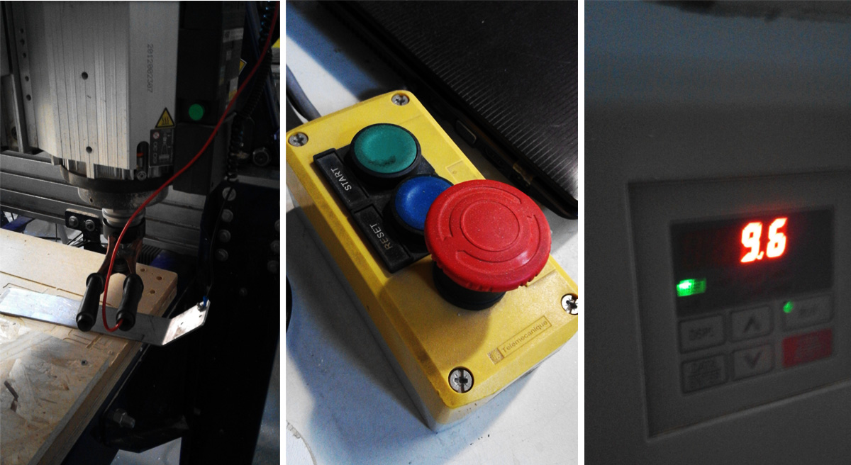
9. Press green start button (not use red button only incase of emergency otherwise pause from interface) You can chage the revs from the machine should you need to go faster or slower.
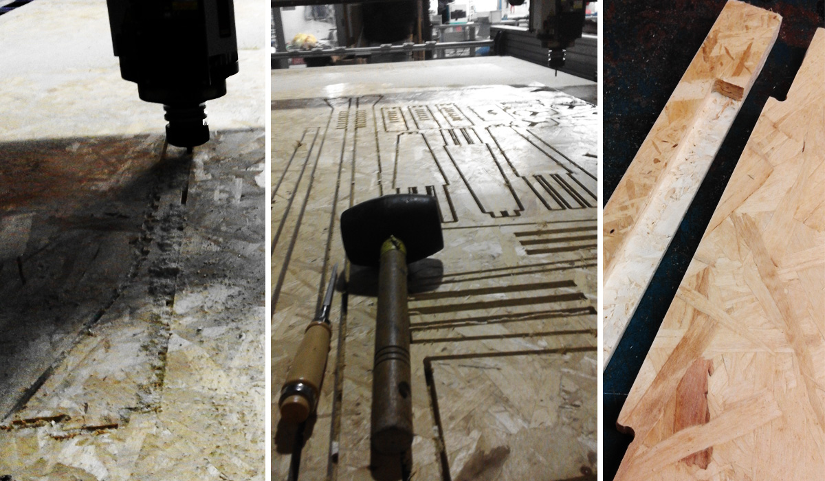
Once process is over remove tabs manually using a soft hammer and chisle. Sand properly and press fit the joints. In the case of the legs; a pillar drill was used carefully to make holes of 4mm and 6 shoulder screws to allow pivoting.
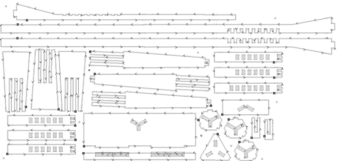
These were the results:

|Download this weeks files .
|Brief MIT
|Lecture Neil Gershelfeld