wk8: 2016/03/16
EMBEDDED PROGRAMING (WEEK 2 OF 2)
0. Assignments for wk8
The assignments for wk8 were as below;
- Read a microcontroller data sheet
- Program your board to do something, with as many different programming languages and programming environments as possible
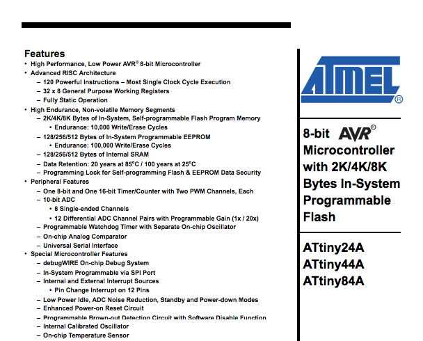
1. Reading a microcontroller data sheet
This week, Prof. Niel directed us to read Datasheet: Microcontroller ATtiny44A to deepen the understanding on electrical production and embeded programming. I tried to understand the overview and major abbreviations on it since it had too many pages to read, 286pages of PDF!.
Datasheet: Microcontroller ATtiny44A
Overview
The one of most important information on datasheet is pin configurations, which shows below.
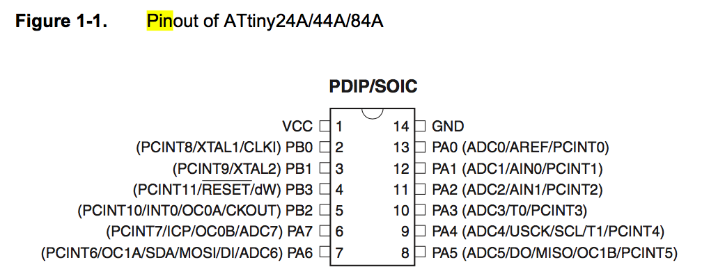
PIN configurations of ATtiny44A
To understand how I can handle the microcontroller and what its function is, I quickly summarize the definition of Abbreviation as below.
| Abbreviation | explanation |
|---|---|
VCC |
Supply voltage. |
GND |
Ground |
RESET |
Reset input. A low level on this pin for longer than the minimum pulse length will generate a reset. |
Port A |
a 8-bit bi-directional I/O port with internal pull-up resistors (selected for each bit). |
Port B |
a 4-bit bi-directional I/O port with internal pull-up resistors (selected for each bit) |
ADC |
Analog to Digital Converter |
AREF |
External Analog Reference for ADC. |
PCINT |
Pin Change Interrupt source |
AIN |
Analog Comparator Positive Input. |
T |
Timer/Counter, counter source |
USCK |
Three-wire mode Universal Serial Interface Clock. |
SCL |
Two-wire mode Serial Clock for USI Two-wire mode. |
DO |
Data Output in USI Three-wire mode. |
MISO |
Master Data input, Slave Data output pin for SPI(Serial Peripheral Interface) channel. |
OC |
Output Compare Match output |
XTAL |
Chip Clock Oscillator |
CLKI |
Clock Input from an external clock source, |
dW |
debugWIRE |
INT |
External Interrupt Request |
CKOUT |
System Clock Output |
ICP |
Input Capture Pin |
SDA |
Two-wire mode Serial Interface Data. |
MOSI |
Master Data output, Slave Data input for SPI channel. |
DI |
Data Input in USI Three-wire mode. |
2. Preparation for programming
Setting programming environments
Before starting programming, I had to prepare the environments of embeded programming. I had alredy installed Arduino IDE, so I installed FTDI driver, and added Attiny to Arduino IDE.
Arduino
is common term for a software company, project, and user community that designs and manufactures computer open-source hardware, open-source software, and microcontroller-based kits for building digital devices and interactive objects that can sense and control physical devices.
IDE
is abbreviation of Integrated Development Environment, which is a software application that provides comprehensive facilities to computer programmers for software development. An IDE normally consists of a source code editor, build automation tools and a debugger.
FTDI
is abbreviation of Future Technology Devices International, which is a Scottish privately held semiconductor device company, specializing in Universal Serial Bus (USB) technology.
Checking the connection between the programmer and the board
Next, we have to check the conection between the programmer, this case USBtiny, and the board, this case "hello echo board". We can initialize the USBtiny, using the Linux commnad:
avrdude -c usbtiny -p t44
If the message is shown as below, you initialize the AVR device successfully and the connection is right. So now I finished preparation to write any programs to the board.
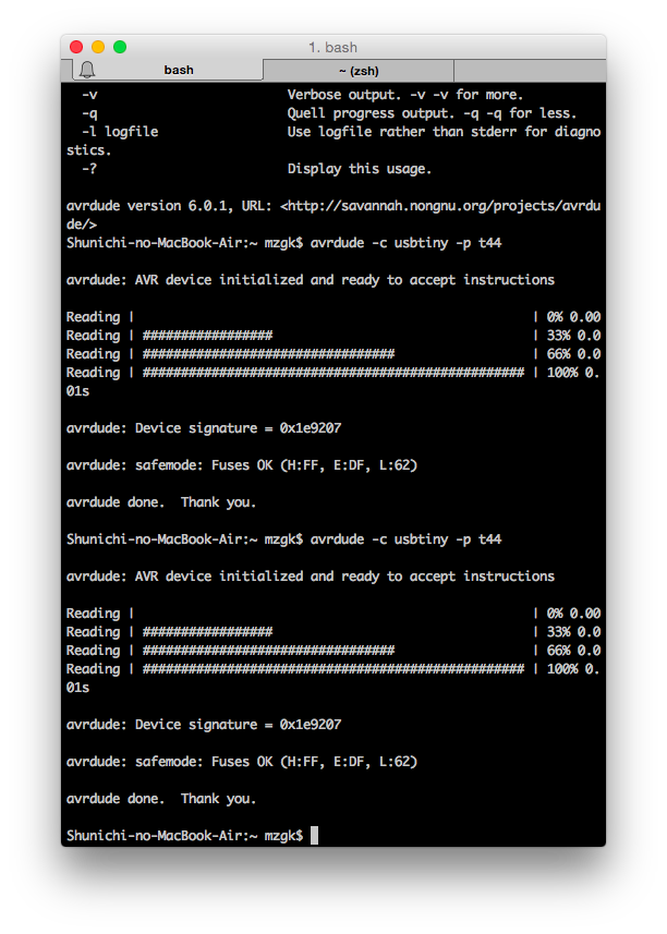
Initializing the usbtiny
Of course, you have to change the part of the commmand, especially t44, which is the part indicating the microcontroller, ATtiny44. You can refer the commands for otehr microcontrollers from this AVR Tutorial page.
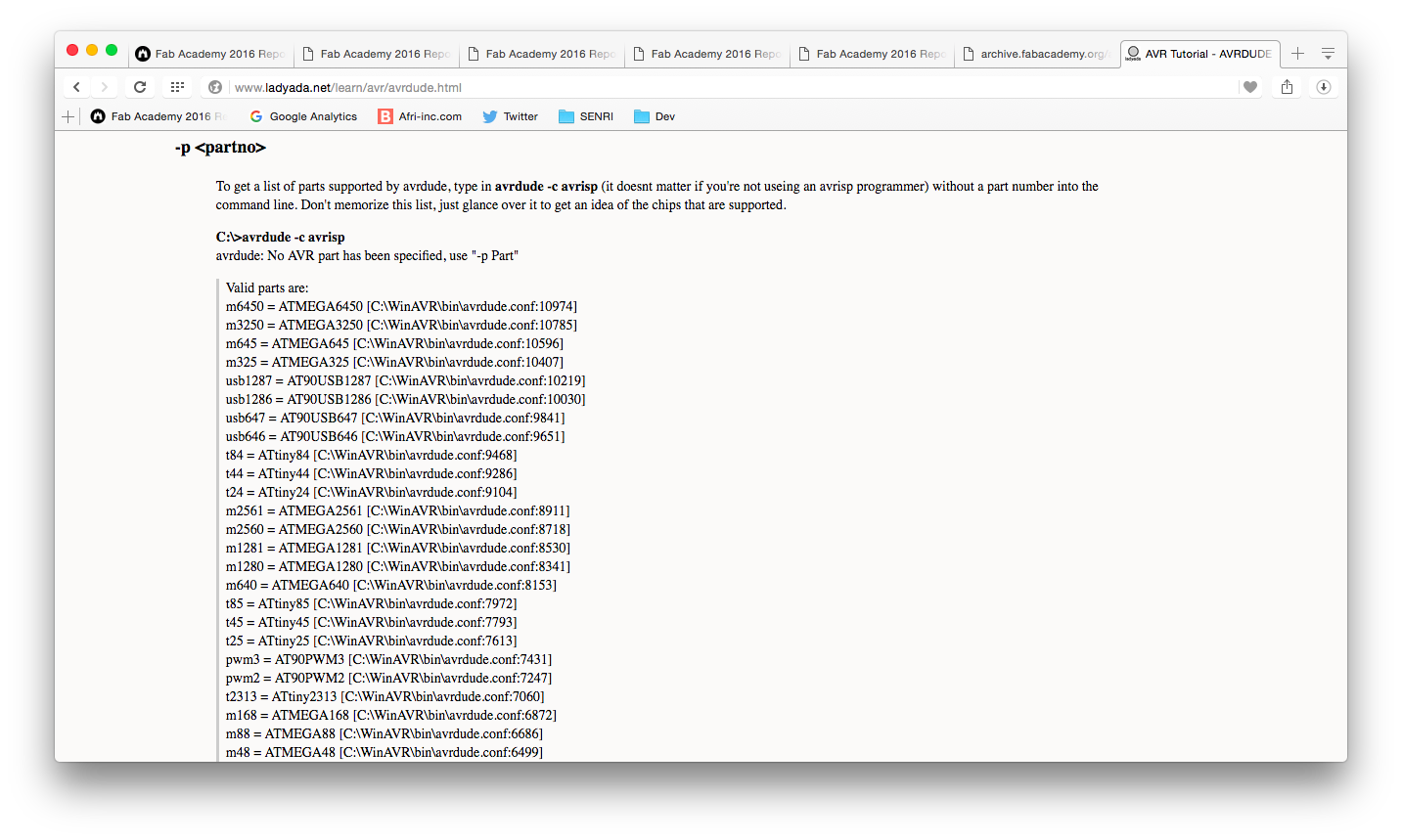
Command list of each microcontrollers
Burning bootloader
We also had to run the "Burn Bootlooder", following Add the Attiny to your board list in Arduino IDE. To understand the Bootloader development, the website below was very useful.
Boot looder
also called a boot manager, is a small program that places the operating system (OS) of a computer into memory. When a computer is powered-up or restarted, the basic input/output system (BIOS) performs some initial tests, and then transfers control to the master boot record (MBR) where the boot loader resides.
For burning bootloder, the exact setting is as below;
This setting is really important if you use wrong setting, it will not work.
- Board: "ATtiny"
- Processor: "ATtiny44"
- Clock: "20MHz (external)"
- Programmer: "USBtinyISP"
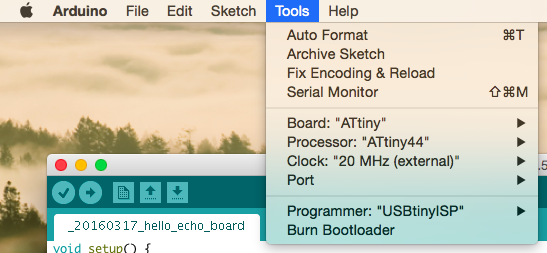
Setting for burning bootlooder
Then, I run the bootloader on Arduino, and succeeded to run it as the screenshot below. According to Emma, our electrical instructor, we can run bootloader only once without mistakes, so I was seriously relieved when I can check the result.
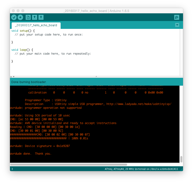
Burning Bootlooder
Learning C language
Also, pure C is main programming language of Arduino, I quickly learned how to write C language using Dot Install: C Basic course, which is Japanese freemium programming learning support site because this is first time for me to write C though I used Ruby on my programming work.

Dot Install (for Japanese only)
Here I add the list of major codes on Arduino below;
| C Code | explanation |
|---|---|
int |
Show the working tree status |
byte |
Show the working tree status |
print |
Show the working tree status |
serial |
Show the working tree status |
3. Enjoying Programming a board
Blinking test
First, I tried very simple blinking test, which was the simplest one from Arduino library, to see correct correspondence between pin number of Arduino and those of hello echo board.
To identify the correspondings, the web page below was very useful.
There is a table of correspondings, so that I could quickly identify it as the table below.
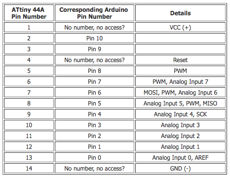
ATtiny 44A vs. Arduino Pin-Out Numbering
Then, I referred the schematic of hello-echo board, and found that the pin connected to LED was pin7 on Arduio.
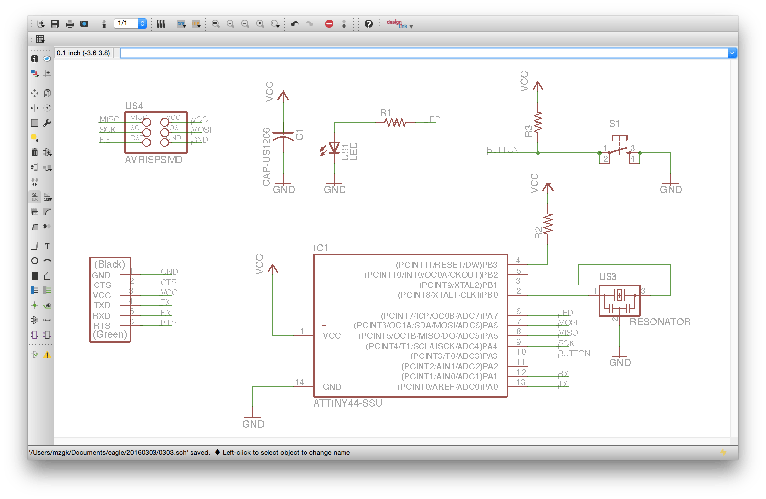
Schematic of hello-echo board
The code as below is the first test one, which is very simple blinking program.
int pin_number = 7;

void setup() {
  pinMode(pin_number, OUTPUT);
}

void loop() {
  digitalWrite(pin_number, HIGH);   // turn the LED on (HIGH is the voltage level)
  delay(1000);              // wait for a second
  digitalWrite(pin_number, LOW);    // turn the LED off by making the voltage LOW
  delay(1000);              // wait for a second
}
Next, I would like to test the attribute of PWM, then I wrote the code as below. Regarding the PWM, Arduino: PWM is very easy to udnerstand.
PWM
is abbreviation of Pulse Width Modulation, which is a technique for getting analog results with digital means. Digital control is used to create a square wave, a signal switched between on and off. This on-off pattern can simulate voltages in between full on (5 Volts) and off (0 Volts) by changing the portion of the time the signal spends on versus the time that the signal spends off. The duration of "on time" is called the pulse width. To get varying analog values, you change, or modulate, that pulse width. If you repeat this on-off pattern fast enough with an LED for example, the result is as if the signal is a steady voltage between 0 and 5v controlling the brightness of the LED.
int pin_number = 7;

void setup() {
  pinMode(pin_number, OUTPUT);
}

void loop() {
  analogWrite(pin_number, 255);   // turn the LED on (HIGH is the voltage level)
  delay(500);              // wait for a second
  analogWrite(pin_number, 200);    // turn the LED off by making the voltage LOW
  delay(500);              // wait for a second
  analogWrite(pin_number, 150);    // turn the LED off by making the voltage LOW
  delay(500);              // wait for a second
  analogWrite(pin_number, 100);    // turn the LED off by making the voltage LOW
  delay(500);              // wait for a second
  analogWrite(pin_number, 50);    // turn the LED off by making the voltage LOW
  delay(500);              // wait for a second
}
Then, you can see the result of implementation from the video below.
Blinking test
Next, I would like to try simle if sentense on Arduino, so I wrote the simple code reading the status of switch and turing light on/off accordingly.
int led_pin = 7;
int sw_pin = 3;

int sw = 1;

void setup() {
  pinMode(led_pin, OUTPUT);
  pinMode(sw_pin, INPUT);
}

void loop() {
  sw = digitalRead(sw_pin);

  if (sw == HIGH) {
    digitalWrite(led_pin, HIGH);
  }
  else {
    digitalWrite(led_pin, LOW);
  }
}
Hello World Test
Next, I tried serial connection using FTDI cable, which I bought with other menbers. Regarding the difference between serial communication and parallel communication, I learned from this page: sparkfun - Serial Communication.
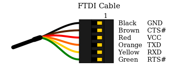
Pin configurations of FTDI cable
Serial Communication
is the process of sending data one bit at a time, sequentially, over a communication channel or computer bus. This is in contrast to parallel communication, where several bits are sent as a whole, on a link with several parallel channels.
I wrote the code below and successfully run the program in the end though at first I was struggling to try run the serial communication with FabTinyISP connected to my laptop...
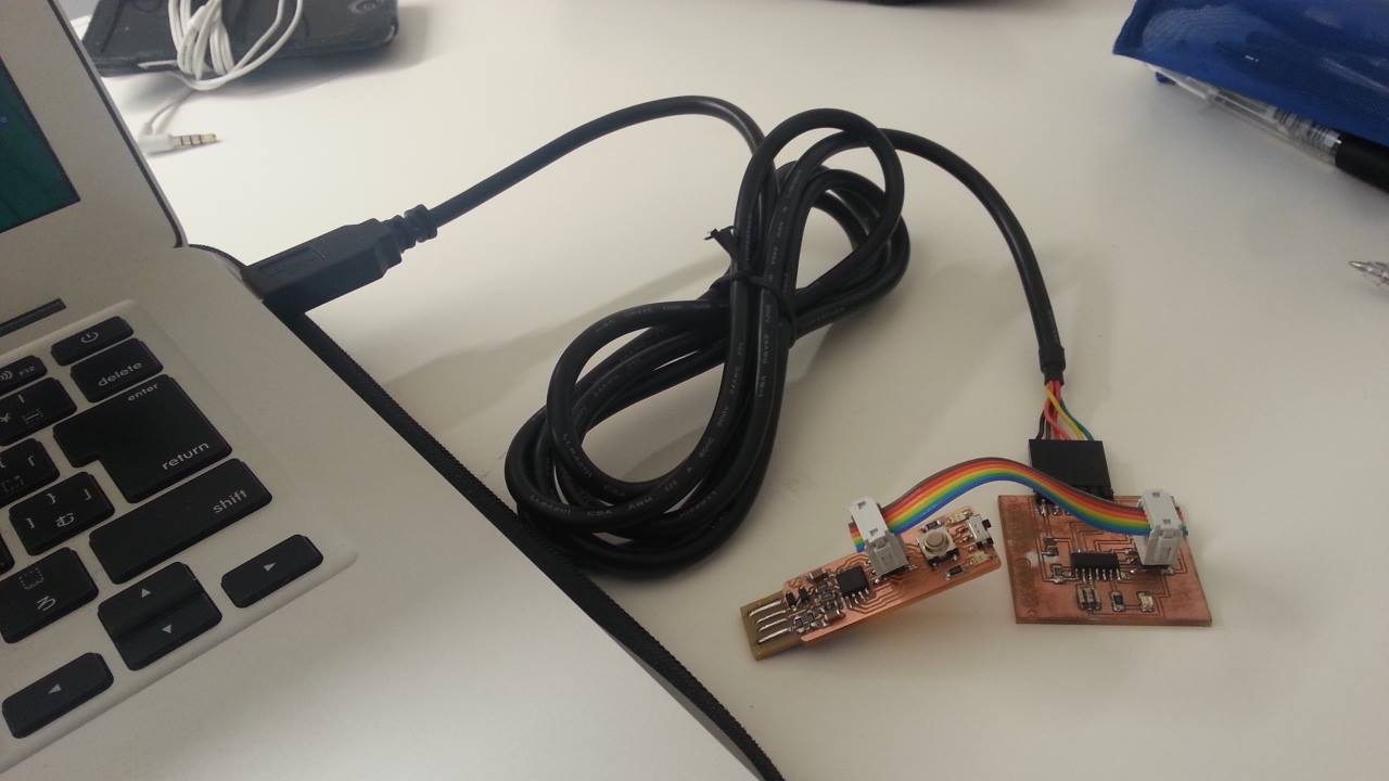
Hello-echo board connected by FTDI cable
#include#define pin_rx 0 #define pin_tx 1 SoftwareSerial serial(pin_rx, pin_tx); int sw_pin = 3; int sw_value = 0; void setup() { serial.begin(9600); pinMode(sw_pin, INPUT); } void loop() { sw_value = digitalRead(sw_pin); serial.println("hello World"); delay(1000); }
Though I would like to try the other programming languages and environments, and further complex programming, the time was up. The result of hello world programming is as the video below.
"Hello world" on serial communication
Outline of this page
1. Reading a microcontroller data sheet
2. Preparation for programming
3. Enjoying Programming a board
Download output of wk8
Here are my output files for wk8:
- 20160317_blink_test.ino
- 20160317_blink_test_v2.ino
- 20160317_blink_test_v3.ino
- 20160317_hello_world.ino
Lecture Material for wk8
Lecture Note
Tools
Learning Support
- Introduction to Make and Makefiles
- Install Arduino IDE 1.6.5
- Add the Attiny to your board list in Arduino IDE
- Install the ftdi drivers
Videos of wk8
Here you can find this weeks's lectures on VIMEO:
(2016.03.16)
(2016.03.30)
Checklist for wk8
Assignments:
- Read a microcontroller data sheet
- Program your board to do something, with as many different programming languages and programming environments as possible
Learning outcomes:
- Identify relevant information in a microcontroller data sheet
- Implement programming protocols
Have you:
- Documented what you learned from reading a microcontroller datasheet.
- What questions do you have? What would you like to learn more about?
- Programmed your board
- Included your code
- Described the programming process/es you used